manuals.online logo
Brands
  1. Home
  2. •
  3. Brands
  4. •
  5. E2S
  6. •
  7. Marine Equipment
  8. •
  9. E2S MA1 Series User manual

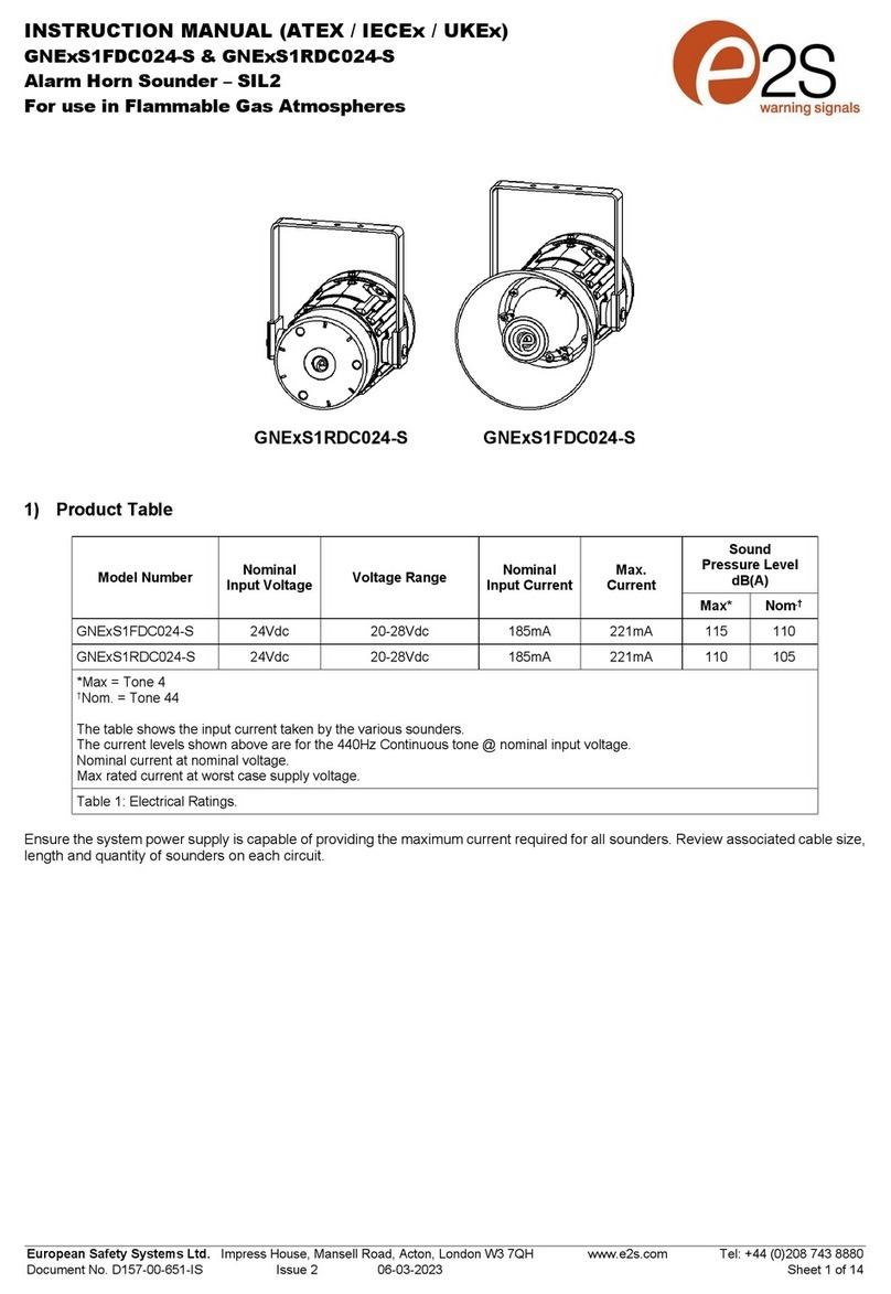
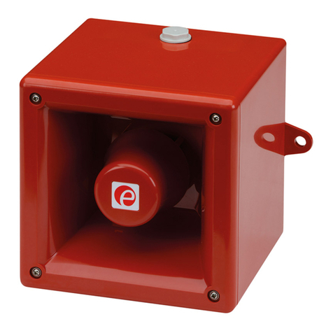
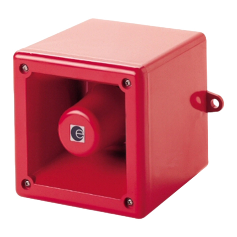
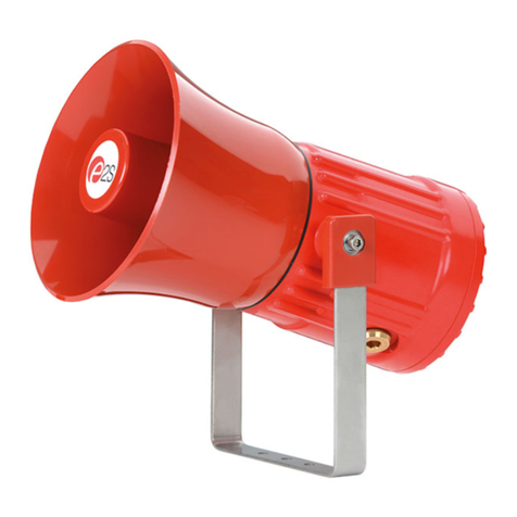
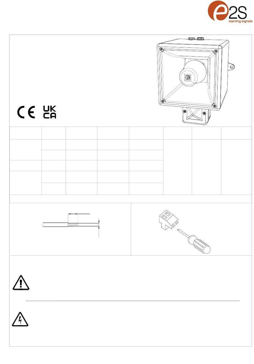
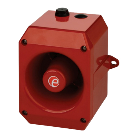
E2S MA1 Series User manual

   ----























 .† x‡ .† x‡ .† x‡




-



  
   
 
 
      
 
      


 



-


   
   
       
       
†‡x 
   
•
•--
•
•

- -






+
+
-
-
S2
S3
S2 S1

L/+
L/+
N/-
N/-
E
C
S2
S3
S2 S1

--
--
--

 




Вниманиеустановка должна выполняться электриком в соответствии с последними нормами и правилами

-




Вниманиеотключите от источника питания перед установкой или обслуживанием чтобы предотвратить поражение электрическим током
--














   ----


  1/2” 
  
 1/2”  1/2”


A
∠
B
C
A
∠
B
C








 


 




 


E2S Warning Signals Impress House, Mansell Road, Acton, London W3 7QH [email protected] e2s.com Page 1 of 1 D221-95-001-IS_Issue_C - 02/12/2022
1000Hz PFEER Toxic Gas
1200/500Hz @ 1Hz DIN /PFEER P.T.A.P.
1000Hz @ 0.5Hz(1s on, 1soff) PFEER Gen. Alarm
1.4KHz-1.6KHz 1s, 1.6KHz-1.4KHz 0.5s NF C 48-265
544Hz(100mS)/440Hz (400mS) NF S 32-001
1500/500Hz - (0.5s on , 0.5s off) x3 + 1s gap AS4428
500-1500Hz Sweeping 2 sec on 1 sec off AS4428
500/1200Hz @ 0.26Hz (3.3son, 0.5s off) Netherlands -
NEN 2575
1000Hz (1s on, 1s off)x7 + (7s on, 1s off) IMO Code 1a
420Hz(0.5s on, 0.5s off)x3 + 1s gap ISO 8201 Temporal
Pattern
1000Hz(0.5s on, 0.5s off)x3 + 1s gap ISO 8201 Temporal
Pattern
422/775Hz - (0.85 on, 0.5 off) x3 + 1s gap NFPA -
Temporal Coded
1000/2000Hz @ 1Hz Singapore
300Hz Continuous
440Hz Continuous
470Hz Continuous
500Hz Continuous IMO code 2 (Low)
554Hz Continuous
660Hz Continuous
800Hz IMO code 2 (High)
1200Hz Continuous
2000Hz Continuous
2400Hz Continuous
440Hz @0.83Hz (50
cycles/minute) Intermittent
470Hz @0.9Hz - 1.1s Intermittent
470Hz @5Hz - (5
cycles/second) Intermittent
544Hz @ 1.14Hz - 0.875s Intermittent
655Hz @ 0.875Hz Intermittent
660Hz @0.28Hz - 1.8sec
on, 1.8sec off Intermittent
660Hz @3.34Hz - 150mS
on, 150mS off Intermittent
745Hz @ 1Hz Intermittent
800Hz - 0.25sec on, 1 sec off Intermittent
800Hz @ 2Hz IMO code 3.a
(High) Intermittent
1000Hz @ 1Hz Intermittent
2400Hz @ 1Hz Intermittent
2900Hz @ 5Hz Intermittent
363/518Hz @ 1Hz Alternating
450/500Hz @ 2Hz Alternating
554/440Hz @ 1Hz Alternating
554/440Hz @ 0.625Hz Alternating
561/760Hz @0.83Hz (50
cycles/minute) Alternating
800/1000Hz @ 0.875Hz Alternating
2400/2900Hz @ 2Hz Alternating
500/1200Hz @ 0.3Hz Sweeping
560/1055Hz @ 0.18Hz Sweeping
560/1055Hz @ 3.3Hz Sweeping
660/1200Hz @ 1Hz Sweeping
800/1000Hz @ 1Hz Sweeping
800/1000Hz @ 7Hz Sweeping
800/1000Hz @ 50Hz Sweeping
2400/2900Hz @ 7Hz Sweeping
2400/2900Hz @ 1Hz Sweeping
2400/2900Hz @ 50Hz Sweeping
2500/3000Hz @ 2Hz Sweeping
2500/3000Hz @ 7.7Hz Sweeping
800Hz Motor Siren
1200Hz Motor Siren
2400Hz Motor Siren
Stage 1
Set DIP
SW 1
Tone No.
Tone Description Tone Visual
Stage 1 & 2
DIP SW 1/2
Settings
1 2 3 4 5 6
Stage 3
Set DIP
SW 1
(S3)
Stage 4
Set DIP
SW 1
(S2 + S3)
0 0 0 0 0 0
1
2
3
4
5
6
7
8
9
10
11
12
13
14
15
16
17
18
19
20
21
22
23
24
25
26
27
28
29
30
31
32
33
34
35
36
37
38
39
40
41
46
47
48
49
50
52
53
54
55
56
57
58
59
60
61
62
63
42
1 0 0 0 0 0
0 1 0 0 0 0
1 1 0 0 0 0
0 0 1 0 0 0
1 0 1 0 0 0
0 1 1 0 0 0
1 1 1 0 0 0
0 0 0 1 0 0
1 0 0 1 0 0
0 1 0 1 0 0
1 1 0 1 0 0
0 0 1 1 0 0
1 0 1 1 0 0
0 1 1 1 0 0
1 1 1 1 0 0
0 0 0 0 1 0
1 0 0 0 1 0
0 1 0 0 1 0
1 1 0 0 1 0
0 0 1 0 1 0
1 0 1 0 1 0
0 1 1 0 1 0
1 1 1 0 1 0
1 1 0 1 1 0
0 0 1 1 1 0
0 1 1 1 1 0
0 0 0 0 0 1
0 1 0 0 0 1
1 1 0 0 0 1
0 0 1 0 0 1
1 0 1 0 0 1
0 1 1 0 0 1
1 1 1 0 0 1
0 0 0 1 0 1
0 1 0 1 0 1
1 0 1 1 0 1
0 1 1 1 0 1
1 1 1 1 0 1
0 0 0 0 1 1
1 0 0 0 1 1
0 1 0 0 1 1
1 1 0 0 1 1
0 0 1 0 1 1
1 0 1 0 1 1
0 1 1 0 1 1
1 1 1 0 1 1
0 0 0 1 1 1
1 0 0 1 1 1
0 1 0 1 1 1
1 1 0 1 1 1
0 0 1 1 1 1
1 0 1 1 1 1
0 1 1 1 1 1
0 0 0 1 1 0
1 0 0 1 1 0
0 1 0 1 1 0
1 1 1 1 1 0
1 0 0 0 0 1
1 0 0 1 0 1
1 0 1 1 1 0
1000Hz
1200Hz
500Hz 1s
1000Hz 1s
1s
1600Hz
1400Hz 1s
0.5s
544Hz 0.1s
0.4s
440Hz
0.5s
1500Hz
500Hz 0.5s 0.5s 0.5s 0.5s 1s
2s 1s
3s 0.5s
1500Hz
500Hz
1200Hz
500Hz
1000Hz
1s
1s
1s
1s
1s
1s
1s
1s
1s
1s
1s
1s
1s
1s
7s
7s
420Hz 0.5s
0.5s
0.5s
0.5s
0.5s
1s
1000Hz 0.5s
0.5s
0.5s
0.5s
0.5s
1s
775Hz
422Hz 0.85 0.5s 0.85 0.5s 0.85
2000Hz
1000Hz
f(Hz)
a(s)
b(s)
(f=440, a=0.6, b=0.6)
(f=470, a=0.55, b=0.55)
(f=470, a=0.1, b=0.1)
(f=470, a=0.43, b=0.44)
(f=655, a=0.57, b=0.57)
(f=660, a=1.8, b=1.8)
(f=660, a=0.15, b=0.15)
(f=745, a=0.5, b=0.5)
(f=800, a=0.25, b=1)
(f=800, a=0.25, b=0.25)
(f=1000, a=0.5, b=0.5)
(f=2400, a=0.5, b=0.5)
(f=2900, a=0.1, b=0.1)
f1(Hz)
a(s)
f(Hz)
f1(Hz)
a(s) a(s)
f(Hz)
(f=363, f1=518, a=0.1)
(f=450, f1=500, a=0.25)
(f=440, f1=554, a=0.5)
(f=440, f1=554, a=0.8)
(f=561, f1=760, a=0.6)
0 0 1 1 0 1
1 1 0 1 0 1
43
44
45
780/600Hz @ 0.96Hz Alternating
800/1000Hz @ 2Hz Alternating
970/800Hz @ 2Hz Alternating
64 Simulated Bell 1 1 1 1 1 1
f1(Hz)
a(s) a(s)
f(Hz)
(f=800, f1=1000, a=0.57)
(f=2400, f1=2900, a=0.25)
f1(Hz)
a(s) a(s)
f(Hz)
(f=800, f1=1000, a=0.25)
f1(Hz) a(s) a(s)
f(Hz)
(f=600, f1=780, a=0.52)
f1(Hz) a(s) a(s)
f(Hz)
(f=800, f1=970, a=0.25)
(f=500, f1=1200, a=3.34)
(f=560, f1=1055, a=5.47)
(f=560, f1=1055, a=0.3)
f1(Hz)
a(s)
f(Hz)
51 600/1250Hz @ 0.125Hz Sweeping (f=600, f1=1250, a=8)
f(Hz)
a(s)
(f=800, a=1.6)
(f=1200, a=2)
(f=2400, a=1.7)
1450Hz 0.25s
0.69ms
(f=660, f1=1200, a=1)
(f=800, f1=1000, a=1)
(f=800, f1=1000, a=0.14)
(f=800, f1=1000, a=0.02)
(f=2400, f1=2900, a=0.14)
(f=2400, f1=2900, a=1)
(f=2400, f1=2900, a=0.02)
(f=2500, f1=3000, a=0.5)
(f=2500, f1=3000, a=0.13)
(f=300)
(f=440)
(f=470)
(f=500)
(f=554)
(f=660)
(f=800)
(f=1200)
(f=2000)
(f=2400)
f(Hz)
0.5s
2
3
2
24
19
44
44
24
34
34
1
1
1
3
44
44
44
24
24
24
24
24
24
24
24
24
24
8
8
24
8
24
24
24
24
24
24
24
24
24
24
24
24
24
24
24
24
24
8
8
24
8
21
24
24
24
24
24
24
24
24
24
3
20
44
44
44
1
1
1
1
35
1
1
8
8
8
35
8
8
8
8
8
8
8
8
8
19
19
19
19
19
19
19
19
19
19
19
19
19
19
12
12
12
12
12
12
12
12
12
12
12
12
12
12
12
12
1
1
8
8
8
35
35
35
35
35
f1(Hz)
a(s)
f(Hz)
0.5s 0.5s
1s
warning signals
2S
M RANGE
EUROPEAN SAFETY SYSTEMS LTD
IMPRESS HOUSE
MANSELL ROAD
ACTON
LONDON W3 7QH
WWW.E2S.COM
C
THIS DRAWING AND ANY INFORMATION OR DESCRIPTIVE
MATTER THEREIN IS COMMUNICATED IN CONFIDENCE AND
IS THE COPYRIGHT PROPERTY OF EUROPEAN SAFETY
SYSTEMS LTD. NEITHER THE WHOLE OR ANY EXTRACT MAY
BE DISCLOSED, LOANED, COPIED OR USED FOR
MANUFACTURING OR TENDERING PURPOSES WITHOUT THEIR
WRITTEN CONSENT.
EUROPEAN SAFETY SYSTEMS LTD.
AS PER LATEST DATE OF ISSUE SHOWN ABOVE
DRAWING TO BS8888:2000
GEOMETRIC TOLERANCES TO ISO1101:1983
LINEAR DIMENSIONAL TOLS
ANGULAR DIMENSIONAL TOLS
STANDARDS
MOD No. REASON - INITIAL - DATEISSUE
DATE
APPROVED
CHECKED DATE
DATE
DRAWN WEIGHT (Kg)
SURFACE FINISH
MATERIAL
ALTERNATIVE MATERIAL SHEETSCALE
TITLE
A3
IF IN DOUBT, ASK -
DO NOT SCALE
ALL DIMENSIONS IN MM
DRAWING NUMBER
A
B
C
D
E
F
G
109
G
F
E
78
6
5
D
C
134
2
A
B
D207-06-001
R.S.RAIT
B.ISARD
R.N.POTTS OF
MA1R, MA1F, MA2F & MA2H DC
SOUNDER WIRING DIAGRAMS
INTRODUCTION
NTS 1 3
OPTIONAL LINE MONITORING RESISTOR, CUSTOMER SUPPLIED,
14V MAX SYSTEM = 120Ω MIN, 2W MIN OR 1KΩ MIN, 0.5W MIN
28V MAX SYSTEM = 470Ω MIN, 2W MIN OR 2.4KΩ MIN, 0.5W MIN
RECOMMENDED MINIMUM VALUES:
R1
Stage 1 +ve IN
Stage 1 +ve OUT
Common -ve IN
Common -ve OUT
Stage 2 +ve
Stage 1 +ve IN
Stage 1 +ve OUT
Common -ve IN
Common -ve OUT
Stage 2 +ve
Stage 3 +ve
R1
+
-
-
+
R1
+
-
-
+
S2
R1
+
-
-
+
S2
S3
Stage 1 +ve IN
Stage 1 +ve OUT
Stage 1 -ve IN
Stage 1 -ve OUT
Single Stage Configuration Config.: 1a
Line Monitoring
Set to positive switching (default)
Stage 1: Apply Power to Stage 1 +ve & Stage 1 -ve
Two Stage Configuration Config.: 1b
Common Negative
Set to positive switching (default)
Stage 1: Apply Power to Stage 1 +ve & Common -ve
Stage 2: Apply Power to Stage 2 +ve & Common -ve
Three/Four Stage Configuration Config.: 1c
Common Negative
Set to positive switching (default)
Stage 1: Apply Power to Stage 1 +ve & Common -ve
Stage 2: Apply Power to Stage 2 +ve &Common -ve
Stage 3: Apply Power to Stage 3 +ve &Common -ve
Stage 4: Apply Power to Stage 2 +ve, Stage 3 +ve & Common -ve
05/03/2021
RSR - 05/03/2021
A
05/03/2021
05/03/2021
Configuration titles amended
RSR - 19/05/2021
B
Product Versions Updated
RSR - 29/03/2023
CACN0129
warning signals
2S
M RANGE
EUROPEAN SAFETY SYSTEMS LTD
IMPRESS HOUSE
MANSELL ROAD
ACTON
LONDON W3 7QH
WWW.E2S.COM
C
THIS DRAWING AND ANY INFORMATION OR DESCRIPTIVE
MATTER THEREIN IS COMMUNICATED IN CONFIDENCE AND
IS THE COPYRIGHT PROPERTY OF EUROPEAN SAFETY
SYSTEMS LTD. NEITHER THE WHOLE OR ANY EXTRACT MAY
BE DISCLOSED, LOANED, COPIED OR USED FOR
MANUFACTURING OR TENDERING PURPOSES WITHOUT THEIR
WRITTEN CONSENT.
EUROPEAN SAFETY SYSTEMS LTD.
AS PER LATEST DATE OF ISSUE SHOWN ABOVE
DRAWING TO BS8888:2000
GEOMETRIC TOLERANCES TO ISO1101:1983
LINEAR DIMENSIONAL TOLS
ANGULAR DIMENSIONAL TOLS
STANDARDS
MOD No. REASON - INITIAL - DATEISSUE
DATE
APPROVED
CHECKED DATE
DATE
DRAWN WEIGHT (Kg)
SURFACE FINISH
MATERIAL
ALTERNATIVE MATERIAL SHEETSCALE
TITLE
A3
IF IN DOUBT, ASK -
DO NOT SCALE
ALL DIMENSIONS IN MM
DRAWING NUMBER
A
B
C
D
E
F
G
109
G
F
E
78
6
5
D
C
134
2
A
B
D207-06-001
R.S.RAIT
B.ISARD
R.N.POTTS
MA1R, MA1F, MA2F & MA2H DC
SOUNDER WIRING DIAGRAMS
NTS
SWITCHES FOR STAGE OPERATION
CUSTOMER SUPPLIED
H2
H1
Stage 1 +ve
Stage 1 -ve
Stage 2 -ve
Stage 2 +ve
OF
2 3
R1
+
-
-
+
S2
S3
R1
+
-
-
+
S2
R2
OPTIONAL LINE MONITORING RESISTOR, CUSTOMER SUPPLIED,
14V MAX SYSTEM = 120Ω MIN, 2W MIN OR 1KΩ MIN, 0.5W MIN
28V MAX SYSTEM = 470Ω MIN, 2W MIN OR 2.4KΩ MIN, 0.5W MIN
RECOMMENDED MINIMUM VALUES:
R1
Set H1 & H2 to -ve switching
Three/Four Stages. Voltage Free 2nd, 3rd & 4th Stage Activation Configuration Config.: 2
Common Positive
Customer Set H1 & H2 to Negative Switching (See Below)
Stage 1: Apply Power to Common +ve & Stage 1 -ve
Stage 2: Apply Power to Common +ve & Stage 1 -ve & connect Stage 2 -ve to Stage 1 -ve
Stage 3: Apply Power to Common +ve & Stage 1 -ve & connect Stage 3 -ve to Stage 1 -ve
Stage 4: Apply Power to Common +ve & Stage 1 -ve
& connect Stage 2 -ve & Stage 3 -ve to Stage 1 -ve
Two Stage Configuration Config.: 3
Independent Stage Input
Reverse Polarity Stage Monitoring
Stage 1: Apply Power to Stage 1 +ve & Stage 1 -ve
Stage 2: Apply Power to Stage 1 +ve & Stage 1 -ve & connect Stage 2 -ve to Stage 1 -ve
H2
H1
Set H1 & H2 to -ve switching
Cut Link W1
05/03/2021
INTRODUCTION
RSR - 05/03/2021
A
05/03/2021
05/03/2021
Stage 2 -ve
Common +ve IN
Common +ve OUT
Stage 1 -ve OUT
Stage 3 -ve
Stage 1 -ve IN
RSR - 19/05/2021
BConfiguration titles amended
Product Versions Updated
RSR - 29/03/2023
CACN0129
Stage 1 -ve
+ve IN
+ve OUT
-ve OUT
Stage 2 -ve
-ve IN/COMMON
warning signals
2S
M RANGE
EUROPEAN SAFETY SYSTEMS LTD
IMPRESS HOUSE
MANSELL ROAD
ACTON
LONDON W3 7QH
WWW.E2S.COM
C
THIS DRAWING AND ANY INFORMATION OR DESCRIPTIVE
MATTER THEREIN IS COMMUNICATED IN CONFIDENCE AND
IS THE COPYRIGHT PROPERTY OF EUROPEAN SAFETY
SYSTEMS LTD. NEITHER THE WHOLE OR ANY EXTRACT MAY
BE DISCLOSED, LOANED, COPIED OR USED FOR
MANUFACTURING OR TENDERING PURPOSES WITHOUT THEIR
WRITTEN CONSENT.
EUROPEAN SAFETY SYSTEMS LTD.
AS PER LATEST DATE OF ISSUE SHOWN ABOVE
DRAWING TO BS8888:2000
GEOMETRIC TOLERANCES TO ISO1101:1983
LINEAR DIMENSIONAL TOLS
ANGULAR DIMENSIONAL TOLS
STANDARDS
MOD No. REASON - INITIAL - DATEISSUE
DATE
APPROVED
CHECKED DATE
DATE
DRAWN WEIGHT (Kg)
SURFACE FINISH
MATERIAL
ALTERNATIVE MATERIAL SHEETSCALE
TITLE
A3
IF IN DOUBT, ASK -
DO NOT SCALE
ALL DIMENSIONS IN MM
DRAWING NUMBER
A
B
C
D
E
F
G
109
G
F
E
78
6
5
D
C
134
2
A
B
D207-06-001
R.S.RAIT
B.ISARD
R.N.POTTS
MA1R, MA1F, MA2F & MA2H DC
SOUNDER WIRING DIAGRAMS
NTS
Stage 1 +ve
Stage 1 -ve
Stage 1 +ve IN
Stage 1 +ve OUT
Stage 2 +ve
Stage 2 -ve
Stage 1 -ve OUT
Stage 1 -ve IN
Stage 2 +ve IN
Stage 2 +ve OUT
Stage 2 -ve OUT
Stage 2 -ve IN
Stage 3 +ve IN
Stage 3 +ve OUT
Stage 3 -ve OUT
Stage 3 +ve IN
OF
3 3
R1
+
-
-
+
R1
+
-
-
+
S2
R2
R1R2R3
Two Stage Configuration Config.: 4
Line Stage Monitoring (Use suitable monitoring relays/modules)
Not to be used for reverse polarity monitoring
Stage 1: Apply Power to Stage 1 +ve & Stage 1 -ve
Stage 2: Apply Power to Stage 2 +ve & Stage 2 -ve
Two/Three Stage Voltage Free Activation Configuration Config.: 5
Customer Set H1 & H2 to Negative Switching (See Below)
Power: +ve & -ve
Stage 1: Connect Stage 1 -ve to Common -ve
Stage 2: Cconnect Stage 2 -ve to Common -ve
Stage 3: Connect both Stage 1 -ve & Stage 2 -ve to Common -ve
Three/Four Stage Configuration Config.: 6
Independent Stage Input
Line Stage Monitoring (Use suitable monitoring relays/modules)
Set to positive switching (Default)
Stage 1: Apply Power to Stage 1 +ve & Stage 1 -ve
Stage 2: Apply Power to Stage 2 +ve & Stage 2 -ve
Stage 3: Apply Power to Stage 3 +ve & Stage 3 -ve
Stage 4: Apply Power to Stage 2 +ve & Stage 2 -ve
& apply Power to Stage 3 +ve & Stage 3 -ve
CUSTOM
CONFIGURATION
PRODUCT
OPTION 'Y'
Cut Link W1
H2
H1
Set H1 & H2 to -ve switching
CUSTOM
CONFIGURATION
PRODUCT
OPTION 'K'
CUSTOM
CONFIGURATION
PRODUCT
OPTION 'V'
SWITCHES FOR STAGE OPERATION
CUSTOMER SUPPLIED
OPTIONAL LINE MONITORING RESISTOR, CUSTOMER SUPPLIED,
14V MAX SYSTEM = 120Ω MIN, 2W MIN OR 1KΩ MIN, 0.5W MIN
28V MAX SYSTEM = 470Ω MIN, 2W MIN OR 2.4KΩ MIN, 0.5W MIN
RECOMMENDED MINIMUM VALUES:
R1
05/03/2021
INTRODUCTION
RSR - 05/03/2021
A
05/03/2021
05/03/2021
RSR - 19/05/2021
BConfiguration titles amended
S1
S2
Product Versions Updated
RSR - 29/03/2023
CACN0129
warning signals
2S
M RANGE
EUROPEAN SAFETY SYSTEMS LTD
IMPRESS HOUSE
MANSELL ROAD
ACTON
LONDON W3 7QH
WWW.E2S.COM
C
THIS DRAWING AND ANY INFORMATION OR DESCRIPTIVE
MATTER THEREIN IS COMMUNICATED IN CONFIDENCE AND
IS THE COPYRIGHT PROPERTY OF EUROPEAN SAFETY
SYSTEMS LTD. NEITHER THE WHOLE OR ANY EXTRACT MAY
BE DISCLOSED, LOANED, COPIED OR USED FOR
MANUFACTURING OR TENDERING PURPOSES WITHOUT THEIR
WRITTEN CONSENT.
EUROPEAN SAFETY SYSTEMS LTD.
AS PER LATEST DATE OF ISSUE SHOWN ABOVE
DRAWING TO BS8888:2000
GEOMETRIC TOLERANCES TO ISO1101:1983
LINEAR DIMENSIONAL TOLS
ANGULAR DIMENSIONAL TOLS
STANDARDS
MOD No. REASON - INITIAL - DATEISSUE
DATE
APPROVED
CHECKED DATE
DATE
DRAWN WEIGHT (Kg)
SURFACE FINISH
MATERIAL
ALTERNATIVE MATERIAL SHEETSCALE
TITLE
A3
IF IN DOUBT, ASK -
DO NOT SCALE
ALL DIMENSIONS IN MM
DRAWING NUMBER
A
B
C
D
E
F
G
109
G
F
E
78
6
5
D
C
134
2
A
B
D207-06-005
R.S.RAIT
B.ISARD
R.N.POTTS OF
MA1R, MA1F, MA2F, MA2H AC
SOUNDER WIRING DIAGRAMS
INTRODUCTION
NTS 1
SWITCHES FOR STAGE OPERATION
CUSTOMER SUPPLIED
1
Earth Earth
Stage 2
Stage 3
Common
Live IN
Live OUT
Neutral IN
Neutral OUT
Earth
Stage 1
Stage 2
Common
N
N
L
L
E
N
N
L
L
E
C
N
N
L
L
E
C
S2
S3
Live IN
Live OUT
Neutral IN
Neutral OUT
Stage 1 Live IN
Stage 1 Live OUT
Stage 1 Neutral IN
Stage 1 Neutral OUT
Single Stage Configuration Config.: 1a
Stage 1: Apply Power to Stage 1 Live & Stage 1 Neutral
Two Stage Voltage Free Activation Configuration Config.: 2
Power: Live & Neutral
Stage 1: Connect Stage 1 to Common
Stage 2: Connect Stage 2 to Common
Stage 3: Connect both Stage 1 & Stage 2 to Common
Three/Four Stage Configuration Config.: 1b
Stage 1: Apply Power to Live & Neutral
Stage 2: Apply Power to Live & Neutral
& connect Stage 2 to Common
Stage 3: Apply Power to Live & Neutral
& connect Stage 3 to Common
Stage 4: Apply Power to Live & Neutral
& connect both Stage 2 & Stage 3 to Common
05/03/2021
INTRODUCTION
RSR - 05/03/2021
A
05/03/2021
05/03/2021
CUSTOM
CONFIGURATION
PRODUCT
OPTION 'K'
S1
S2
PRODUCT OPTION K CLARIFIED
RSR - 29/03/2023
BACN0129

This manual suits for next models

13

Other E2S Marine Equipment manuals

E2S STExC1 User manual

E2S

E2S STExC1 User manual

E2S A112N User manual

E2S

E2S A112N User manual

E2S GNExS1 User manual

E2S

E2S GNExS1 User manual

E2S D2xB1LD2 User manual

E2S

E2S D2xB1LD2 User manual

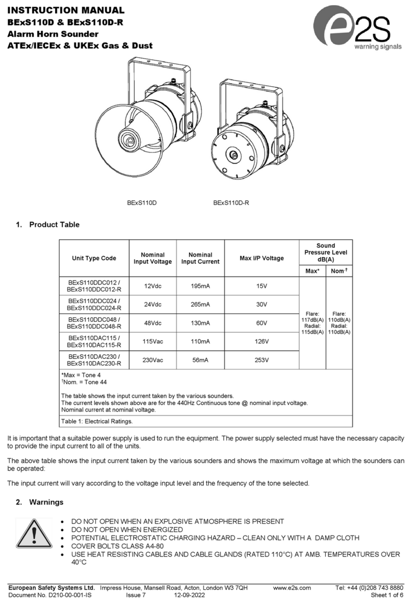
E2S BExS110D User manual

E2S

E2S BExS110D User manual

E2S A100SONTEL User manual

E2S

E2S A100SONTEL User manual

E2S BExCS110-05D-P User manual

E2S

E2S BExCS110-05D-P User manual

E2S STExS1 User manual

E2S

E2S STExS1 User manual

E2S IS-AL105NL User manual

E2S

E2S IS-AL105NL User manual

E2S BE DCS110-05D Series User manual

E2S

E2S BE DCS110-05D Series User manual

E2S A105N APPELLO DC User manual

E2S

E2S A105N APPELLO DC User manual

E2S IS-mA1M User manual

E2S

E2S IS-mA1M User manual

E2S GNExS2 User manual

E2S

E2S GNExS2 User manual

E2S AlertAlarm A105N User manual

E2S

E2S AlertAlarm A105N User manual

E2S BExCTS110-05D-P User manual

E2S

E2S BExCTS110-05D-P User manual

E2S IS-A105N User manual

E2S

E2S IS-A105N User manual

E2S BExDCTS110-05D User manual

E2S

E2S BExDCTS110-05D User manual

E2S BExS110D-SIL User manual

E2S

E2S BExS110D-SIL User manual

E2S D1xS2FDC024-A User manual

E2S

E2S D1xS2FDC024-A User manual

E2S BE DCS110-L1D Series User manual

E2S

E2S BE DCS110-L1D Series User manual

E2S D1xS1RDC024-S User manual

E2S

E2S D1xS1RDC024-S User manual

E2S E2xS1RDC024 Manual

E2S

E2S E2xS1RDC024 Manual

E2S E2xS2FDC024 User manual

E2S

E2S E2xS2FDC024 User manual

E2S IS-D105 User manual

E2S

E2S IS-D105 User manual

Popular Marine Equipment manuals by other brands

Seastar Solutions Optimus Seastation Quick reference guide

Seastar Solutions

Seastar Solutions Optimus Seastation Quick reference guide

New Age PRM 301 Workshop manual

New Age

New Age PRM 301 Workshop manual

Raymarine SeaNet-Alarm Installation and operation manual

Raymarine

Raymarine SeaNet-Alarm Installation and operation manual

Kongsberg EM 2000 Maintenance manual

Kongsberg

Kongsberg EM 2000 Maintenance manual

Garmin GNX Installation instruction

Garmin

Garmin GNX Installation instruction

Nexus Wind Data Installation and operation manual

Nexus

Nexus Wind Data Installation and operation manual

Scanstrut Aluminium PowerTower APT-150-01 installation instructions

Scanstrut

Scanstrut Aluminium PowerTower APT-150-01 installation instructions

Ziton ZP755WV-2R Installation sheet

Ziton

Ziton ZP755WV-2R Installation sheet

Rwo DEB 0.1 Installation, operating and maintenance manual

Rwo

Rwo DEB 0.1 Installation, operating and maintenance manual

Eaton DB3B Technical manual

Eaton

Eaton DB3B Technical manual

DIGITAL YACHT ENGINELINK NMEA 2000 ENGINE MONITOR Installation and instruction manual

DIGITAL YACHT

DIGITAL YACHT ENGINELINK NMEA 2000 ENGINE MONITOR Installation and instruction manual

Garmin GPSMAP 527  Guide Reference

Garmin

Garmin GPSMAP 527 Guide Reference

Boss Audio Systems MR1308UAB user manual

Boss Audio Systems

Boss Audio Systems MR1308UAB user manual

Rockford Fosgate RFX3000 Operation manual

Rockford Fosgate

Rockford Fosgate RFX3000 Operation manual

Yacht Sentinel Sentinel Domotics quick start guide

Yacht Sentinel

Yacht Sentinel Sentinel Domotics quick start guide

UniPOS 8204C instruction manual

UniPOS

UniPOS 8204C instruction manual

Roswell Area 53 Bimini Series Installation & Usage Instructions

Roswell

Roswell Area 53 Bimini Series Installation & Usage Instructions

MEDC HORN DB3 Technical manual

MEDC

MEDC HORN DB3 Technical manual

manuals.online logo
manuals.online logoBrands
  • About & Mission
  • Contact us
  • Privacy Policy
  • Terms and Conditions

Copyright 2025 Manuals.Online. All Rights Reserved.