E2S D1xC1 Series User manual

INSTRUCTION MANUAL
D1xC1 & D1xC2
Alarm Horn Sounder & Strobe
Class I, Zone 1, 2, 21 & 22
European Safety Systems Ltd. Impress House, Mansell Road, Acton, London W3 7QH www.e2s.com Tel: +44 (0)208 743 8880
Document No. D190-00-301-IS Issue 2 17-03-2022 Sheet 1 of 9
D1xC1-R & D1xC2-R D1xC1-F D1xC2-F
1) Product Table
Unit Type Code Nominal
Input Voltage
Nominal
Input Current Voltage Range
Sound
Pressure Level dB(A)
Max* Nom.†
D1xC1X05RDC024-
A
24Vdc 508m
A
20-28Vdc
110 105
D1xC1X05RAC115-
A
115Vac 200m
A
110-120Vac 50/60Hz
D1xC1X05RAC230-
A
230Vac 127m
A
220-240Vac 50/60Hz
D1xC1X10RDC024-
A
24Vdc 858m
A
20-28Vdc
D1xC1X10RAC115-
A
115Vac 317m
A
110-120Vac 50/60Hz
D1xC1X10RAC230-
A
230Vac 169m
A
220-240Vac 50/60Hz
D1xC1X05FDC024-
A
24Vdc 508m
A
20-28Vdc
115 110
D1xC1X05FAC115-
A
115Vac 200m
A
110-120Vac 50/60Hz
D1xC1X05FAC230-
A
230Vac 127m
A
220-240Vac 50/60Hz
D1xC1X10FDC024-
A
24Vdc 858m
A
20-28Vdc
D1xC1X10FAC115-
A
115Vac 317m
A
110-120Vac 50/60Hz
D1xC1X10FAC230-
A
230Vac 169m
A
220-240Vac 50/60Hz
D1XC2X05RDC024-
A
24Vdc P2/P3: 647/1063m
A
20-28Vdc
P2/P3
112/114
P2/P3
107/109
D1xC2X05RAC115-
A
115Vac P2/P3: 255/415m
A
110-120Vac 50/60Hz
D1xC2X05RAC230-
A
230Vac P2/P3: 157/246m
A
220-240Vac 50/60Hz
D1XC2X05DC024-
A
24Vdc P2/P3: 647/1063m
A
20-28Vdc
P2/P3
120/123
P2/P3
115/118
D1xC2X05FAC115-
A
115Vac P2/P3: 255/415m
A
110-120Vac 50/60Hz
D1xC2X05FAC230-
A
230Vac P2/P3: 157/246m
A
220-240Vac 50/60Hz
D1xC2X10RDC024-
A
24Vdc P2/P3: 997/1413m
A
20-28Vdc
P2/P3
112/114 P2/P3
107/109
D1xC2X10RAC115-
A
115Vac P2/P3: 372/532m
A
110-120Vac 50/60Hz
D1xC2X10RAC230-
A
230Vac P2/P3: 199/288m
A
220-240Vac 50/60Hz
D1xC2X10FDC024-
A
24Vdc P2/P3: 997/1413m
A
20-28Vdc
P2/P3
120/123 P2/P3
115/118
D1xC2X10FAC115-
A
115Vac P2/P3: 372/532m
A
110-120Vac 50/60Hz
D1xC2X10FAC230-
A
230Vac P2/P3: 199/288m
A
220-240Vac 50/60Hz
*Max = Tone 4†Nom. = Tone 44
The table shows the input current taken by the various sounders.
The current levels shown above are for the 440Hz Continuous tone @ nominal input voltage.
Nominal current at nominal voltage.
Table 1: Electrical Ratings.

European Safety Systems Ltd. Impress House, Mansell Road, Acton, London W3 7QH www.e2s.com Tel: +44 (0)208 743 8880
Document No. D190-00-301-IS Issue 2 17-03-2022 Sheet 2 of 9
2) Warnings
CAUTION
TO REDUCE THE RISK OF IGNITION OF HAZARDOUS
ATMOSPHERES:
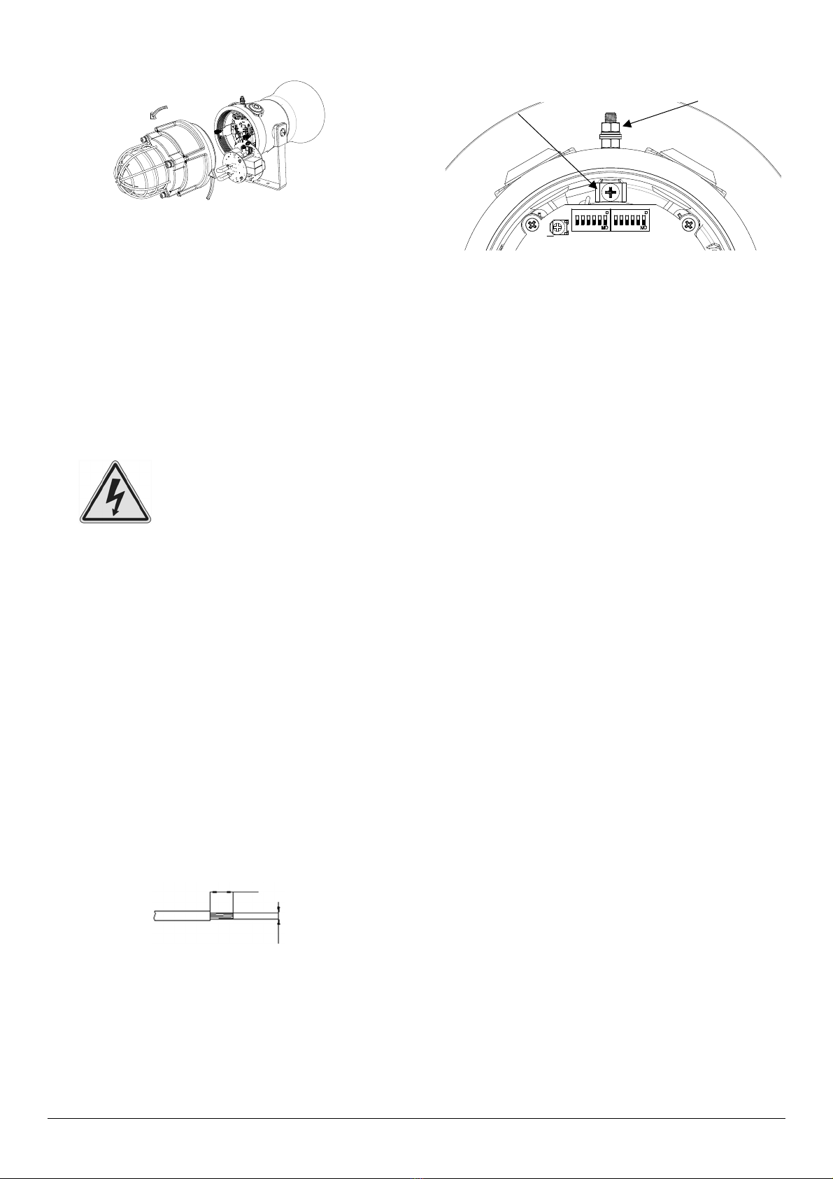
DISCONNECT FROM SUPPLY BEFORE OPENING.
KEEP TIGHTLY CLOSED WHEN IN OPERATION.
WARNING
FIT SEALING FITTING IN CONDUIT RUNS WITHIN 18 INCHES
FROM ENCLOSURE.
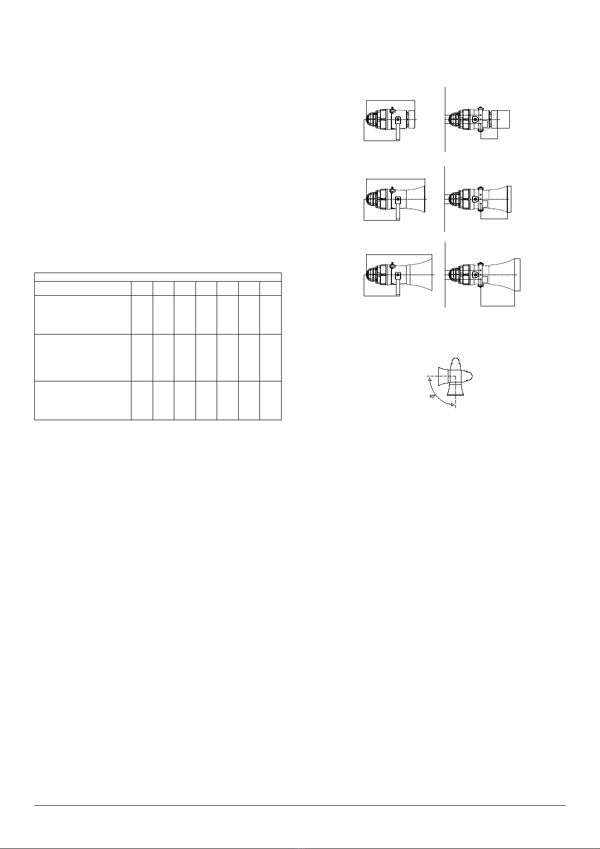
EQUIPMENT MUST NOT BE INSTALLED WITH THE HORN FACING
UPWARDS OF HORIZONTAL
DO NOT OPEN WHEN AN EXPLOSIVE ATMOSPHERE IS
PRESENT
DO NOT OPEN WHEN ENERGISED
POTENTIAL ELECTROSTATIC CHARGING HAZARD - CLEAN
ONLY WITH A DAMP CLOTH
ENCLOSURE ENTRIES: TWIN M20 X 1.5 / SINGLE 1/2” NPT
ATEX/IECEx & UKEx INSTALLATIONS: IF TEMPERATURE
EXCEEDS 70°C AT ENTRY OR 80°C AT BRANCHING POINT USE
SUITABLE RATED CABLE AND GLANDS
ATTENTION
POUR REDUIRE LE RISQUE D’INFLAMMATION DES
ATMOSPHÈRES DANGEREUSES :
COUPER L 'ALIMENTATION AVANT OUVERTURE.
CONSERVER FERMÉ PENDANT LE FONCIONNEMENT.
AVERTISSEMENT
CONDUITS DOIVENT ETRE SCELLES EN MOINS DE 18 POUCES.
ÉQUIPEMENT NE DOIT PAS ETRE INSTALLE AVEC LE KLAXON
TOURNEE VERS LE HAUT DE HORIZONTAL.
NE PAS OUVRIR UN PRESENCE D’ATMOSPHERE EXPLOSIVE
NE PAS OUVRIR ENERGIE
DANGER POTENTIEL CHARGE ÉLECTROSTATIQUE - NETTOYER
UNIQUEMENT AVEC UN CHIFFON HUMIDE
ENTRÉES DE BOÎTIER: 2 x M20 X 1.5 / 1 x 1/2” NPT
ATEX/IECEx & UKEx INSTALLATIONS : SI LA TEMPÉRATURE
DÉPASSE 70 °C À L'ENTRÉE OU 80 °C AU POINT DE
BRANCHEMENT, UTILISER UN CÂBLE ET DES JOINTS
D'ÉTANCHÉITÉ APPROPRIÉS
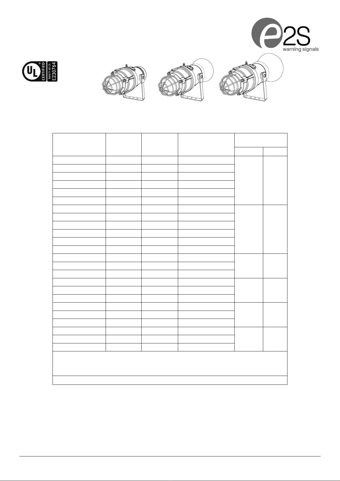
3) Marking & Rating Information
The D1xS1 Alarm Horns comply with the following standards for
hazardous locations:
3.1 Class/Division Ratings for US & Canada
Standards
Class I UL 1203 & CSA C22.2 No 30-M1986
Class Division Ratings for US (NEC)
Model No: Rating
D1xC1X05-DC024-A/
D1xC2X05-DC024-A
Class I Div 1 ABCD T4 Ta -55°C to +85°C
Class I Div 1 ABCD T4A Ta -55°C to +80°C
Class I Div 1 ABCD T5 Ta -55°C to +60°C
Class I Div 1 ABCD T6 Ta -55°C to +45°C
D1xC1X05-AC115-A/
D1xC2X05-AC115-A/
D1xC1X05-AC230-A/
D1xC2X05-AC230-A/
Class I Div 1 ABCD T4 Ta -55°C to +85°C
Class I Div 1 ABCD T4A Ta -55°C to +70°C
Class I Div 1 ABCD T5 Ta -55°C to +50°C
D1xC1X10-DC024-A/
D1xC2X10-DC024-A
Class I Div 1 ABCD T3C Ta -55°C to +85°C
Class I Div 1 ABCD T4 Ta -55°C to +70°C
Class I Div 1 ABCD T4A Ta -55°C to +55°C
D1xC1X10-AC115-A/
D1xC2X10-AC115-A/
D1xC1X10-AC230-A/
D1xC2X10-AC230-A/
Class I Div 1 ABCD T3C Ta -55°C to +85°C
Class I Div 1 ABCD T4 Ta -55°C to +65°C
Class I Div 1 ABCD T4A Ta -55°C to +50°C
Class Division Ratings for Canada (CEC)
Model No: Rating
D1xC1X05-DC024-A/
D1xC2X05-DC024-A
Class I Div 1 ABCD T5 Ta -55°C to +55°C
Class I Div 1 ABCD T6 Ta -55°C to +45°C
D1xC1X10-DC024-A/
D1xC2X10-DC024-A
Class I Div 1 ABCD T4A Ta -55°C to +55°C
Class Zone Ratings for US (NEC)
Model No: Rating
D1xC1X05-DC024-A/
D1xC2X05-DC024-A
Class I Zone 1 IIC T4 Ta -55°C to +85°C
Class I Zone 1 IIC T4A Ta -55°C to +80°C
Class I Zone 1 IIC T5 Ta -55°C to +60°C
Class I Zone 1 IIC T6 Ta -55°C to +45°C
D1xC1X05-AC115-A/
D1xC2X05-AC115-A/
D1xC1X05-AC230-A/
D1xC2X05-AC230-A/
Class I Zone 1 IIC T4 Ta -55°C to +85°C
Class I Zone 1 IIC T4A Ta -55°C to +70°C
Class I Zone 1 IIC T5 Ta -55°C to +50°C
D1xC1X10-DC024-A/
D1xC2X10-DC024-A
Class I Zone 1 IIC T3C Ta -55°C to +85°C
Class I Zone 1 IIC T4 Ta -55°C to +70°C
Class I Zone 1 IIC T4A Ta -55°C to +55°C
D1xC1X10-AC115-A/
D1xC2X10-AC115-A/
D1xC1X10-AC230-A/
D1xC2X10-AC230-A/
Class I Zone 1 IIC T3C Ta -55°C to +85°C
Class I Zone 1 IIC T4 Ta -55°C to +65°C
Class I Zone 1 IIC T4A Ta -55°C to +50°C
Class Zone Ratings for Canada (CEC)
Model No: Rating
D1xC1X05-DC024-A/
D1xC2X05-DC024-A
Class I Zone 1 IIC T5 Ta -55°C to +55°C
Class I Zone 1 IIC T6 Ta -55°C to +45°C
D1xC1X10-DC024-A/
D1xC2X10-DC024-A
Class I Zone 1 IIC T4A Ta -55°C to +55°C
Installation must be carried out in compliance with the National
Electric Code / Canadian Electric Code
3.2 ATEX / IECEx & UKEx Ratings
Standards
EN60079-0:2018/IEC60079-0:2017 (ed.7): Explosive Atmospheres -
Equipment General Requirements.
EN60079-1:2014/IEC60079-1:2014 (ed.7): Explosive Atmospheres -
Equipment Protection by Flameproof Enclosures “d”.
EN60079-31:2014/IEC60079-31:2013 (ed.2): Explosive Atmospheres -
Equipment Dust Ignition Protection by enclosure
“t”.
Model No: Rating
D1xC1X05-DC024-A/
D1xC2X05-DC024-A
Ex db IIC T4 Gb Ta –55°C to +75°C
Ex db IIC T5 Gb Ta –55°C to +55°C
Ex db IIC T6 Gb Ta –55°C to +40°C
Ex tb IIIC T115°C Db Ta
–
55°C to +75°C
D1xC1X05-AC115-A/
D1xC2X05-AC115-A/
D1xC1X05-AC230-A/
D1xC2X05-AC230-A/
Ex db IIC T4 Gb Ta –55°C to +75°C
Ex db IIC T5 Gb Ta –55°C to +45°C
Ex tb IIIC T122°C Db Ta –55°C to +75°C
D1xC1X10-DC024-A/
D1xC2X10-DC024-A
Ex db IIC T3 Gb Ta –55°C to +75°C
Ex db IIC T4 Gb Ta –55°C to +65°C
Ex tb IIIC T137°C Db Ta
–
55°C to +75°C
D1xC1X10-AC115-A/
D1xC2X10-AC115-A/
D1xC1X10-AC230-A/
D1xC2X10-AC230-A/
Ex db IIC T3 Gb Ta –55°C to +75°C
Ex db IIC T4 Gb Ta –55°C to +60°C
Ex tb IIIC T145°C Db Ta –55°C to +75°C
See Product table for electrical ratings of each unit model
Certificate No. DEMKO 19ATEX2141X
IECEx ULD 19.0008X
UKEx UL UL21UKEX2132X
Epsilon x
Equipment Group
and Category:
II 2G
II 2D
CE Marking and
Notified Body No. 2813
UKCA Marking and
Notified Body No. 0518

European Safety Systems Ltd. Impress House, Mansell Road, Acton, London W3 7QH www.e2s.com Tel: +44 (0)208 743 8880
Document No. D190-00-301-IS Issue 2 17-03-2022 Sheet 3 of 9
4) Zones, Gas Group, Category and
Temperature Classification
The units can be installed in locations with the following conditions:
Area Classification Gas
Zone 1 Explosive gas air mixture likely to occur in normal
operation.
Zone 2
Explosive gas air mixture not likely to occur in
normal operation, and if it does, it will only exist for
a short time.
Gas Groupings
Group IIA Propane
Group IIB Ethylene
Group IIC Hydrogen and Acetylene
Temperature Classification for Gas Applications
T1 450o C
T2 300o C
T3 200o C
T4
135o C (D1xC1X10-DC024-A ; D1xC2X10- DC024-A up to 65°C
ambient;
D1xC1X10- AC115-A ; D1xC1X10-AC230-A ; D1xC2X10- AC115-A ;
D1xC2X10-AC230-A up to 60°C ambient
)
T5
100ºC (D1xC1X05-DC024-A ; D1xC2X05- DC024-A up to 55°C
ambient ;
D1xC1X05- AC115-A; D1xC1X05-AC230-A ; D1xC2X05- AC115-A ;
D1xC2X05-AC230-A up to 45°C ambient
)
T6 85ºC (D1xC1X05-DC024-A ; D1xC2X05- DC024-A up to 40°C
ambient
)
Area Classification Dust
Zone 21 Explosive dust air mixture likely to occur in normal
operation.
Zone 22
Explosive dust air mixture not likely to occur in
normal operation, and if it does, it will only exist for
a short time.
Dust Groupings
Group IIIA Combustible Dusts
Group IIIB Non-Conductive Dusts
Group IIIC Conductive Dusts
E
q
ui
p
ment Cate
g
or
y
2G, 2D
E
q
ui
p
ment Protection Level
Gb, Gc, Db, Dc
Maximum Surface Tem
p
erature for Dust A
pp
lications
115ºC (D1xC1X05-DC024-A; D1xC2X05-DC024-A)
122ºC (D1xC1X05-AC115-A; D1xC1X05-AC230-A;
D1xC2X05-AC115-A; D1xC2X05-AC230-A)
137ºC (D1xC1X10-DC024-A; D1xC2X10-DC024-A)
145ºC (D1xC1X10-AC115-A; D1xC1X10-AC230-A;
D1xC2X10-AC115-A; D1xC2X10-AC230-A
)
Ambient Temperature Range
-55°C to +75°C (-67°F to +167°F)
IP Rating
IP66 to EN60529
4 / 4X / 3R / 13 to UL50E / NEMA250
Installation must be carried out in compliance with the latest issue
of the following standards:
EN60079-14 / IEC60079-14: Explosive atmospheres - Electrical
installations design, selection and erection
EN60079-10-1 / IEC60079-10-1: Explosive atmospheres -
Classification of areas. Explosive gas atmospheres
EN60079-10-2 / IEC60079-10-2: Explosive atmospheres -
Classification of areas. Explosive dust atmospheres
D1xC units have been tested and found suitable for use in
atmospheres containing the following chemicals in accordance
with UL1203:
Acetone
Ammonium Hydroxide
Diethyl Ether
Ethyl Acetate
Ethylene Dichloride
Furfural
n-Hexane
Methyl Ethyl Ketone
Methanol
2-Nitropropane
Toluene

European Safety Systems Ltd. Impress House, Mansell Road, Acton, London W3 7QH www.e2s.com Tel: +44 (0)208 743 8880
Document No. D190-00-301-IS Issue 2 17-03-2022 Sheet 4 of 9
5) Specific Conditions of Installation
ATEx/IECEx & UKEx Installations:
The cable entries have two M20 x 1.5 – 6H entry thread and a
single ½” NPT thread. If the installation is made using cable
glands, only suitably rated ATEx/IECEx or UKEx certified cable
glands must be used. They must be suitable for the type of
cable being used and also meet the requirements of the
current installation standards EN 60079-14 / IEC60079-14.
If the installation is made using conduit, openings must have a
sealing fitting connected as close as practical to the wall of the
enclosure, but in no case more than the size of the conduit or
50mm, whichever is the lesser.
Any unused cable entries must be closed with suitably rated
and UKEx certified blanking plugs.
For high ambient temperatures the cable entry temperature
may exceed 70ºC or the cable branching point temperature
may exceed 80ºC and therefore suitable heat resisting
cables and cable glands must be used, with a rated service
temperature at least as stated below:
NEC / CEC Installations:
The cable entries have two M20 x 1.5 – 6H entry thread and a
single ½” NPT thread. If the installation is made using cable
glands, only suitably rated and UKEx certified cable glands
must be used. They must be suitable for the type of cable
being used and also meet the requirements of the current
installation standards for NEC & CEC.
If the installation is made using conduit, openings must have a
sealing fitting connected within 18” of enclosure.
Any unused cable entries must be closed with suitably rated
and certified blanking plugs.
All Installations:
The plastic horn is not anti-static and the metallic enclosure has a
non-conductive coating. These may generate an ignition-capable
level of electrostatic charges under certain extreme conditions. The
user should ensure that the equipment is not installed in a location
where it may be subjected to external conditions that might cause a
build-up of electrostatic charges on non-conducting surfaces.
Only the explosionproof cover is to be used for access to the
enclosure for installation, service and maintenance.
6) Specific Conditions for Safe Use
Flameproof threaded joints and cemented joints are not permitted to
be repaired.
7) Product Mounting and Access
7.1 Mounting
30 [1.18 in.]
117.3 [4.62 in.]
30 [1.18 in.]
338.6 [13.33 in.]
145 [5.71 in.]
30 [1.18 in.]
186.5 [7.34 in.]
30 [1.18 in.]
145 [5.71 in.]
181.64 [7.15 in.]
30 [1.18 in.]
236.9 [9.33 in.]
30 [1.18 in.]
145 [5.71 in.]
219.6 [8.64 in.]
407.8 [16.06 in.]
458.2 [18.04 in.]
122 [4.80 in.]
Fig 1: Mounting Locations
The Equipment must not be installed with the horn facing upwards
of horizontal.
The D1x Alarm Horn may be secured to any flat surface using at
least two of the three or four 7mm fixing holes. The enclosure
provides IP66 protection and is suitable for installation in exterior
locations providing it is positioned so that water cannot collect in
the horn, and the cable entry is sealed.
7.2 Installation procedure
a. Secure the D1x unit to a flat surface via the three 7mm
fixing holes in the mounting bracket.
b. Remove the explosionproof cover of the alarm horn by
unscrewing it, taking care not to damage the
explosionproof threads in the process (Refer to section
7.4).
c. Fit an M20/NPT suitably rated cable gland or conduit entry
into the hole in the enclosure and connect the field wiring
to the appropriate alarm horn terminals as shown in D190-
06-305 (AC) or. D190-06-301 (DC). The power supply
terminals are duplicated so that units may be connected
in parallel. An end of line monitoring resistor may be fitted
to DC units only (see section 10). If the second and third
M20/NPT entries are not used, suitably rated stopping
plugs must always be fitted.
d. Replace the explosionproof cover of the unit, taking care
not to damage the explosionproof threads. Tighten fully.
7.3 Hornless Variants
The D1x unit is also available as a variant with no horn fitted in
the factory. The Horn threaded nose portion has a fitment thread
of 1-3/8” – 18 UNF (to BS1580 or ANSI B1.1). The customer is
responsible for sourcing and correctly fitting a suitable horn that
meets all of the relevant safety requirements.
Minimum Ratings of Cables & Cable Glands
Max Ambient Temp (°C) 45 50 55 60 65 70 75
D1xC1X05-DC024-A/
D1xC1X05-AC115-A/
D1xC1X05-AC230-A
Min. Rating (°C)
70 75 80 85 90
D1xC2X05-DC024-A/
D1xC2X10-DC024-A/
D1xC2X10-AC115-A/
D1xC2X10-AC230-A
Min. Rating (°C)
70 75 80 85 90 95 100
D1xC1X10-DC024-A/
D1xC1X10-AC115-A/
D1xC1X10-AC230-A
Min. Rating (°C)
70 75 80 85 90 95
Table 2: Min. Ratings of Cables & Cable Glands.
D
D
D
D1xC1-R & D1xC2-R
D1xC1-F
D1xC2-F

European Safety Systems Ltd. Impress House, Mansell Road, Acton, London W3 7QH www.e2s.com Tel: +44 (0)208 743 8880
Document No. D190-00-301-IS Issue 2 17-03-2022 Sheet 5 of 9
7.4 Access to the Explosionproof Enclosure
Fig 2: Accessing the enclosure
To access the Ex d chamber, loosen the M4 grub screw on the
cover. Open the enclosure by turning the cover counterclockwise and
remove the cover.
On completion of the installation the flameproof threaded joint should
be inspected to ensure that they are clean and that they have not
been damaged during installation.
Ensure the O-ring seal is in place and undamaged.
When fitting the flameproof cover ensure the thread is engaged
correctly. Fully tighten the cover all the way, ensure no gap is visible
between the cover and base of the enclosure.
8) Installation Requirements
8.1 Safe Installation Requirements
Warning – High voltage may be
present, risk of electric shock.
DO NOT open when energised,
disconnect power before opening.
The sounder must only be installed by suitably qualified
personnel in accordance with the latest issues of the relevant
standards.
The product must only be installed by suitably qualified personnel
in accordance with the latest issues of the relevant standards.
The installation of the units must also be in accordance with the
NEC / CEC and any local regulations and should only be carried
out by a competent electrical engineer who has the necessary
training.
8.2 Cable Selection and Connections
Electrical connections are to be made into the terminal blocks on the
PCBA, using solid wire 0.5-4mm2 / AWG 20-12 or stranded wire,
sizes 0.5-2.5mm2 / AWG 24-14. Wire insulation needs to be stripped
8mm. Wires may be fitted securely with crimped ferrules. Terminal
screws need to be tightened down with a tightening torque of 0.45
Nm / 3.5 Lb-in.
When selecting the cable size, consideration must be given to the input
current that each unit draws (see table 1), the number of sounders on
the line and the length of the cable runs. The cable size selected must
have the necessary capacity to provide the input current to all the
sounders connected to the line.
AC: 1.0 - 2.5mm
2
/ AWG18 - AWG12
DC: 0.2 - 2.5mm
2
/ AWG24 - AWG12
Figure 3: Wire Preparation.
When connecting wires to the terminals great care should be taken to
dress the wires so that when the cover is inserted into the chamber
the wires do not exert excess pressure on the terminal blocks. This is
particularly important when using cables with large cross-sectional
areas such as 2.5mm².
8.3 Earthing
Fig 4: Earth Locations
The unit has both a primary internal and secondary external earth
fixing point.
Internal earthing connections should be made to the Internal Earth
terminal in the base of the housing using a ring crimp terminal to
secure the earth conductor under the earth clamp. The earth
conductor should be at least equal in size and rating to the incoming
power conductors but at least a mini mum of 0.82mm2 / 18AWG in
size.
External earth connections can be made to the M5 earth stud (see
Fig. 4), using a ring crimp terminal to secure the earth conductor
to the earth stud. The external earth conductor should be at least
4mm
2
in size.
The external earth crimp ring should be located between the two
M5 plain washers provided and securely locked down with the M5
spring washer and M5 nut.
8.4 Cable Glands, Blanking Elements & Adapters
Ingress Protection
If a high IP (Ingress Protection) rating is required then a suitable
sealing washer must be fitted under the cable glands or blanking
plugs. A minimum ingress protection rating of IP6X must be
maintained for installations in explosive dust atmospheres.
To maintain the ingress protection rating and mode of protection,
the cable entries must be fitted with suitably rated cable entry
and/or blanking devices during installation.
If entries are fitted with adaptors they must be suitably rated for
the application. Fitting of blanking elements into adaptors is not
permitted.
Adapters
The D1x range can be supplied with the following types of adapters:
M20 to ½” NPT
M20 to ¾” NPT
M20 to M25
It is important to note that stopping plugs cannot be fitted onto
adapters, only directly onto the M20 entries.
Internal Earth
Marked with G
External Earth
8mm

European Safety Systems Ltd. Impress House, Mansell Road, Acton, London W3 7QH www.e2s.com Tel: +44 (0)208 743 8880
Document No. D190-00-301-IS Issue 2 17-03-2022 Sheet 6 of 9
9) Settings
9.1 Accessing PCBAs
SPL Configuration
Following illustrations show the settings available for D1xS1 UNITS.
See schematic diagram DC: D190-06-201 or AC:D190-06-205 for
details.
See Table 1 for product power supply and Sound Pressure Levels
(SPL).
Configuration for DC Units
Figure 6: DC PCBA.
Configuration for AC Units
Figure 7: AC PCBA .
Switching from positive switching (default) to negative switching - DC
Only.
NOTE: Max supply is 33V DC – if higher DC voltage is required, use
Negative switching.
Figure 8: Stage Switching Polarity.
9.3 Flash Rate Settings
DC Flash Settings
AC Flash Settings
(Flip-Flop Mode not available on D1xC1X05 / D1xC2X05)
Figure 9: AC & DC Flash Rate Settings
Loosen thumbscrew
before rotating
beacon board
Rotate beacon board
to access sounder
board
(default)
(default)
Loosen thumbscrew
before rotating
beacon board
9.2 Stage Switching Polarity (DC Units)

European Safety Systems Ltd. Impress House, Mansell Road, Acton, London W3 7QH www.e2s.com Tel: +44 (0)208 743 8880
Document No. D190-00-301-IS Issue 2 17-03-2022 Sheet 7 of 9
9.4 Tone Selection
The D1x Alarm Horn Sounders have 64 different tones that can be
selected independently for the first and second stage alarms. The
tones are selected by operation of the tone setting DIP switch 1 & DIP
switch 2 (see fig 10) on the PCB, for stage 1 and stage 2 respectively.
Default = Switch 2
S2 - Tone 1
0 0 0 0 0 0
Default = Switch 1
S1 – Tone 44
1 1 0 1 0 1
(ON = 1, OFF = 0)
Fig 10: DIP switch configuration
The sounder can also be switched to sound the third and fourth stage
alarm tones.
The tone table (D221-95-001-IS) shows the switch positions for the 64
tones on first and second stages and which tones are available for the
third and fourth stages dependent on the Stage 1 DIP switch setting.
Following table (Table 3) is a summary of DC: D190-06-201; AC:
D190-06-205 wiring options.
Config. Voltage Configuration Description Features Product
Option
Identifier
1a/5a DC Single Stage Configuration •Line monitoring
•Positive Switching
1
1b/5b DC Two Stage Configuration •Common Negative
•Positive Switching
1
1c/5c DC Three/Four Stage Configuration •Common Negative
•Positive Switching
1
2/6 DC Three/Four Stages. Voltage Free 2nd, 3rd &
4th Stage Activation Configuration
•Common Positive
•Customer Set H1 & H2 to Negative
Switching
1
3/7 DC Two Stage Configuration •Independent Stage Input
•Reverse Polarity Stage Monitoring
1
4/8 DC Two Stage Configuration •Line Stage Monitoring (Use suitable
monitoring relays/ modules)
•Not to be used in reverse polarity
monitoring
Y
1a/2a AC Single Stage Configuration •1
1b/2b AC Three/Four Stage Configuration 1
Table 3: Summary of Wiring Options. See Document D190-06-301 for DC Schematic Diagrams; D190-06-305 for AC Schematic
Diagrams.

European Safety Systems Ltd. Impress House, Mansell Road, Acton, London W3 7QH www.e2s.com Tel: +44 (0)208 743 8880
Document No. D190-00-301-IS Issue 2 17-03-2022 Sheet 8 of 9
10) End of Line Monitoring (DC Units)
10.1 Standard DC End Of Line Monitoring
All DC units have a blocking diode fitted in their supply input lines. An
end of line monitoring diode or an end of line monitoring resistor can
be connected across the +ve and –ve terminals in the flameproof
chamber. If an end of line resistor is used it must have a minimum
resistance value of 3k3 ohms and a minimum wattage of 0.5W or a
minimum resistance value of 500 ohms and a minimum wattage of 2W.
The resistor must be connected directly across the +ve and -ve
terminals as shown in the following drawing. The resistor leads should
be kept as short as possible. See D190-06-001 for details.
Figure 11: End of Line Resistor placement.
.
11) Maintenance, Overhaul and Repair
Maintenance, repair and overhaul of the equipment should only be
carried out by suitably qualified personnel in accordance with the
current relevant standards:
For ATEx/IECEx or UKEx:
EN60079-19/IEC60079-19
Explosive atmospheres – Equipment repair, overhaul and
reclamation
EN 60079-17/IEC60079-17
Explosive atmospheres – Electrical installations inspection
and maintenance
Units must not be opened while an explosive atmosphere is present.
If opening the unit during maintenance operations, a clean
environment must be maintained and any dust layer removed prior to
opening the unit.
Potential electrostatic charging hazard – Clean only with a damp cloth

European Safety Systems Ltd. Impress House, Mansell Road, Acton, London W3 7QH www.e2s.com Tel: +44 (0)208 743 8880
Document No. D190-00-301-IS Issue 2 17-03-2022 Sheet 9 of 9
·All DC models are approved for use as Audible Signal Appliance for use as General Signaling: UL464A & CSA C22.2 No
205-17
· All AC models are approved for use as Audible Signal Appliance for use as General Signaling: UL464A
· Type 4 / 4X / 3R / 13, IP66
· -55°C to +85°C / -67°C to +185°F
General Signaling Canada:
D1xC2X05-DC024-A, D1xC1X10-DC024-A, D1xC2X10-DC024-A : -55°C to +55°C / -67°F to +131°F
D1xC1X05-DC024-A: -55°C to +85°C / -67°F to +185°F
· To maintain Ingress Protection, cable entries must be fitted with suitably rated cable glands or stopping plugs
· EOL Monitoring (DC Only): End of Line Devices may be fitted between the +ve & -ve terminals of the PCBA. Please ensure that the device legs
meet the wire size range stated for the connection terminals and are fitted correctly in order to avoid a short. Refer to the compatible control panel
specification for EOL device values and ratings
Model Nominal
Voltage Voltage Range
Nom. RMS
Current
Beacon#
Nom. RMS Current
Sounder #
Nom. RMS Current
Combined # Max. RMS Current Combined *
D1xC1X05-DC024-A 24V dc 20-28V dc 323mA 185mA- 508mA 555mA @ 20Vdc
D1xC1X05-AC115-A 115V ac 110- 120V ac 50/60Hz 130mA 70mA 200mA 264mA @ 120Vac 60Hz
D1xC1X05-AC230-A 230V ac 220- 240V ac 50/60Hz 79mA 48mA 127mA 149mA @ 240Vac 60Hz
D1xC1X10-DC024-A 24V dc 20-28V dc 673mA 185mA 858mA 1063mA @ 20Vdc
D1xC1X10-AC115-A 115V ac 110- 120V ac 50/60Hz 247mA 70mA 317mA 429mA @ 120Vac 60Hz
D1xC1X10-AC230-A 230V ac 220- 240V ac 50/60Hz 121mA 48mA 169mA 227mA @ 240Vac 60Hz
D1xC2X05-DC024-A 24V dc 20-28V dc 323mA P2/P3: 324/740mA P2/P3:647/1063mA P2/P3: 647/1063 mA @ 20Vdc
D1xC2X05-AC115-A 115V ac 110- 120V ac 50/60Hz 130mA P2/P3: 125/285mA P2/P3:255/415mA P2/P3: 291/478mA @ 120Vac 60Hz
D1xC2X05-AC230-A 230V ac 220- 240V ac 50/60Hz 79mA P2/P3: 78/167mA P2/P3 157/246mA: P2/P3: 157/287mA @ 240Vac 60Hz
D1xC2X10-DC024-A 24V dc 20-28V dc 673mA P2/P3: 324/740mA P2/P3: 997/1413mA P2/P3: 1091/1507mA @ 20Vdc
D1xC2X10-AC115-A 115V ac 110- 120V ac 50/60Hz 247mA P2/P3: 125/285mA P2/P3: 372/532mA P2/P3: 449/636mA @ 120Vac 60Hz
D1xC2X10-AC230-A 230V ac 220- 240V ac 50/60Hz 121mA P2/P3: 78/167mA P2/P3: 199/288mA P2/P3: 199/362mA @ 240Vac 60Hz

E2S Warning Signals Impress House, Mansell Road, Acton, London W3 7QH [email protected] e2s.com D190-00-001-IS-UL Issue B 27/10/2021
FIRE INSTRUCTION & SERVICE MANUAL
D1xC1 & D1xC2 Combined Sounder Beacons
UL464 / CAN/ULC-S525 & UL1638 / CAN/ULC-S526 Fire
Models: D1xC1X05-DC024-A, D1xC1X10-DC024-A,
D1xC2X05-DC024-A, D1xC2X10-DC024-A
• -55°C to +85°C / -67°F to +185°F
• Units can be mounted using at least 2 of the 3-off ø7mm holes in the mounting bracket.
• D1xC1X05RDC024-A & D1xC1X10RDC024-A are approved for use as an audible signal appliance for fire alarm use – Public Mode
(UL464 & CAN/ULC-S525) and produce a minimum sound pressure level of US: 81.62dB(A); CA: 84.8dB(A) at 10 feet, (figures @ worst
case 11.5Vdc).
• D1xC1X05RDC024-A & D1xC1X10RDC024-A produce a minimum sound pressure level of US: 83.4dB(A); CA: 86.4dB(A) at 10 feet
(@24Vdc)
• D1xC1FX05DC024-A & D1xC1FX10DC024-A are approved for use as an audible signal appliance for fire alarm use – Public Mode
(UL464 & CAN/ULC-S525) and produce a minimum sound pressure level of: US: 92.06dB(A); CA: 98.2dB(A) at 10 feet, (figures @ worst
case 11.5Vdc).
• D1xC1FX05DC024-A & D1xC1FX10DC024-A produce a minimum sound pressure level of: US: 94.62dB(A); CA: 100.9dB(A) at 10 feet
(@24Vdc)
• D1xC2X05FDC024-A & D1xC1FX10DC024-A are approved for use as an audible signal appliance for fire alarm use – Public Mode
(UL464 & CAN/ULC-S525) and produce a minimum sound pressure level of P1: US: 93.56dB(A) / P2: US: 94.9dB(A); CA: 101.6dB(A) /
P3: US: 95.51dB(A); CA: 101.8dB(A) at 10 feet, (figures @ worst case 11.5Vdc).
• D1xC2X05FDC024-A & D1xC2X10FDC024-A produce a minimum sound pressure level of P1: US: 95.64dB(A) / P2: US: 98.42dB(A);
CA: 105.2dB(A) / P3: US: 102.7dB(A); CA: 109.4dB(A) at 10 feet (@24Vdc)
• For Fire Alarm applications, the Sounder Volume must be at the highest setting, (see volume control section). For fire alarm use, Tone
12 as shown below must be selected:
• Connection Terminals: Pluggable
AC: 1.0 - 2.5mm2 / AWG18 - AWG12
DC: 0.2 - 2.5mm2 / AWG24 - AWG12
• Terminal Tightening torque 0.4Nm
• To maintain Ingress Protection, cable entries must be fitted with suitably rated cable glands or stopping plugs
• Units can be located indoor or outdoor wet use, wall or ceiling mounted and there are no limitations on orientation
• Factory finishes are not intended to be modified
• For private mode fire alarm use, the beacons must be set to the certified flash patterns of 1Hz.
• For light output ratings see below:
Attention: Installation must be carried out by an electrician in compliance with the National Electrical Code, NFPA 70, and the National Fire Alarm
Signaling Code, NFPA 72 or CSA 22.1 Canadian Electrical Code, Part I, Safety Standard for Electrical Installations, Section 32. / L'installation doit
exclusivement être réalisée par du personnel qualifié, conformément au code national d'électricité américain, NFPA 70, et le code national d’alarrme
incendie et de signalisation NFPA 72 ou CSA 22.1 Code canadien de l'électricité, première partie, norme de sécurité relative aux installations électriques,
Section 32
Attention: Disconnect from power source before installation or service to prevent electric shock / Débranchez-le de la source d'alimentation avant l'instal-
lation ou l'entretien pour éviter tout choc électrique.
Attention: Do not paint / Ne pas Peinturer
1000Hz(0.5s on, 0.5s off)x3 + 1s gap ISO 8201 Temporal
Pattern
Stage 1
Set DIP
SW 1
Tone No.
Tone Description Tone Visual
Stage 1 & 2
DIP SW 1/2
Settings
1 2 3 4 5 6
Stage 3
Set DIP
SW 1
(S3)
Stage 4
Set DIP
SW 1
(S2 + S3)
12 1 1 0 1 0 0
1000Hz 0.5s
0.5s
0.5s
0.5s
0.5s
1s 1 8
Surge Current Ratings for use in fire alarm systems
Model Nominal
Voltage
Voltage
Range Initial Peak Sounder Initial Peak
Beacon Initial RMS Sounder Initial RMS
Beacon
D1xC1X05-DC024-A
24V dc 20 - 28V dc
P1: 1312mA
2.54A @
2.06ms P1: 159mA
1.29A
D1xC1X10-DC024-A 2.96A @
2.06ms 1.61A
D1xC2X05-DC024-A P2: 1005mA /P3:
1267mA P2:
2.54A @
2.06ms 1.29A
P2: 286mA / P3: 553mA
D1xC2X10-DC024-A2.96A @
2.06ms 1.61A
On-axis light output rating per UL1638 (Clear Lens only)
Model Voltage Intensity (cd eff.) at 1Hz flash rate
D1xC1X05-DC024-A / D1xC2X05-DC024-A 12
20Vdc
D1xC1X10-DC024-A / D1xC2X10-DC024-A 20

E2S Warning Signals Impress House, Mansell Road, Acton, London W3 7QH [email protected] e2s.com D190-00-301-IS-UL Issue B 27/10/2021
FIRE INSTRUCTION & SERVICE MANUAL
D1xC1 & D1xC2 Combined Sounder Beacons
UL464 / CAN/ULC-S525 & UL1638 / CAN/ULC-S526 Fire
Models: D1xC1X05-DC024-A, D1xC1X10-DC024-A,
D1xC2X05-DC024-A, D1xC2X10-DC024-A
D1xC1X05FDC024-A & D1xC1X10FDC024-A Sounder Direc-
tional Characteristics for Canadian Fire CAN/ULC-S525
OSPL Horizontal Axis Vertical Axis
-3dB(A) +39° / -41° +38° / -41°
-6dB(A) +45° / -47° +64° / -69°
D1xC2X05FDC024-A & D1xC2X10FDC024-A Sounder Direc-
tional Characteristics for Canadian Fire CAN/ULC-S525 (P3)
OSPL Horizontal Axis Vertical Axis
-3dB(A) +46° / -48° +46° / -47°
-6dB(A) +52° / -54° +52° / -53°
D1xC1X05RDC024-A & D1xC1X10RDC024-A Sounder Direc-
tional Characteristics for Canadian Fire CAN/ULC-S525
OSPL Horizontal Axis Vertical Axis
-3dB(A) +42° / -41° +42° / -41°
-6dB(A) +48° / -48° +48° / -49°
+
+
-
-
S2 S1
- +
+
P1
(D1xC1)
P2
(D1xC2)
P3
(D1xC2)

E2S Warning Signals Impress House, Mansell Road, Acton, London W3 7QH [email protected] e2s.com Page 1 of 1 D221-95-001-IS_Issue_A - 09/03/2021
1000Hz PFEER Toxic Gas
1200/500Hz @ 1Hz DIN /PFEER P.T.A.P.
1000Hz @ 0.5Hz(1s on, 1soff) PFEER Gen. Alarm
1.4KHz-1.6KHz 1s, 1.6KHz-1.4KHz 0.5s NF C 48-265
544Hz(100mS)/440Hz (400mS) NF S 32-001
1500/500Hz - (0.5s on , 0.5s off) x3 + 1s gap AS4428
500-1500Hz Sweeping 2 sec on 1 sec off AS4428
500/1200Hz @ 0.26Hz (3.3son, 0.5s off) Netherlands -
NEN 2575
1000Hz (1s on, 1s off)x7 + (7s on, 1s off) IMO Code 1a
420Hz(0.5s on, 0.5s off)x3 + 1s gap ISO 8201 Temporal
Pattern
1000Hz(0.5s on, 0.5s off)x3 + 1s gap ISO 8201 Temporal
Pattern
422/775Hz - (0.85 on, 0.5 off) x3 + 1s gap NFPA -
Temporal Coded
1000/2000Hz @ 1Hz Singapore
300Hz Continuous
440Hz Continuous
470Hz Continuous
500Hz Continuous IMO code 2 (Low)
554Hz Continuous
660Hz Continuous
800Hz IMO code 2 (High)
1200Hz Continuous
2000Hz Continuous
2400Hz Continuous
440Hz @0.83Hz (50
cycles/minute) Intermittent
470Hz @0.9Hz - 1.1s Intermittent
470Hz @5Hz - (5
cycles/second) Intermittent
544Hz @ 1.14Hz - 0.875s Intermittent
655Hz @ 0.875Hz Intermittent
660Hz @0.28Hz - 1.8sec
on, 1.8sec off Intermittent
660Hz @3.34Hz - 150mS
on, 150mS off Intermittent
745Hz @ 1Hz Intermittent
800Hz - 0.25sec on, 1 sec off Intermittent
800Hz @ 2Hz IMO code 3.a
(High) Intermittent
1000Hz @ 1Hz Intermittent
2400Hz @ 1Hz Intermittent
2900Hz @ 5Hz Intermittent
363/518Hz @ 1Hz Alternating
450/500Hz @ 2Hz Alternating
554/440Hz @ 1Hz Alternating
554/440Hz @ 0.625Hz Alternating
561/760Hz @0.83Hz (50
cycles/minute) Alternating
800/1000Hz @ 0.875Hz Alternating
2400/2900Hz @ 2Hz Alternating
500/1200Hz @ 0.3Hz Sweeping
560/1055Hz @ 0.18Hz Sweeping
560/1055Hz @ 3.3Hz Sweeping
660/1200Hz @ 1Hz Sweeping
800/1000Hz @ 1Hz Sweeping
800/1000Hz @ 7Hz Sweeping
800/1000Hz @ 50Hz Sweeping
2400/2900Hz @ 7Hz Sweeping
2400/2900Hz @ 1Hz Sweeping
2400/2900Hz @ 50Hz Sweeping
2500/3000Hz @ 2Hz Sweeping
2500/3000Hz @ 7.7Hz Sweeping
800Hz Motor Siren
1200Hz Motor Siren
2400Hz Motor Siren
Stage 1
Set DIP
SW 1
Tone No.
Tone Description Tone Visual
Stage 1 & 2
DIP SW 1/2
Settings
1 2 3 4 5 6
Stage 3
Set DIP
SW 1
(S3)
Stage 4
Set DIP
SW 1
(S2 + S3)
0 0 0 0 0 0
1
2
3
4
5
6
7
8
9
10
11
12
13
14
15
16
17
18
19
20
21
22
23
24
25
26
27
28
29
30
31
32
33
34
35
36
37
38
39
40
41
46
47
48
49
50
52
53
54
55
56
57
58
59
60
61
62
63
42
1 0 0 0 0 0
0 1 0 0 0 0
1 1 0 0 0 0
0 0 1 0 0 0
1 0 1 0 0 0
0 1 1 0 0 0
1 1 1 0 0 0
0 0 0 1 0 0
1 0 0 1 0 0
0 1 0 1 0 0
1 1 0 1 0 0
0 0 1 1 0 0
1 0 1 1 0 0
0 1 1 1 0 0
1 1 1 1 0 0
0 0 0 0 1 0
1 0 0 0 1 0
0 1 0 0 1 0
1 1 0 0 1 0
0 0 1 0 1 0
1 0 1 0 1 0
0 1 1 0 1 0
1 1 1 0 1 0
1 1 0 1 1 0
0 0 1 1 1 0
0 1 1 1 1 0
0 0 0 0 0 1
0 1 0 0 0 1
1 1 0 0 0 1
0 0 1 0 0 1
1 0 1 0 0 1
0 1 1 0 0 1
1 1 1 0 0 1
0 0 0 1 0 1
0 1 0 1 0 1
1 0 1 1 0 1
0 1 1 1 0 1
1 1 1 1 0 1
0 0 0 0 1 1
1 0 0 0 1 1
0 1 0 0 1 1
1 1 0 0 1 1
0 0 1 0 1 1
1 0 1 0 1 1
0 1 1 0 1 1
1 1 1 0 1 1
0 0 0 1 1 1
1 0 0 1 1 1
0 1 0 1 1 1
1 1 0 1 1 1
0 0 1 1 1 1
1 0 1 1 1 1
0 1 1 1 1 1
0 0 0 1 1 0
1 0 0 1 1 0
0 1 0 1 1 0
1 1 1 1 1 0
1 0 0 0 0 1
1 0 0 1 0 1
1 0 1 1 1 0
1000Hz
1200Hz
500Hz 1s
1000Hz 1s
1s
1600Hz
1400Hz 1s
0.5s
544Hz 0.1s
0.4s
440Hz
0.5s
1500Hz
500Hz 0.5s 0.5s 0.5s 0.5s 1s
2s 1s
3s 0.5s
1500Hz
500Hz
1200Hz
500Hz
1000Hz
1s
1s
1s
1s
1s
1s
1s
1s
1s
1s
1s
1s
1s
1s
7s
7s
420Hz 0.5s
0.5s
0.5s
0.5s
0.5s
1s
1000Hz 0.5s
0.5s
0.5s
0.5s
0.5s
1s
1200Hz
500Hz 0.85 0.5s 0.85 0.5s 0.85
2000Hz
1000Hz
1s
f(Hz)
a(s)
b(s)
(f=440, a=0.6, b=0.6)
(f=470, a=0.55, b=0.55)
(f=470, a=0.1, b=0.1)
(f=470, a=0.43, b=0.44)
(f=655, a=0.57, b=0.57)
(f=660, a=1.8, b=1.8)
(f=660, a=0.15, b=0.15)
(f=745, a=0.5, b=0.5)
(f=800, a=0.25, b=1)
(f=800, a=0.25, b=0.25)
(f=1000, a=0.5, b=0.5)
(f=2400, a=0.5, b=0.5)
(f=2900, a=0.1, b=0.1)
f1(Hz)
a(s)
f(Hz)
f1(Hz)
a(s) a(s)
f(Hz)
(f=363, f1=518, a=0.1)
(f=450, f1=500, a=0.25)
(f=440, f1=554, a=0.5)
(f=440, f1=554, a=0.8)
(f=561, f1=760, a=0.6)
0 0 1 1 0 1
1 1 0 1 0 1
43
44
45
780/600Hz @ 0.96Hz Alternating
800/1000Hz @ 2Hz Alternating
970/800Hz @ 2Hz Alternating
64 Simulated Bell 1 1 1 1 1 1
f1(Hz)
a(s) a(s)
f(Hz)
(f=800, f1=1000, a=0.57)
(f=2400, f1=2900, a=0.25)
f1(Hz)
a(s) a(s)
f(Hz)
(f=800, f1=1000, a=0.25)
f1(Hz) a(s) a(s)
f(Hz)
(f=600, f1=780, a=0.52)
f1(Hz) a(s) a(s)
f(Hz)
(f=800, f1=970, a=0.25)
(f=500, f1=1200, a=3.34)
(f=560, f1=1055, a=5.47)
(f=560, f1=1055, a=0.3)
f1(Hz)
a(s)
f(Hz)
51 600/1250Hz @ 0.125Hz Sweeping (f=600, f1=1250, a=8)
f(Hz)
a(s)
(f=800, a=1.6)
(f=1200, a=2)
(f=2400, a=1.7)
1450Hz 0.25s
0.69ms
(f=660, f1=1200, a=1)
(f=800, f1=1000, a=1)
(f=800, f1=1000, a=0.14)
(f=800, f1=1000, a=0.02)
(f=2400, f1=2900, a=0.14)
(f=2400, f1=2900, a=1)
(f=2400, f1=2900, a=0.02)
(f=2500, f1=3000, a=0.5)
(f=2500, f1=3000, a=0.13)
(f=300)
(f=440)
(f=470)
(f=500)
(f=554)
(f=660)
(f=800)
(f=1200)
(f=2000)
(f=2400)
f(Hz)
0.5s
2
3
2
24
19
44
44
24
34
34
1
1
1
3
44
44
44
24
24
24
24
24
24
24
24
24
24
8
8
24
8
24
24
24
24
24
24
24
24
24
24
24
24
24
24
24
24
24
8
8
24
8
21
24
24
24
24
24
24
24
24
24
3
20
44
44
44
1
1
1
1
35
1
1
8
8
8
35
8
8
8
8
8
8
8
8
8
19
19
19
19
19
19
19
19
19
19
19
19
19
19
12
12
12
12
12
12
12
12
12
12
12
12
12
12
12
12
1
1
8
8
8
35
35
35
35
35
f1(Hz)
a(s)
f(Hz)

warning signals
2S
ALERTALARM RANGE
EUROPEAN SAFETY SYSTEMS LTD
IMPRESS HOUSE
MANSELL ROAD
ACTON
LONDON W3 7QH
WWW.E2S.COM
C
THIS DRAWING AND ANY INFORMATION OR DESCRIPTIVE
MATTER THEREIN IS COMMUNICATED IN CONFIDENCE AND
IS THE COPYRIGHT PROPERTY OF EUROPEAN SAFETY
SYSTEMS LTD. NEITHER THE WHOLE OR ANY EXTRACT MAY
BE DISCLOSED, LOANED, COPIED OR USED FOR
MANUFACTURING OR TENDERING PURPOSES WITHOUT THEIR
WRITTEN CONSENT.
EUROPEAN SAFETY SYSTEMS LTD.
AS PER LATEST DATE OF ISSUE SHOWN ABOVE
DRAWING TO BS8888:2000
GEOMETRIC TOLERANCES TO ISO1101:1983
LINEAR DIMENSIONAL TOLS
ANGULAR DIMENSIONAL TOLS
STANDARDS
DATE
APPROVED
CHECKED DATE
DATE
DRAWN WEIGHT (Kg)
SURFACE FINISH
MATERIAL
ALTERNATIVE MATERIAL SHEETSCALE
TITLE
A3
IF IN DOUBT, ASK -
DO NOT SCALE
ALL DIMENSIONS IN MM
DRAWING NUMBER
A
B
C
D
E
F
G
109
G
F
E
78
6
5
D
C
134
2
A
B
D190-06-301
R.S.RAIT
B.ISARD
R.N.POTTS OF
NTS 1
Stage 1 +ve IN
Stage 1 +ve OUT
Common -ve IN
Common -ve OUT
Stage 2 +ve
Stage 1 +ve IN
Stage 1 +ve OUT
Common -ve IN
Common -ve OUT
Stage 2 +ve
Stage 3 +ve
WIRING LINKING BEACON & SOUNDER
FACTORY FITTED
6
-
+
-
+
-
+
R1
+
-
-
+
R1
+
-
-
+
S2
S3
R1
+
-
-
+
S2
OPTIONAL LINE MONITORING RESISTOR, CUSTOMER SUPPLIED,
14V MAX SYSTEM = 120Ω MIN, 2W MIN OR 1KΩ MIN, 0.5W MIN
28V MAX SYSTEM = 470Ω MIN, 2W MIN OR 2.4KΩ MIN, 0.5W MIN
RECOMMENDED MINIMUM VALUES:
R1
Stage 1 +ve IN
Stage 1 +ve OUT
Stage 1 -ve IN
Stage 1 -ve OUT
Single Stage Configuration Config.: 1a
Line Monitoring
Set to positive switching (default)
Stage 1: Apply Power to Stage 1 +ve & Stage 1 -ve
Two Stage Configuration Config.: 1b
Common Negative
Set to positive switching (default)
Stage 1: Apply Power to Stage 1 +ve & Common -ve
Stage 2: Apply Power to Stage 2 +ve & Common -ve
Three/Four Stage Configuration Config.: 1c
Common Negative
Set to positive switching (default)
Stage 1: Apply Power to Stage 1 +ve & Common -ve
Stage 2: Apply Power to Stage 2 +ve & Common -ve
Stage 3: Apply Power to Stage 3 +ve & Common -ve
Stage 4: Apply Power to Stage 2 +ve, Stage 3 +ve & Common -ve
Linked Sounder & Beacon Activation (Default)
MOD No. REASON - INITIAL - DATEISSUE
+
-
+
-
+
-
+
-
+
-
+
-
INTRODUCTION
1RSR - 19/01/2021
19/01/2022
19/01/2022
19/01/2022
D1xC1X / D1xC2X / STExC1X DC SOUNDER /
XENON WIRING DIAGRAMS

warning signals
2S
ALERTALARM RANGE
EUROPEAN SAFETY SYSTEMS LTD
IMPRESS HOUSE
MANSELL ROAD
ACTON
LONDON W3 7QH
WWW.E2S.COM
C
THIS DRAWING AND ANY INFORMATION OR DESCRIPTIVE
MATTER THEREIN IS COMMUNICATED IN CONFIDENCE AND
IS THE COPYRIGHT PROPERTY OF EUROPEAN SAFETY
SYSTEMS LTD. NEITHER THE WHOLE OR ANY EXTRACT MAY
BE DISCLOSED, LOANED, COPIED OR USED FOR
MANUFACTURING OR TENDERING PURPOSES WITHOUT THEIR
WRITTEN CONSENT.
EUROPEAN SAFETY SYSTEMS LTD.
AS PER LATEST DATE OF ISSUE SHOWN ABOVE
DRAWING TO BS8888:2000
GEOMETRIC TOLERANCES TO ISO1101:1983
LINEAR DIMENSIONAL TOLS
ANGULAR DIMENSIONAL TOLS
STANDARDS
DATE
APPROVED
CHECKED DATE
DATE
DRAWN WEIGHT (Kg)
SURFACE FINISH
MATERIAL
ALTERNATIVE MATERIAL SHEETSCALE
TITLE
A3
IF IN DOUBT, ASK -
DO NOT SCALE
ALL DIMENSIONS IN MM
DRAWING NUMBER
A
B
C
D
E
F
G
109
G
F
E
78
6
5
D
C
134
2
A
B
R.S.RAIT
B.ISARD
R.N.POTTS NTS
R1
Stage 1 +ve
Stage 1 -ve
Stage 2 -ve
Stage 2 +ve
OF
2
SWITCHES FOR STAGE OPERATION
CUSTOMER SUPPLIED
WIRING LINKING BEACON & SOUNDER
FACTORY FITTED
D190-06-301
6
-
+
-
+
+
-
-
+
S2
S3
R1
+
-
-
+
S2
R2
OPTIONAL LINE MONITORING RESISTOR, CUSTOMER SUPPLIED,
14V MAX SYSTEM = 120Ω MIN, 2W MIN OR 1KΩ MIN, 0.5W MIN
28V MAX SYSTEM = 470Ω MIN, 2W MIN OR 2.4KΩ MIN, 0.5W MIN
RECOMMENDED MINIMUM VALUES:
R1
Three/Four Stages. Voltage Free 2nd, 3rd & 4th Stage Activation Configuration Config.: 2
Common Positive
Customer Set H1 & H2 to Negative Switching (See Below)
Stage 1: Apply Power to Common +ve & Stage 1 -ve
Stage 2: Apply Power to Common +ve & Stage 1 -ve & connect Stage 2 -ve to Stage 1 -ve
Stage 3: Apply Power to Common +ve & Stage 1 -ve & connect Stage 3 -ve to Stage 1 -ve
Stage 4: Apply Power to Common +ve & Stage 1 -ve
& connect Stage 2 -ve & Stage 3 -ve to Stage 1 -ve
Two Stage Configuration Config.: 3
Independent Stage Input
Reverse Polarity Stage Monitoring
Stage 1: Apply Power to Stage 1 +ve & Stage 1 -ve
Stage 2: Apply Power to Stage 1 +ve & Stage 1 -ve & connect Stage 2 -ve to Stage 1 -ve
H2
H1
Set H1 & H2 to -ve switching
H2
H1
Set H1 & H2 to -ve switching
Cut Link W1
Linked Sounder & Beacon Activation (Default)
MOD No. REASON - INITIAL - DATEISSUE
-
-
+
-
+
-
+
+
Common +ve IN
Common +ve OUT
Stage 1 -ve IN
Stage 1 -ve OUT
Stage 2 -ve
Stage 3 -ve
19/01/2022
19/01/2022
19/01/2022
INTRODUCTION
1RSR - 19/01/2021
D1xC1X / D1xC2X / STExC1X DC SOUNDER /
XENON WIRING DIAGRAMS

warning signals
2S
ALERTALARM RANGE
EUROPEAN SAFETY SYSTEMS LTD
IMPRESS HOUSE
MANSELL ROAD
ACTON
LONDON W3 7QH
WWW.E2S.COM
C
THIS DRAWING AND ANY INFORMATION OR DESCRIPTIVE
MATTER THEREIN IS COMMUNICATED IN CONFIDENCE AND
IS THE COPYRIGHT PROPERTY OF EUROPEAN SAFETY
SYSTEMS LTD. NEITHER THE WHOLE OR ANY EXTRACT MAY
BE DISCLOSED, LOANED, COPIED OR USED FOR
MANUFACTURING OR TENDERING PURPOSES WITHOUT THEIR
WRITTEN CONSENT.
EUROPEAN SAFETY SYSTEMS LTD.
AS PER LATEST DATE OF ISSUE SHOWN ABOVE
DRAWING TO BS8888:2000
GEOMETRIC TOLERANCES TO ISO1101:1983
LINEAR DIMENSIONAL TOLS
ANGULAR DIMENSIONAL TOLS
STANDARDS
DATE
APPROVED
CHECKED DATE
DATE
DRAWN WEIGHT (Kg)
SURFACE FINISH
MATERIAL
ALTERNATIVE MATERIAL SHEETSCALE
TITLE
A3
IF IN DOUBT, ASK -
DO NOT SCALE
ALL DIMENSIONS IN MM
DRAWING NUMBER
A
B
C
D
E
F
G
109
G
F
E
78
6
5
D
C
134
2
A
B
R.S.RAIT
B.ISARD
R.N.POTTS NTS OF
3
SWITCHES FOR STAGE OPERATION
CUSTOMER SUPPLIED
D190-06-301
6
WIRING LINKING BEACON & SOUNDER
FACTORY FITTED
OPTIONAL LINE MONITORING RESISTOR, CUSTOMER SUPPLIED,
14V MAX SYSTEM = 120Ω MIN, 2W MIN OR 1KΩ MIN, 0.5W MIN
28V MAX SYSTEM = 470Ω MIN, 2W MIN OR 2.4KΩ MIN, 0.5W MIN
RECOMMENDED MINIMUM VALUES:
R1
Linked Sounder & Beacon Activation (Default)
Stage 1 +ve
Stage 1 -ve
Stage 2 +ve
Stage 2 -ve
-
+
R1
+
-
-
+
S2
R2
Two Stage Configuration Config.: 4
independent Stage Input
Line Stage Monitoring (Use suitable monitoring relays/modules)
Not to be used for reverse polarity monitoring
Stage 1: Apply Power to Stage 1 +ve & Stage 1 -ve
Stage 1: Apply Power to Stage 2 +ve & Stage 2 -ve
Cut Link W1
CUSTOM
CONFIGURATION
PRODUCT
OPTION 'Y'
MOD No. REASON - INITIAL - DATEISSUE
+
-
+
-
19/01/2022
19/01/2022
19/01/2022
INTRODUCTION
1RSR - 19/01/2021
D1xC1X / D1xC2X / STExC1X DC SOUNDER /
XENON WIRING DIAGRAMS

warning signals
2S
ALERTALARM RANGE
EUROPEAN SAFETY SYSTEMS LTD
IMPRESS HOUSE
MANSELL ROAD
ACTON
LONDON W3 7QH
WWW.E2S.COM
C
THIS DRAWING AND ANY INFORMATION OR DESCRIPTIVE
MATTER THEREIN IS COMMUNICATED IN CONFIDENCE AND
IS THE COPYRIGHT PROPERTY OF EUROPEAN SAFETY
SYSTEMS LTD. NEITHER THE WHOLE OR ANY EXTRACT MAY
BE DISCLOSED, LOANED, COPIED OR USED FOR
MANUFACTURING OR TENDERING PURPOSES WITHOUT THEIR
WRITTEN CONSENT.
EUROPEAN SAFETY SYSTEMS LTD.
AS PER LATEST DATE OF ISSUE SHOWN ABOVE
DRAWING TO BS8888:2000
GEOMETRIC TOLERANCES TO ISO1101:1983
LINEAR DIMENSIONAL TOLS
ANGULAR DIMENSIONAL TOLS
STANDARDS
DATE
APPROVED
CHECKED DATE
DATE
DRAWN WEIGHT (Kg)
SURFACE FINISH
MATERIAL
ALTERNATIVE MATERIAL SHEETSCALE
TITLE
A3
IF IN DOUBT, ASK -
DO NOT SCALE
ALL DIMENSIONS IN MM
DRAWING NUMBER
A
B
C
D
E
F
G
109
G
F
E
78
6
5
D
C
134
2
A
B
R.S.RAIT
B.ISARD
R.N.POTTS OF
NTS
Stage 1 +ve IN
Stage 1 +ve OUT
Stage 1 -ve IN
Stage 1 -ve OUT
Stage 1 +ve IN
Stage 1 +ve OUT
Common -ve IN
Common -ve OUT
Stage 2 +ve
Stage 1 +ve IN
Stage 1 +ve OUT
Common -ve IN
Common -ve OUT
Stage 2 +ve
Stage 3 +ve
-ve IN
+ve IN
D190-06-301
6
4
R2
-ve OUT
+ve OUT
R1
+
-
-
+
R1
+
-
-
+
S2
R1
+
-
-
+
S2
S3
OPTIONAL LINE MONITORING RESISTOR, CUSTOMER SUPPLIED,
14V MAX SYSTEM = 120Ω MIN, 2W MIN OR 1KΩ MIN, 0.5W MIN
28V MAX SYSTEM = 470Ω MIN, 2W MIN OR 2.4KΩ MIN, 0.5W MIN
RECOMMENDED MINIMUM VALUES:
R1
Single Stage Configuration Config.: 5a
Line Monitoring
Set to positive switching (default)
Stage 1: Apply Power to Stage 1 +ve & Stage 1 -ve
Two Stage Configuration Config.: 5b
Common Negative
Set to positive switching (default)
Stage 1: Apply Power to Stage 1 +ve & Common -ve
Stage 2: Apply Power to Stage 2 +ve & Common -ve
Three/Four Stage Configuration Config.: 5c
Common Negative
Set to positive switching (default)
Stage 1: Apply Power to Stage 1 +ve & Common -ve
Stage 2: Apply Power to Stage 2 +ve & Common -ve
Stage 3: Apply Power to Stage 3 +ve & Common -ve
Stage 4: Apply Power to Stage 2 +ve, Stage 3 +ve & Common -ve
Independent Sounder & Beacon Activation (Remove Link Wires)
MOD No. REASON - INITIAL - DATEISSUE
-ve IN
+ve IN
R2
-ve OUT
+ve OUT
-ve IN
+ve IN
R2
-ve OUT
+ve OUT
19/01/2022
19/01/2022
19/01/2022
INTRODUCTION
1RSR - 19/01/2021
D1xC1X / D1xC2X / STExC1X DC SOUNDER /
XENON WIRING DIAGRAMS

warning signals
2S
ALERTALARM RANGE
EUROPEAN SAFETY SYSTEMS LTD
IMPRESS HOUSE
MANSELL ROAD
ACTON
LONDON W3 7QH
WWW.E2S.COM
C
THIS DRAWING AND ANY INFORMATION OR DESCRIPTIVE
MATTER THEREIN IS COMMUNICATED IN CONFIDENCE AND
IS THE COPYRIGHT PROPERTY OF EUROPEAN SAFETY
SYSTEMS LTD. NEITHER THE WHOLE OR ANY EXTRACT MAY
BE DISCLOSED, LOANED, COPIED OR USED FOR
MANUFACTURING OR TENDERING PURPOSES WITHOUT THEIR
WRITTEN CONSENT.
EUROPEAN SAFETY SYSTEMS LTD.
AS PER LATEST DATE OF ISSUE SHOWN ABOVE
DRAWING TO BS8888:2000
GEOMETRIC TOLERANCES TO ISO1101:1983
LINEAR DIMENSIONAL TOLS
ANGULAR DIMENSIONAL TOLS
STANDARDS
MOD No. REASON - INITIAL - DATEISSUE
DATE
APPROVED
CHECKED DATE
DATE
DRAWN WEIGHT (Kg)
SURFACE FINISH
MATERIAL
ALTERNATIVE MATERIAL SHEETSCALE
TITLE
A3
IF IN DOUBT, ASK -
DO NOT SCALE
ALL DIMENSIONS IN MM
DRAWING NUMBER
A
B
C
D
E
F
G
109
G
F
E
78
6
5
D
C
134
2
A
B
R.S.RAIT
B.ISARD
R.N.POTTS NTS
Stage 1 +ve
Stage 1 -ve
Stage 2 -ve
Stage 2 +ve
OF
SWITCHES FOR STAGE OPERATION
CUSTOMER SUPPLIED
D190-06-301
6
5
+
-
-
+
S2
S3
R1
+
-
-
+
S2
R2
R1
OPTIONAL LINE MONITORING RESISTOR, CUSTOMER SUPPLIED,
14V MAX SYSTEM = 120Ω MIN, 2W MIN OR 1KΩ MIN, 0.5W MIN
28V MAX SYSTEM = 470Ω MIN, 2W MIN OR 2.4KΩ MIN, 0.5W MIN
RECOMMENDED MINIMUM VALUES:
R1
Three/Four Stages. Voltage Free 2nd, 3rd & 4th Stage Activation Configuration Config.: 6
Common Positive
Customer Set H1 & H2 to Negative Switching (See Below)
Stage 1: Apply Power to Common +ve & Stage 1 -ve
Stage 2: Apply Power to Common +ve & Stage 1 -ve & connect Stage 2 -ve to Stage 1 -ve
Stage 3: Apply Power to Common +ve & Stage 1 -ve & connect Stage 3 -ve to Stage 1 -ve
Stage 4: Apply Power to Common +ve & Stage 1 -ve
& connect Stage 2 -ve & Stage 3 -ve to Stage 1 -ve
Two Stage Configuration Config.: 7
Independent Stage Input
Reverse Polarity Stage Monitoring
Stage 1: Apply Power to Stage 1 +ve & Stage 1 -ve
Stage 2: Apply Power to Stage 1 +ve & Stage 1 -ve & connect Stage 2 -ve to Stage 1 -ve
Independent Sounder & Beacon Activation (Remove Link Wire)
H2
H1
Set H1 & H2 to -ve switching
H2
H1
Set H1 & H2 to -ve switching
Cut Link W1
-ve IN
+ve IN
-ve OUT
+ve OUT
-ve IN
+ve IN
-ve OUT
+ve OUT
R3
R2
Common +ve IN
Common +ve OUT
Stage 1 -ve IN
Stage 1 -ve OUT
Stage 2 -ve
Stage 3 -ve
19/01/2022
19/01/2022
19/01/2022
INTRODUCTION
1RSR - 19/01/2021
D1xC1X / D1xC2X / STExC1X DC SOUNDER /
XENON WIRING DIAGRAMS

warning signals
2S
ALERTALARM RANGE
EUROPEAN SAFETY SYSTEMS LTD
IMPRESS HOUSE
MANSELL ROAD
ACTON
LONDON W3 7QH
WWW.E2S.COM
C
THIS DRAWING AND ANY INFORMATION OR DESCRIPTIVE
MATTER THEREIN IS COMMUNICATED IN CONFIDENCE AND
IS THE COPYRIGHT PROPERTY OF EUROPEAN SAFETY
SYSTEMS LTD. NEITHER THE WHOLE OR ANY EXTRACT MAY
BE DISCLOSED, LOANED, COPIED OR USED FOR
MANUFACTURING OR TENDERING PURPOSES WITHOUT THEIR
WRITTEN CONSENT.
EUROPEAN SAFETY SYSTEMS LTD.
AS PER LATEST DATE OF ISSUE SHOWN ABOVE
DRAWING TO BS8888:2000
GEOMETRIC TOLERANCES TO ISO1101:1983
LINEAR DIMENSIONAL TOLS
ANGULAR DIMENSIONAL TOLS
STANDARDS
DATE
APPROVED
CHECKED DATE
DATE
DRAWN WEIGHT (Kg)
SURFACE FINISH
MATERIAL
ALTERNATIVE MATERIAL SHEETSCALE
TITLE
A3
IF IN DOUBT, ASK -
DO NOT SCALE
ALL DIMENSIONS IN MM
DRAWING NUMBER
A
B
C
D
E
F
G
109
G
F
E
78
6
5
D
C
134
2
A
B
R.S.RAIT
B.ISARD
R.N.POTTS NTS OF
SWITCHES FOR STAGE OPERATION
CUSTOMER SUPPLIED
D190-06-301
6
6
OPTIONAL LINE MONITORING RESISTOR, CUSTOMER SUPPLIED,
14V MAX SYSTEM = 120Ω MIN, 2W MIN OR 1KΩ MIN, 0.5W MIN
28V MAX SYSTEM = 470Ω MIN, 2W MIN OR 2.4KΩ MIN, 0.5W MIN
RECOMMENDED MINIMUM VALUES:
R1
Independent Sounder & Beacon Activation (Remove Link Wires)
Stage 1 +ve
Stage 1 -ve
Stage 2 +ve
Stage 2 -ve
R1
+
-
-
+
S2
R2
Two Stage Configuration Config.: 8
Independent Stage Input
Line Stage Monitoring (Use suitable monitoring relays/modules)
Not to be used for reverse polarity monitoring
Stage 1: Apply Power to Stage 1 +ve & Stage 1 -ve
Stage 1: Apply Power to Stage 2 +ve & Stage 2 -ve
Cut Link W1
CUSTOM
CONFIGURATION
PRODUCT
OPTION 'Y'
MOD No. REASON - INITIAL - DATEISSUE
-ve IN
+ve IN
R3
-ve OUT
+ve OUT
19/01/2022
19/01/2022
19/01/2022
INTRODUCTION
1RSR - 19/01/2021
D1xC1X / D1xC2X / STExC1X DC SOUNDER /
XENON WIRING DIAGRAMS

warning signals
2S
ALERTALARM RANGE
EUROPEAN SAFETY SYSTEMS LTD
IMPRESS HOUSE
MANSELL ROAD
ACTON
LONDON W3 7QH
WWW.E2S.COM
C
THIS DRAWING AND ANY INFORMATION OR DESCRIPTIVE
MATTER THEREIN IS COMMUNICATED IN CONFIDENCE AND
IS THE COPYRIGHT PROPERTY OF EUROPEAN SAFETY
SYSTEMS LTD. NEITHER THE WHOLE OR ANY EXTRACT MAY
BE DISCLOSED, LOANED, COPIED OR USED FOR
MANUFACTURING OR TENDERING PURPOSES WITHOUT THEIR
WRITTEN CONSENT.
EUROPEAN SAFETY SYSTEMS LTD.
AS PER LATEST DATE OF ISSUE SHOWN ABOVE
DRAWING TO BS8888:2000
GEOMETRIC TOLERANCES TO ISO1101:1983
LINEAR DIMENSIONAL TOLS
ANGULAR DIMENSIONAL TOLS
STANDARDS
MOD No. REASON - INITIAL - DATEISSUE
DATE
APPROVED
CHECKED DATE
DATE
DRAWN WEIGHT (Kg)
SURFACE FINISH
MATERIAL
ALTERNATIVE MATERIAL SHEETSCALE
TITLE
A3
IF IN DOUBT, ASK -
DO NOT SCALE
ALL DIMENSIONS IN MM
DRAWING NUMBER
A
B
C
D
E
F
G
109
G
F
E
78
6
5
D
C
134
2
A
B
D190-06-305
R.S.RAIT
B.ISARD
R.N.POTTS OF
NTS 1
SWITCHES FOR STAGE OPERATION
CUSTOMER SUPPLIED
WIRING LINKING BEACON & SOUNDER
FACTORY FITTED
2
Earth Earth
Stage 2
Stage 3
Common
L N L N
N
N
L
L
E
N
N
L
L
E
C
S2
S3
Live IN
Live OUT
Neutral IN
Neutral OUT
Stage 1 Live IN
Stage 1 Live OUT
Stage 1 Neutral IN
Stage 1 Neutral OUT
Single Stage Configuration Config.: 1a
Stage 1: Apply Power to Stage 1 Live & Stage 1 Neutral
Linked Sounder & Beacon Activation (Default)
Three/Four Stage Configuration Config.: 1b
Stage 1: Apply Power to Live & Neutral
Stage 2: Apply Power to Live & Neutral & connect Stage 2 to Common
Stage 3: Apply Power to Live & Neutral & connect Stage 3 to Common
N
L
E
N
L
E
N
L
E
N
L
E
19/01/2022
19/01/2022
19/01/2022
INTRODUCTION
1RSR - 19/01/2021
D1xC1X / D1xC2X / STExC1X AC SOUNDER /
XENON WIRING DIAGRAMS

warning signals
2S
ALERTALARM RANGE
EUROPEAN SAFETY SYSTEMS LTD
IMPRESS HOUSE
MANSELL ROAD
ACTON
LONDON W3 7QH
WWW.E2S.COM
C
THIS DRAWING AND ANY INFORMATION OR DESCRIPTIVE
MATTER THEREIN IS COMMUNICATED IN CONFIDENCE AND
IS THE COPYRIGHT PROPERTY OF EUROPEAN SAFETY
SYSTEMS LTD. NEITHER THE WHOLE OR ANY EXTRACT MAY
BE DISCLOSED, LOANED, COPIED OR USED FOR
MANUFACTURING OR TENDERING PURPOSES WITHOUT THEIR
WRITTEN CONSENT.
EUROPEAN SAFETY SYSTEMS LTD.
AS PER LATEST DATE OF ISSUE SHOWN ABOVE
DRAWING TO BS8888:2000
GEOMETRIC TOLERANCES TO ISO1101:1983
LINEAR DIMENSIONAL TOLS
ANGULAR DIMENSIONAL TOLS
STANDARDS
MOD No. REASON - INITIAL - DATEISSUE
DATE
APPROVED
CHECKED DATE
DATE
DRAWN WEIGHT (Kg)
SURFACE FINISH
MATERIAL
ALTERNATIVE MATERIAL SHEETSCALE
TITLE
A3
IF IN DOUBT, ASK -
DO NOT SCALE
ALL DIMENSIONS IN MM
DRAWING NUMBER
A
B
C
D
E
F
G
109
G
F
E
78
6
5
D
C
134
2
A
B
D190-06-305
R.S.RAIT
B.ISARD
R.N.POTTS OF
NTS 2
SWITCHES FOR STAGE OPERATION
CUSTOMER SUPPLIED
2
Stage 1 Live IN
Stage 1 Live OUT
Stage 1 Neutral IN
Stage 1 Neutral OUT
Earth
Live IN
Live OUT
Neutral IN
Neutral OUT
Earth
Stage 2
Stage 3
Common
N
N
L
L
E
N
N
L
L
E
C
S2
S3
Single Stage Configuration Config.: 2a
Stage 1: Apply Power to Stage 1 Live & Stage 1 Neutral
Independent Sounder & Beacon Activation (Remove Link Wires)
Three/Four Stage Configuration Config.: 2b
Stage 1: Apply Power to Live & Neutral
Stage 2: Apply Power to Live & Neutral & connect Stage 2 to Common
Stage 3: Apply Power to Live & Neutral & connect Stage 3 to Common
N
L
E
N
L
E
Earth IN
Live IN
Neutral IN
Earth OUT
Live OUT
Neutral OUT
N
L
E
N
L
E
Earth IN
Live IN
Neutral IN
Earth OUT
Live OUT
Neutral OUT
INTRODUCTION
19/01/2022
19/01/2022
19/01/2022
INTRODUCTION
1RSR - 19/01/2021
D1xC1X / D1xC2X / STExC1X AC SOUNDER /
XENON WIRING DIAGRAMS
This manual suits for next models
29
Table of contents
Other E2S Marine Equipment manuals

E2S
E2S D2xS2F Series User manual

E2S
E2S BExCS110-05D-PDC012 User manual

E2S
E2S AlertAlarm A105N User manual

E2S
E2S STExS1 User manual

E2S
E2S Appello A121APPX User manual

E2S
E2S BExDCTS110-05D User manual

E2S
E2S A105N APPELLO DC User manual

E2S
E2S BExH120DDC024 User manual

E2S
E2S BExS110D-R User manual

E2S
E2S AlertAlight AL121H User manual