E2S STExB2LD2 User manual

_______________________________________________________________________________________________________________________________
European Safety Systems Ltd. Impress House, Mansell Road, Acton, London W3 7QH [email protected] Tel: +44 (0)208 743 8880
www.e2s.com Fax: +44 (0)208 740 4200
Document No. D199-00-411-IS-SC Issue 4 24-02-2021 Sheet 1 of 6
INSTRUCTION MANUAL (ATEX / IECEx / DNV GL)
STExB2LD2 Beacons For use in Flammable Gas and Dust
Atmospheres and Marine Environments
1) Warning
DO NOT OPEN WHEN AN EXPLOSIVE
ATMOSPHERE IS PRESENT
POTENTIAL ELECTROSTATIC CHARGING
HAZARD
ALL ENTRIES M20 X 1.5 - IF TEMPERATURE
EXCEEDS 70°C AT ENTRY OR 80°C AT
BRANCHING POINT USE SUITABLE RATED
CABLE AND CABLE GLANDS
2) Rating & Marking Information
2.1 ATEX / IECEx certification
All units have a rating label, which carries the following
important information:-
Model No. STExB2LD2
Input Voltage: 24Vdc
STExB2LD2 Codes:
Ex db IIC T5 Gb Ta -50°C to +70°C
Ex db IIC T6 Gb Ta -50°C to +65°C
Ex tb IIIC T85°C Db Ta -50°C to +70°C
Certificate No. DEMKO 16 ATEX 1466X
IECEx ULD 16.0017X
The units can be installed in locations with the following
conditions:
Area Classification Gas:
Zone 1 Explosive gas air mixture likely to occur in
normal operation.
Zone 2
Explosive gas air mixture not likely to occur
in normal operation, and if it does, it will only
exist for a short time.
Gas Groupings:
Group IIA Propane
Group IIB Ethylene
Group IIC Hydrogen and Acetylene
Temperature Classification:
T1 450ºC
T2 300ºC
T3 200ºC
T4 135ºC
T5 100ºC
T6 85ºC (up to 65ºC ambient for STExB2LD2
only)
Area Classification Dust:
Zone 21 Explosive dust air mixture likely to occur in
normal operation.
Zone 22
Explosive dust air mixture not likely to occur
in normal operation, and if it does, it will only
exist for a short time.
Dust Groupings:
Group IIIA Combustible Flyings
Group IIIB Non-conductive Dust
Group IIIC Conductive Dust
Maximum Surface Temperature for Dust Applications:
85ºC
IP Rating: IP6X to EN/IEC60079-0 and IP66 to EN/IEC60529
Equipment Category: 2G/D
Equipment Protection Level: Gas: Gb, Gc, Db, Dc
Ambient Temperature Range: -50°C to +70°C
2.2 DNV GL Type Approval
The units have been tested and approved for the installation
on ships in the following locations:
Temperature: Class A,B,C & D (all locations including
open decks and masts)
Humidity: Class A & B (all locations)
Vibration: Class A (all locations except installation on
machinery such as combustion engines,
2813
II 2G
II 2D
CE Marking
Notified Body No.
STExB2LD2
Epsilon x
Equipment Group and
Category:

_______________________________________________________________________________________________________________________________
European Safety Systems Ltd. Impress House, Mansell Road, Acton, London W3 7QH [email protected] Tel: +44 (0)208 743 8880
www.e2s.com Fax: +44 (0)208 740 4200
Document No. D199-00-411-IS-SC Issue 4 24-02-2021 Sheet 2 of 6
compressors, pumps, including piping on
such machinery)
EMC: Class A (all locations except open decks
and bridge)
Enclosure: Class A, B & C – IP56 (all locations except
submerged applications and bilges)
3) Type Approval Standards
The equipment carries an EC Type Examination Certificate
and IECEx Certificate of Conformity, and have been certified
to comply with the following standards:
EN60079-0:2012+A11:2013 / IEC60079-0:2011 (Ed 6):
Explosive Atmospheres - Equipment. General requirements
EN60079-1:2014 / IEC60079-1:2014 (Ed 7): Explosive
Atmospheres - Equipment protection by flameproof
enclosures "d"
EN 60079-31:2014 / IEC 60079-31:2013 (Ed 2): Explosive
Atmospheres - Equipment dust ignition protection by
enclosure "t"
4) Installation Requirements
The beacon must only be installed by suitably qualified
personnel in accordance with the latest issues of the relevant
standards:
EN60079-14 / IEC60079-14: Explosive atmospheres -
Electrical installations design, selection and erection
EN60079-10-1 / IEC60079-10-1: Explosive atmospheres -
Classification of areas. Explosive gas atmospheres
EN60079-10-2 / IEC60079-10-2: Explosive atmospheres -
Classification of areas. Explosive dust atmospheres
The installation of the units must also be in accordance with
any local codes that may apply and should only be carried
out by a competent electrical engineer who has the
necessary training.
5) Special Conditions of Use
Repair of the flamepath / flameproof joints is not permitted.
The beacon can only be mounted with the beacon lens facing
upwards or horizontal or positions in between. Mounting the
beacon with the lens facing downward of horizontal is not
permitted.
The metallic enclosure has a non-conductive coating. These
may generate an ignition-capable level of electrostatic
charges under certain extreme conditions. The user should
ensure that the equipment is not installed in a location where
it may be subjected to external conditions that might cause a
build-up of electrostatic charges on non-conducting surfaces.
Additionally, cleaning of the equipment should be done only
with a damp cloth.
6) Location and Mounting
The location of the beacons should be made with due regard
to the area over which the warning signal must be visible.
They should only be fixed to services that can carry the
weight of the unit.
The STEx beacons should be securely bolted to a flat surface
using 9.0mm diameter bolt holes in the base of the unit. See
figure 1.
Fig. 1: Fixing Location for B2 Beacon
7) Access to the Flameproof Enclosure
In order to connect the electrical supply cables to the beacon
it is necessary to remove the flameproof cover to gain access
to the flameproof chamber. To access the Ex d chamber,
loosen the M4 grub screw on the beacon cover. Open the
enclosure by turning the beacon cover counterclockwise and
remove the cover, taking extreme care not to damage the
flameproof threads in the process (See figure 2).
Warning – Hot surfaces. External surfaces
and internal components may be hot after
operation, take care when handling the
equipment.
Warning – High voltage may be present,
risk of electric shock. DO NOT open when
energised, disconnect power before
opening.
Flashdome
Guard
Flameproof
Lid Moulding
Flameproof
Chamber
External
Earth Stud

_______________________________________________________________________________________________________________________________
European Safety Systems Ltd. Impress House, Mansell Road, Acton, London W3 7QH [email protected] Tel: +44 (0)208 743 8880
www.e2s.com Fax: +44 (0)208 740 4200
Document No. D199-00-411-IS-SC Issue 4 24-02-2021 Sheet 3 of 6
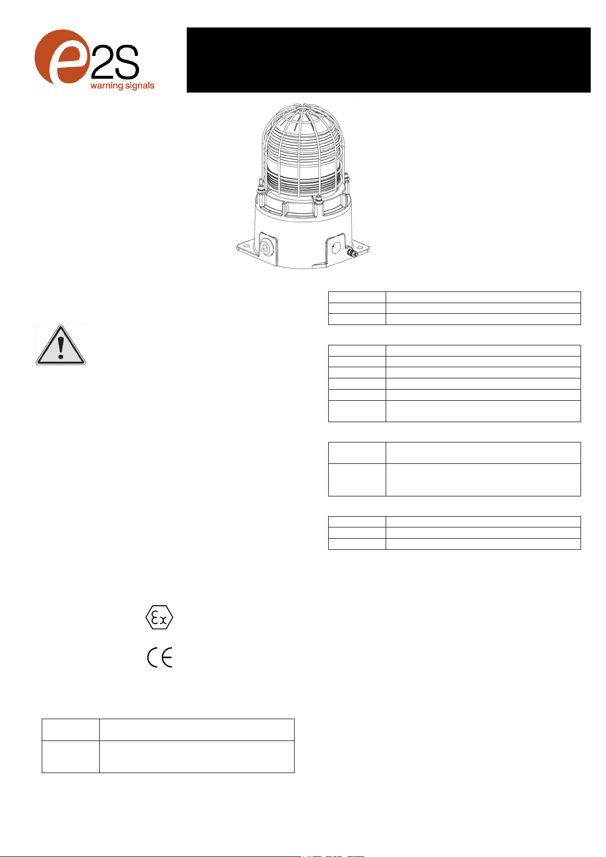
Fig. 2: Accessing the Explosion proof Enclosure
On completion of the installation the flameproof threaded joint
should be inspected to ensure that they are clean and that
they have not been damaged during installation. Flameproof
threaded joints are not intended to be repaired. Also check
that the ‘O’ ring seal is in place. When fitting the flameproof
cover ensure the thread is engaged correctly. Fully tighten
the cover all the way, ensure no gap is visible between the
cover and base of the beacon enclosure. Tighten the M4
grub screw.
8) Power Supply Selection
It is important that a suitable power supply is used to run the
beacons. The power supply selected must have the
necessary capacity to provide the input current to all of the
beacons
The following table shows the input current taken by the
various beacons:
The equipment has been tested for supply voltage variation
of -30% / +25% according to DNVGL-CG-0339.
9) Selection of Cable, Cable Glands, Blanking
Elements & Adapters
When selecting the cable size, consideration must be given
to the input current that each unit draws (see table above),
the number of beacons on the line and the length of the cable
runs. The cable size selected must have the necessary
capacity to provide the input current to all of the beacons
connected to the line.
For ambient temperatures over +40ºC the cable entry
temperature may exceed +70ºC and therefore suitable heat
resisting cables and cable glands must be used as per table
below
STExB2LD2
Ambient
Temp. 45ºC 50ºC 55ºC 60ºC 65ºC 70ºC
Min. Rating of
cables and
cable glands
85ºC 90ºC 95ºC 100ºC 105ºC 110ºC
The cable entries have an M20 x 1.5 – 6H entry thread. If the
installation is made using cable glands, only suitably rated
and ATEX / IECEx certified cable glands must be used. They
must be suitable for the type of cable being used and also
meet the requirements of the current installation standards
EN 60079-14 / IEC60079-14.
Any unused cable entries must be closed with suitably rated
and ATEX / IECEx certified blanking plugs.
If the installation is made using conduit, openings must have
a sealing fitting connected as close as practical to the wall of
the enclosure, but in no case more than the size of the
conduit or 50mm, whichever is the lesser.
If a high IP (Ingress Protection) rating is required then a
suitable sealing washer must be fitted under the cable glands
or blanking plugs. A minimum ingress protection rating of
IP6X must be maintained for installations in explosive dust
atmospheres.
For combustible dust applications, the cable entry device and
blanking elements shall be in type of explosion protection and
shall have an IP 6X rating.
The STEx Beacon Range can be supplied with the following
types of adapters:
M20 to ½” NPT
M20 to ¾” NPT
M20 to M25
It is important to note that stopping plugs cannot be fitted
onto adapters, only directly onto the M20 entries.
Any other adapters used must be suitably rated and ATEX /
IECEx certified adapters.
10) Earthing
Both AC and DC beacon units must be connected to an earth
according to EN/IEC 60079/14. The units are provided with
internal and external earth terminals which are both located
on the terminal chamber section of the unit
Internal earthing connections should be made to the Internal
Earth terminal in the base of the housing using a ring crimp
terminal to secure the earth conductor under the earth clamp.
The earth conductor should be at least equal in size and
rating to the incoming power conductors.
External earthing connections should be made to the M5
earth stud, using a ring crimp terminal to secure the earth
conductor to the earth stud. The external earth conductor
should be at least 4mm² in size.
Type No.
STExB2LD2
Flash Modes
Nominal Current
Nominal Voltage Steady High
Powe
r
Steady Low
Powe
r
Flashing
1Hz
24Vdc 240mA 134mA 110mA
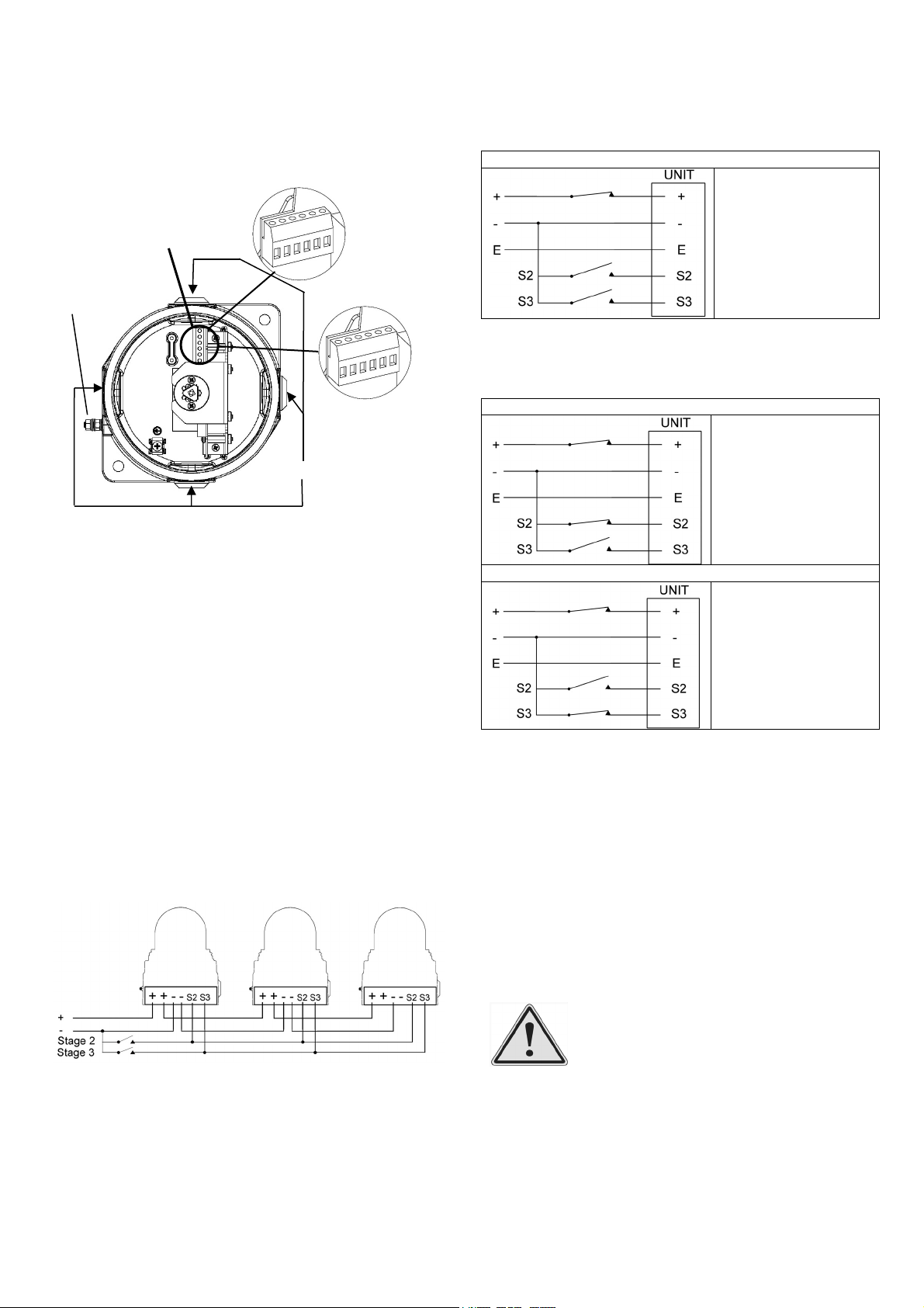
M4 x 12mm
Grub Screw
Lid
Moulding
O-Ring

_______________________________________________________________________________________________________________________________
European Safety Systems Ltd. Impress House, Mansell Road, Acton, London W3 7QH [email protected] Tel: +44 (0)208 743 8880
www.e2s.com Fax: +44 (0)208 740 4200
Document No. D199-00-411-IS-SC Issue 4 24-02-2021 Sheet 4 of 6
Customer Supplied
Switch
11) Cable Connections
Electrical connections are to be made into the terminal blocks
on the PCBA located in the flameproof enclosure. See
section 7 of this manual for access to the flameproof
enclosure.
Fig. 3: STExB2LD2 Entries and Terminal Block Location
Wires having a cross sectional area between 0.5 mm² to
2.5mm² can be connected to each terminal way. If an input
and output wire is required the 2-off Live/Neutral or +/-
terminals can be used. If fitting 2-off wires to one terminal
way the sum of the 2-off wires must be a maximum cross
sectional area of 2.5mm². Strip wires to 8mm. Wires may also
be fitted using ferrules. Terminal screws need to be tightened
down with a tightening torque of 0.45 Nm / 5 Lb-in. When
connecting wires to the terminals great care should be taken
to dress the wires so that when the cover is inserted into the
chamber the wires do not exert excess pressure on the
terminal blocks. This is particularly important when using
cables with large cross sectional areas such as 2.5mm².
12) DC Wiring
A 6-way terminal block is provided on the AC Beacon. There
are 2-off +ve, 2-off –ve, 1-off S2 and 1-off S3 terminals in
total.
12.1 Wiring Diagram
Fig. 4: STExB2LD2DC Simplified Block Diagram
12.2 Stage Switching
12.2.1 Units First Stage Flash Patterns
Stage two (S1) Operation
Power +ve and –ve,
Dip switch alters stage
1 tone.
12.2.2 DC Units Second and Third Stage Flash
Pattern Selection
For units set up for –ve switching (default setting):
Stage two (S2) Operation
Power +ve and –ve, link
a -ve supply line to the
S2 terminal.
Dip switch alters stage 2
tone.
Stage three (S3) Operation
Power +ve and –ve, link
a -ve supply line to the
S3 terminal.
Dip switch alters stage 3
tone.
12.2 End of Line monitoring (DC Units)
On the STExB2LD2 DC beacons, dc reverse line monitoring
can be used if required. All DC units have a blocking diode
fitted in their supply input lines. An end of line monitoring
diode or an end of line monitoring resistor can be connected
across the +ve and –ve terminals in the flameproof chamber.
If an end of line resistor is used it must have a minimum
resistance value of 3k3 ohms and a minimum wattage of
0.5W or a minimum resistance value of 500 ohms and a
minimum wattage of 2W.
13) Settings
13.1 Flash Patterns
The STExB2LD2 beacons can produce different flash
patterns as shown in Table 1. The flash patterns are selected
by operation of the flash setting DIP switch on the PCB, Fig
6.
Warning – high-intensity light source. Avoid
looking directly at the light source for
extended periods of time.
AC Units
DC Units
M20 x 1.5 Entries
External Earth
Stud
Input Terminal
L
L
E NN
-
-
+
+
E
S2
S3

_______________________________________________________________________________________________________________________________
European Safety Systems Ltd. Impress House, Mansell Road, Acton, London W3 7QH [email protected] Tel: +44 (0)208 743 8880
www.e2s.com Fax: +44 (0)208 740 4200
Document No. D199-00-411-IS-SC Issue 4 24-02-2021 Sheet 5 of 6
Fig. 5: DIP Switch Location
Table 1: Switch Positions for Flash Patterns
13.2 Synchronised Operation
All STExB2XLD2 beacons that are connected to the same
supply line and have the same flash pattern selected will
have a synchronised flash rate, see Figure 5.
14) Interchangeable & Spare Parts
The beacon lens are interchangeable, contact European
Safety Systems Ltd for a replacement lens available in
various colours.
The guard is an integral part of the protection and must be
reassembled exactly the same way as it was disassembled.
To change the lens, unscrew the M5 socket head screws and
remove the M5 screws, M5 spring & flat washers.
Fig 6. Removal of Lens
Remove the guard and replace the old lens with the new
lens.
Fig 7. Changing of Lens
Fit the guard back on to the lens and casting, align the holes
of the guard, lens and casting. To reattach the lens, the
fixings MUST be in the order shown in figure 6.
Fig 8. Lens & Guard fixings order
Switch
Setting S1 Mode S2 Mode S3 Mode
(123456) ( & ) ( Only) ( Only)
000000 Steady High
Powe
r
Flashing 1Hz Flashing Triple
Strike
000001 Steady Low
Power Flashing 1Hz Flashing Triple
Strike
100000 Flashing 1Hz Flashing
Double Strike
Flashing Triple
Strike
101000 Flashing
1.5Hz Flashing 2Hz Flashing
Double Strike
010000 Flashing 2Hz Flashing Triple
Strike
Flashing Triple
Strike
110000 Flashing
Double Strike
Steady High
Power
Flashing Triple
Strike
001000 Flashing
Triple Strike Flashing 2Hz Flashing
Double Strike
Warning – Hot surfaces. External surfaces
and internal components may be hot after
operation, take care when handling the
equipment.
M5x16 Hex
Socket Screw
Old Lens
New Lens
M5x16 Hex Socket Screw
M5 Spring Washer
M5 Plain Washer
Guard
Lens
Example Shown:
100000 =
Flashing 1Hz

_______________________________________________________________________________________________________________________________
European Safety Systems Ltd. Impress House, Mansell Road, Acton, London W3 7QH [email protected] Tel: +44 (0)208 743 8880
www.e2s.com Fax: +44 (0)208 740 4200
Document No. D199-00-411-IS-SC Issue 4 24-02-2021 Sheet 6 of 6
15) Maintenance, Overhaul and Repair
Maintenance, repair and overhaul of the equipment should
only be carried out by suitably qualified personnel in
accordance with the current relevant standards:
EN60079-19/IEC60079-19
Explosive atmospheres – Equipment repair, overhaul and
reclamatio
EN 60079-17/IEC60079-17
Explosive atmospheres – Electrical installations inspection
and maintenance
Units must not be opened while an explosive atmosphere is
present.
If opening the unit during maintenance operations a clean
environment must be maintained and any dust layer removed
prior to opening the unit.
Flameproof threaded joints and cemented joints are not
permitted to be repaired.
Electrostatic charging hazard - Clean only with a damp cloth.

E2S Telephone: +44 (0)20 8743 8880 Fax: +44 (0)20 8740 4200 Email: [email protected] www.e2s.com DC-070_Issue_F (STEx) - Page 1 of 2 - QAF_252_Issue_5
EU Declaration of Conformity
Manufacturer: European Safety Systems Ltd.
Impress House, Mansell Road, Acton
London, W3 7QH
United Kingdom
Authorised Representative: E2S Warnsignaltechnik UG
Charlottenstrasse 45-51
72764 Reutlingen
Germany
Equipment Type: STExS1, STExS2, STExL1, STExL2
STExB2X10, STExB2X15, STExB2X21
STExB2LD2, STExB2RT1
STExC1X05
STExJ2
Directive 2014/34/EU: Equipment and Protective Systems for use in Potentially Explosive Atmospheres (ATEX)
Notified Body for EU type Examination (Module B):
UL International Demko A/S
Notified Body No.: 0539
Borupvang 5A, 2750 Ballerup, Denmark
EU-type Examination Certificate (Module B):
DEMKO 16ATEX1466X
Notified Body for Quality Assurance Notification / Conformity to EU-type
based on
quality assurance of the production process (Module D):
Sira Certification Service
Notified Body No.: 2813
CSA Group Netherlands B.V, Utrechtseweg 310, 6812 AR, Arnhem, Netherlands
Quality Assurance Notification (Module D):
SIRA 05 ATEX M342
Provisions fulfilled by the equipment:
II 2G Ex db IIC T6…T3 Gb
II 2D Ex tb IIIC T85°C…T135°C Db
IP6X Dust Protection to EN60079-0 / EN60079-31
Standards applied:
EN 60079-0: 2012 / A11: 2013
EN 60079-1: 2014
EN 60079-31: 2014
Directive 2014/30/EU: Electromagnetic Compatibility Directive (EMC)
Standards applied:
EN 61000-6-1:2007
EN 61000-6-2:2005
EN 61000-6-3:2007 / A1:2011 / AC: 2012
EN 61000-6-4:2007 / A1: 2011
Directive 2011/65/EU: Restriction of the use of certain hazardous substances in electrical and electronic equipment (RoHS)
The product and all the components contained within it are in accordance with the restriction of the use of hazardous substances in electrical and electronic
equipment, including amendment by Directive 2015/863/EU.
Regulation (EC) 1907/2006: Registration, Evaluation, Authorisation and Restriction of Chemicals (REACH)
The product and all the components contained within it are free from substances of very high concern.
Other Standards and Regulations
EN 60529:1991 / A1:2000 / A2:2013 - Degrees of protection provided by enclosures (IP code) –enclosure rated IP66

E2S Telephone: +44 (0)20 8743 8880 Fax: +44 (0)20 8740 4200 Email: [email protected] www.e2s.com DC-070_Issue_F (STEx) - Page 2 of 2 - QAF_252_Issue_5
Martin Streetz
Document No.:
DC-070_Issue_F
Quality Assurance Manager
Date and Place of Issue:
London, 23/12/2020
EU Declaration of Conformity
On behalf of European Safety Systems Ltd., I declare that, on the date the equipment accompanied by this declaration is placed on the market, the equipment
conforms with all technical and regulatory requirements of the above listed directives, regulations and standards.
This Declaration is issued under the sole responsibility of the manufacturer.
Other manuals for STExB2LD2
2
Table of contents
Other E2S Marine Equipment manuals

E2S
E2S A112N User manual

E2S
E2S BExS110D User manual

E2S
E2S A100 AlertAlarm User manual

E2S
E2S E2XS112UL User manual

E2S
E2S BEXCS11005D230AC-AM User manual

E2S
E2S E2 S121UL Series User manual

E2S
E2S A100SONTEL User manual

E2S
E2S STExS1 User manual

E2S
E2S D105 AlertAlarm User manual

E2S
E2S BExCTS110-05D-P User manual

E2S
E2S IS-pA1 User manual

E2S
E2S Sontel BExTS110DAC115 User manual

E2S
E2S D1xS2 Series User manual

E2S
E2S GNExS1 User manual

E2S
E2S GNExS2F User manual

E2S
E2S BExCS110-05D-PDC012 User manual

E2S
E2S GNExS2 User manual

E2S
E2S D1xS1 Series User manual

E2S
E2S SONF1 Series User manual

E2S
E2S BExDTS110D User manual