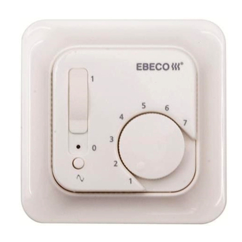
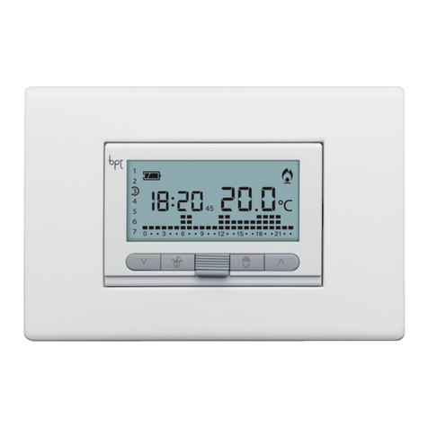
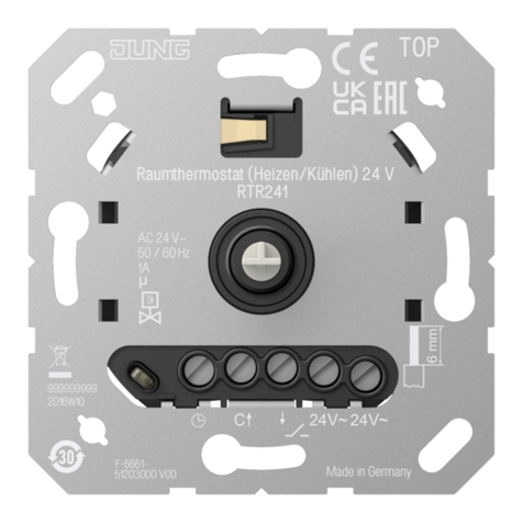
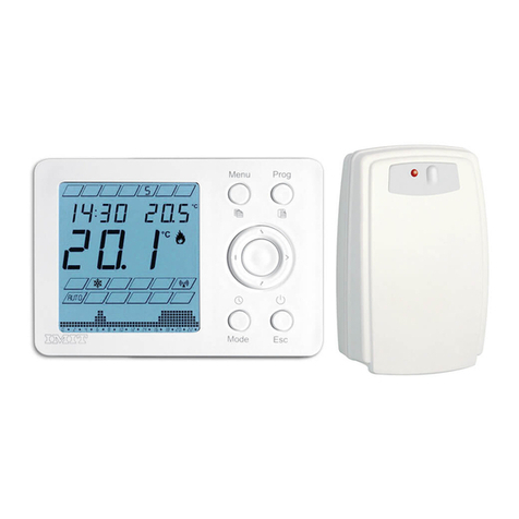
EBECO EB-Therm 300 User manual

EB-Therm 300
E 85 816 65 / SSTL 35 304 74
MONTERINGSANVISNING / INSTALLATION INSTRUCTIONS
LEGGEANVISNING / ASSENNUSOHJEET
051019
Lärjeågatan 11 •S-415 25 Göteborg
•
SWEDEN
•
Tel +46 31 707 75 50

Golvgivare/Floor sensor (NTC)
Temp (°C) Value (kOhm)
10°C 19,9 kOhm
15°C 15,7 kOhm
20°C 12,5 kOhm
25°C 10,0 kOhm
30°C 8,0 kOhm
+
-+
-+
-+
-+
-+
-
Fig 7
Fig 6
a)
a)
c)
b) Fig 1 Fig 2
Fig 3 Fig 4 Fig 5

+
-
+
-
+
-
+
-
+
-
+
-
+
-
+
-
+
-
+
-
+
-+
-
+
-
+
-
Fig 8 Fig 9
Fig 10
Fig 11
Fig 12

+
push button
and wait 4
seconds
push button
and wait 4
seconds
Fig 14
Fig 15
+
Fig 16
Fig 17
Fig 13

- ENGLISH -
Installation instructions
Description
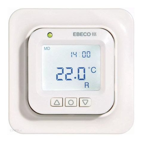
EB-Therm 300 is an electronic thermostat with LCD display. The thermostat
has three separate temperature control functions. You can choose between
room thermostat, floor thermostat or room thermostat with overheat
protection in the floor. The thermostat has three temperature setback
programs: two of them are pre-programmed (for homes or offices) and one
is for user settings. The EB-Therm 300 is approved for installation in wet
rooms, SEMKO-certified and CE-marked. The thermostat is designed for
flush or surface mounting. The front panel has an LCD display (Fig 1a), a
dual-function LED (Fig 1b) and a dual-function knob (Fig 1c). Settings and
temperature readings are shown digitally and graphically on the display (Fig
1a).
Fuzzy technology
Temperature regulation is based on an algorithm, which uses fuzzy
technology. This means that the thermostat collects data from the start and
calculates when it should switch on and off on the basis of that data. This
approach reduces temperature fluctuations, providing a more uniform
temperature and lower energy consumption. The temperature in the floor
varies by less than +/- 0.2 degrees. See the diagram below.
Installation
Flush mounting - EB-Therm mounts in a standard 65 mm mounting box.
The location should be chosen so that the thermostat is protected from
direct sunlight and draughts. The floor sensor must be installed in a conduit
laid in the floor. The end of the conduit must be sealed to make it easy to
change the floor sensor. All incoming conduits to the mounting box must be
sealed so that the air temperature sensor is not affected by draughts.
1. Make sure that the mounting box is flush with the wall.
2. Remove the setting knob. Press the latch (Fig 2a) and lift of the
front cover and the frame.
3. Connect 230 V AC electric power, the load and the floor sensor
cable. If the floor sensor cable needs to be extended,use
power wiring. Connect the protective conductor for the incoming
supply and for the heating cable with a terminal block in the box
(Fig 3).
4. Place the thermostat in the mounting box and secure it with the
screws provided.
5. Refit the frame, front cover and setting knob.
Mounting with distance frame - (E 85 816 68), (Fig 4). Fix the distance
frame to the wall with screws. Then install the thermostat, following the
instructions above.
Mounting in a wet room – Install the IP 21 gasket (21 066 57) (Fig 5).
Settings
General
To return to the main menu from any menu, press EXIT. Exception: when
choosing the lock.
Key to symbols in diagrams:
Description of display
See the diagram below for a description of the display functions.
a, b– set temperature (set point)
c– measured temperature (actual value)
d– the arrow indicates that the temperature setback program is running
e– the key indicates that the temperature settings are locked
f– the symbol shows which thermostat function is set:
”&” – room thermostat with overheat protection in the floor
“F” – floor thermostat
“R” – room thermostat
+
-°C
a
c
d
e
f
b
Temperature
Turning the knob clockwise increases the desired temperature (set point);
turning it anticlockwise reduces it. The actual value reading (the current
temperature of the floor or of the room) may differ from a thermometer
reading, owing to the properties of the room (underfloor heating design,
room insulation, etc.).
Time and date
The thermostat shows the time and the date. The calendar adjusts
automatically for leap years and for summer/winter time. Before the
temperature setback program can be used, the time and date must be set.
This is done as follows (Fig 6):
- press the knob once
- turn, choose
SETTINGS and press
- turn , choose SET CLOCK and press
- set year, month, day, time and summer/winter time by turning and
pressing the knob
Thermostat settings
The EB-Therm can provide three distinct functions.
• “R&F” = room and floor thermostat - a built-in sensor regulates the
room temperature between 5°C and 37°C. The external floor sensor
operates as a floor temperature limiter. The limit can be set from 5°C
to 45°C. The factory setting is 27°C.
• “F” - floor thermostat (factory setting) – The external floor sensor
regulates the floor temperature. The preset value is 22°C.
• “R” - room thermostat – A built-in sensor regulates the room
temperature. This function cannot be chosen when the floor sensor is
connected. If the floor sensoris not connected when the system is
switched on for the first time, the thermostat chooses this function
automatically.
Functions are chosen as follows (Fig 7):
- press the knob once
- turn, choose
SETTINGS and press
- turn, choose
THERMOSTAT MODE and press
- choose the required function (R&F/F/R) and press
Overheat protection – This function protects the floor from overheating. The
factory setting of the overheat protection (27°C) can be changed. This is
how to set the temperature limiter for an external floor sensor (Fig 8):
- press the knob once
- turn, choose
SETTINGS and press
- turn, choose
OVERHEAT PROTECT and press
- set the required temperature by turning and pressing the knob.
turn the
knob press the knob
once
Floor temperature
Time (minutes)
18
20
22
24
26
28
30
12,5
25,5
38,5
51,5
64,5
77,5
90,5
104
117
130
143
156
169
182
195
208
221
234
247
Tid ( i t )
Temp
(C)
Temp.
(C)

- ENGLISH -
Programming - preset programs
The thermostat has two built-in temperature setback programs which are
suitable for the home or office environment.
Program for the home environment. The temperature is reduced
automatically by 5 degrees C at the following times:
Mon - Fri 08:30 - 15:00
Mon - Sun 23:00 - 05:00
Program for the office environment. The temperature is reduced
automatically by 5 degrees C all the time except:
Mon - Fri 05:00 - 18:00
The temperature setback program is chosen as follows (Fig 9):
- press the knob once
- turn, choose
PROGRAM SELECT and press
- turn, choose the desired function HOME/OFFICE/USER
(home, office or user) and press.
Programming - user settings
EB-Therm 300 also has programs for user settings. You can setfour events
during Monday to Friday and two events during Saturday and Sunday. If the
required temperature is changed manually when a function is active, the
program resumes operating after the setting at the next event. This is how
to do user settings (Fig 10):
- press the knob once
- turn, choose
SETTINGS and press
- turn, choose
SET USER PROGRAM and press
- turn, choose period 4EV M-Ffor Mon-Fri or 2EV W-Efor
Sat-Sun
- set time and required temperature TIME/TEMP when each
event is to begin, by turning and pressing the knob.
Display
The display contrast can be set to suit individual preference as follows (Fig
11):
- press the knob once
- turn, choose
DISPLAY and press
- turn, choose
SET CONTRAST and press
- set the required contrast by turning the knob, then press.
Time and date – This function shows the current time and date on the
display as follows (Fig 12):
- press the knob once
- turn, choose
DISPLAY and press
- turn, choose
SHOW DATE/TIME and press.
Current settings – This function shows the currentsettings on the display as
follows (Fig 13):
- press the knob once
- turn, choose
DISPLAY and press
- turn, choose
SHOW USER PROG. and press
- turn, choose 4EV M-F(four events) or 2EV W-E(two
events) and press
- turn the knob to show each event with the set date and
temperature, SHOW PROGRAM.
- press the knob once to return to the previous menu.
Power on/off
This function put the underfloorheating system in standby mode. It is
activated as follows (Fig 14):
- press the knob and keep it pressed for about four seconds
Locking function
This is how to lock the chosen temperature and other settings (Fig 15):
- press the knob once
- turn, choose
LOCK and press
- turn, choose
LOCK and press
- a key which locks the temperature appears on the display with
thermometer
This is how to unlock the temperature settings (Fig 16):
- press the knob and keep it pressed
- turn the knob clockwise until the key disappears
Fault message
This function indicated when faults have occurred. When faults occur, the
thermostat contact opens and the LED starts to flash alternately green-red.
You can also read the nature of the fault by using the diagnostic display of
the thermostat, as shown in Figure 17.
- press the knob once
- turn, choose
DISPLAY and press
- turn, choose
DIAGNOSTICS and press
The diagnostic display shows the status of the sensors. Description of the
diagnostic display:
a– floor sensor
b– room sensor
c– internal sensor
d– sensor working properly
e– sensor not working – open circuit
f – sensor not working – short circuit
If a fault is indicated on sensor (b) or (c), replace the thermostat. If a fault is
indicated on sensor (a), replace the floor sensor. If the floor sensor (a) is
faulty, the thermostat can only work as a room thermostat, and only if the
user changes the thermostat function from floor or floor/room thermostat to
room thermostat. If a sensor is damaged or open circuit, the thermostat
contact opens, the LED starts to flash (twice a second) anda fault message
is displayed. If the floor sensor is faulty it must be replaced. If the room
sensor is faulty, the thermostat must be replaced.
Technical data
Voltage 230 VAC±10% 50-60Hz
Air temperature range +5°C to +37°C
Floor temperature range +5°C to +37°C
Temperature limiter +5°C to +45°C
Breaking capacity 250 V 16 A
Connecting cable max 2.5 mm²
Load Cos φ= 0.3 max
Hysteresis ±0.5°C
Ambient temperature 0°C to +60°C
Degree of protection IP21
Running reserve* 12 hours
Colour Polar white
Max. length of sensor cable 50m, 2x1.5mm²
Graphical LCD display 96x24 dots
Indication:
230 V supply connected Green LED
Heating cable operating Red LED
Suitable for Eljo Trend, Elko RS, Strömfors and Merten frame systems.
EMC certified. Withstands a surge of 2500 V AC.
* Time the programmed settings arepreserved in thethermostat inthe event of power failure, for
instance
EB-Therm 300 with accessories
Art. no. Article Dimensions (mm)
E 85 816 65 EB-Therm 300* 81x81x40
E 85 816 68 Distance frame 81x81x18
E 85 816 71 Sensor cable* 3 m
21 066 48 Front cover for Eljo Trend*
21 066 51 Front cover for Eljo RS*
21 066 57 IP21 gasket*
66 210 54 Frame for Eljo Trend*
66 210 56 Frame for Strömfors*
14 408 80 Terminal*
E 85 816 76 Front cover, aluminium
E 85 816 77 Front cover, bronze
*Included in the pack
a
b
c
d
e
f
Table of contents
Other EBECO Thermostat manuals

EBECO
EBECO EB-Therm 30 User manual

EBECO
EBECO EB-Therm 205 User manual
EBECO
EBECO EB-Therm 355 User manual

EBECO
EBECO EB-Therm 500 User manual

EBECO
EBECO EB-Therm 350 User manual

EBECO
EBECO EB-Therm 800 User manual

EBECO
EBECO EB-Therm 800 User manual
EBECO
EBECO EB-Therm 205 User manual

EBECO
EBECO EB-Therm 800 User manual

EBECO
EBECO EB-Therm 55 User manual
Popular Thermostat manuals by other brands
Honeywell
Honeywell RTH7400 series installation guide
Heatmiser
Heatmiser SLIMLINE user manual

White Rodgers
White Rodgers 1F82-51 Installation and operation instructions

NOBOCOOL
NOBOCOOL R80-UDF User instruction
Honeywell
Honeywell FocusPRO TH6220D installation guide
Grasslin
Grasslin thermio essential BCP Operation instructions


