Ecleris STROBOLIGHT User manual

USER MANUAL
STROBOLIGHT
LARYNGOSTROBOSCOPE
ABOUT THIS MANUAL
Version: 2019.04.01
Year: 2019
Language: English
All the rights to this manual are reserved, especially reproduction, publication and translation rights. No portion of this manual may be
reproduced by no means (photocopy, microfilm or other methods) without previous written authorization from ECLERIS. Neither can it
be reproduced, multiplied or published through any electronic data processing form.
The information contained in this manual may be modified or broaden without previous notification, without it representing any
responsibility to ECLERIS.
ECLERIS USA.
11801 NW 100th Rd
Suite 17
Medley, FL 33178
Phone: +1 786 483 7490
CMC Medical Devices & Drugs S.L.
C/ Horacio Lengo Nº18, CP29006,
Málaga, Spain
Ph. +34951214054

USER MANUAL –STROBOLIGHT
Page 2of 15
INMANUUIN187 Rev.2019.04.01 / ENG
TABLE OF CONTENT
1. SYMBOLS................................................................................................................................3
2. SECURITY WARNINGS ..........................................................................................................3
3. DESCRIPTION.........................................................................................................................4
3.1 INTENDED USE...................................................................................................................4
3.2 INTENDED USER ................................................................................................................4
3.3 DESCRIPTION AND FUNCTIONING...................................................................................4
3.3.1. PARAMETERS TO BE ASSESSED BY STROBOSCOPY.................................................5
3.4 COMPONENTS....................................................................................................................5
3.4.1 FRONT PANEL .............................................................................................................6
3.4.2 REAR PANEL................................................................................................................6
4. INSTALLATION AND SET UP .................................................................................................6
4.1 GENERAL CONSIDERATIONS ...........................................................................................6
5. REVISION AND OPERATION..................................................................................................7
5.1 REVISION............................................................................................................................7
5.2 OPERATION........................................................................................................................7
5.3 EQUIPMENT CONTROLS SPECIFICATIONS.....................................................................8
5.3.1 FRONT PANEL .............................................................................................................8
6. PERFORMING AN EXAMINATION..........................................................................................9
6.1 GENERAL CONSIDERATIONS ...........................................................................................9
6.2 PREPARING THE PATIENT ................................................................................................9
6.3 INTRODUCING THE ENDOSCOPE.....................................................................................9
6.4 PATIENT PHONATION........................................................................................................9
6.5 RECOMMENDATIONS ......................................................................................................10
7. MAINTENANCE.....................................................................................................................10
7.1 CLEANING.........................................................................................................................11
7.2 ELECTRICAL CONNECTIONS..........................................................................................11
7.3 LAMP REPLACEMENT......................................................................................................11
8. TECHNICAL SPECIFICATIONS............................................................................................13
9. TROUBLESHOOTING...........................................................................................................14
10. TECHNICAL SERVICE.......................................................................................................14
11. WARRANTY.......................................................................................................................14

USER MANUAL –STROBOLIGHT
Page 3of 15
INMANUUIN187 Rev.2019.04.01 / ENG
1. SYMBOLS
Read the related documentation
This side up
Warning
Fragile
Caution
Protect from water
Alternate current
Temperature limits
Type BF
Pressure Limits
CE mark
Humidity Limits
Dangerous voltage
Do not discard with the
household waste
EU Authorized Representative
Manufacturers information
(Name, Address)
Date of Manufacture
(MM/AAAA)
Serial number
2. SECURITY WARNINGS
The contents of this guide describe the recommended procedures for the proper installation and
use of STROBOLIGHT.
Please read carefully the whole guide before using the equipment.
If you have any doubt regarding the contents of this guide, the use or safety of the equipment,
please contact your local provider or the nearest Ecleris office.
If by any of the following:
Inadequate use of the equipment.
Failure to use the instruction manual.
Bad maintenance and care of the equipment.
Repair or manipulation by unauthorized personnel.
…personal or material damage is produced to a third party, ECLERIS, the manufacturer and
sales agent of this equipment, will not assume responsibility for said damage..
The device should never be discarded with the household waste. Please check local
regulations for electronic components disposal or recycling. It is the user’s
responsibility to deliver the system to the proper location for disposal or recycle of
electrical and electronic devices.

USER MANUAL –STROBOLIGHT
Page 4of 15
INMANUUIN187 Rev.2019.04.01 / ENG
3. DESCRIPTION
3.1 INTENDED USE
The StroboLIGHT is intended to be used in laryngostroboscopy and endoscopic procedures in
ORL.
3.2 INTENDED USER
The StroboLIGHT has been designed to be used by medical, paramedical or health professionals.
3.3 DESCRIPTION AND FUNCTIONING
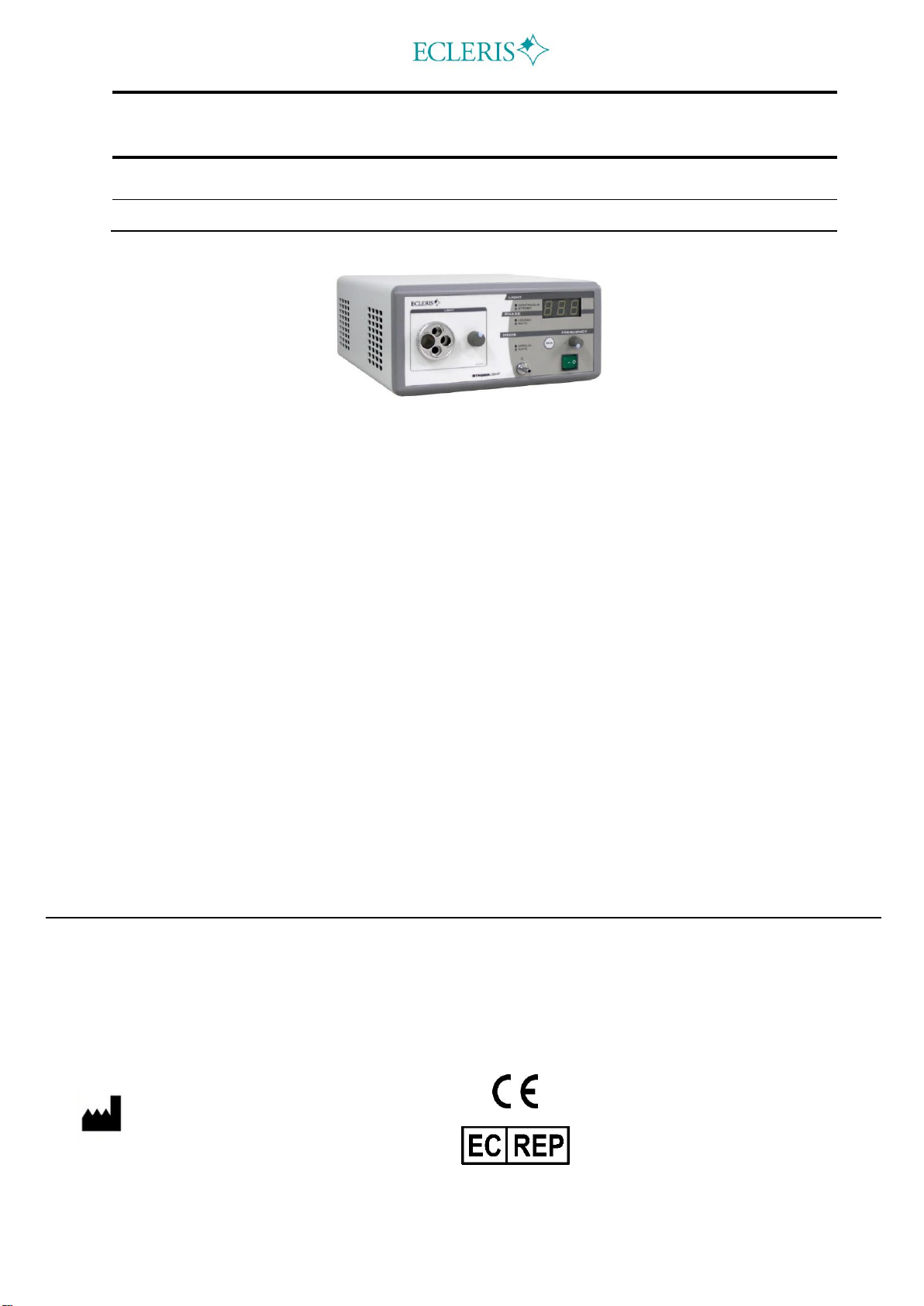
STROBOLIGHT stroboscope has a Xenon arc lamp, and has been designed to be used in
Laryngostroboscopy as well as in endoscopic procedures, due to its versatility to provide, using
the same lamp, completely continuous and stroboscopic light.
The STROBOLIGHT has a lighting module with a 180 Watts Xenon lamp which produces the
necessary light to obtain video images. The cold, deep and white Xenon light of this equipment
enhances the real brightness and colors allowing its use for all types of stroboscopic and
endoscopic procedures.
The manually operated mechanical diaphragm with continuous adjustment allows regulating the
lighting level so that the user gets the necessary optimum level, always keeping the same lighting
quality and color temperature.
Stroboscopy makes it possible to study laryngeal physiology and pathophysiology, as well as to
perform a comprehensive diagnosis of its changes.
To understand the principles of how a stroboscope works it is essential to be familiar with the
phonation process.
Phonation is the physical act of producing sound by the passive interaction of the vocal folds and
exhaled air it is modified in terms of tone, pitch and intensity by thoracic, abdominal and laryngeal
muscles, and by the cavities in the upper respiratory tract.
At the beginning of the vibration cycle, the vocal folds are closed at the middle line; when the
subglottal pressure exceeds, by volitive effect, the resistance created by the closure of the vocal
folds, the inferior border begins to open and this aperture generates an undulating movement of
the folds from the inferior to the superior border with a resultant aperture and closure sequence.
Expiratory muscle contraction results in an increase of subglottal pressure and passing of air
between the vocal folds that come together to the middle line, thus preventing air stream to pass
through and the cycle begins once again. Stroboscopic effect is based on the optical illusion that
creates a fictitious slowing down of a periodical movement, which makes it possible to display fold
vibration.
Stroboscopic light sends rapid pulses, each of them flashing a particular point in the vibration
cycle. Whenever the frequency is changed regarding fold vibration (asynchronic), an optical
illusion of movement occurs; whenever both frequencies overlap (synchronic), a frozen or still
movement effect occurs. When the emission of flash and the phonation frequency are synchronic,
the same part of the fold vibration cycle will be flashed, therefore vocal cords will be seen
motionless or in slow motion due to phase variation.
However, when the emission of flashes is asynchronic, a different stage of the vibration cycle will
be lit up with each flash impulse.

USER MANUAL –STROBOLIGHT
Page 5of 15
INMANUUIN187 Rev.2019.04.01 / ENG
Laryngostroboscopy goals:
Vocal folds observation
Prognosis assessment
Results monitoring
For a proper use of STROBOLIGHT it is essential to know the basic functioning of the equipment.
3.3.1. PARAMETERS TO BE ASSESSED BY STROBOSCOPY
It is essential to know the parameters that have to be evaluated by stroboscopy. The different
parameters are briefly discussed below.
Mucosa wave: The main feature of the vibration movement is an out-of-phase between the upper
and lower lips of the vocal folds and it is perceived as a mucosa wave traveling in a down-up and
in-out direction (varying according to phonation intensity and tone). Normal variations depend on
sound intensity and frequency used.
Symmetry: In a normal larynx, vocal folds display a mirrored image. Asymmetry involves different
mechanical properties. It is believed that folds are out of phase when one of them remains in the
aperture phase while the other is closed or in a closure phase.
Periodicity: It refers to the regularity of the successive cycles of fold vibration. Aperiodicity
becomes evident by presence of sound at the time of emission.
Amplitude: It refers to the amplitude of vocal folds on the horizontal plane. The higher the
subglottal pressure and lower the fundamental frequency, the larger the amplitude. It can be
impaired under conditions such as vocal fold stiffness (a reduction in the lateral movement is
observed) or increased by presbyphony or paralysis (wide lateral amplitude).
Glottal closure: It assesses the glottal area at the closure phase of the vocal cycle, which can be
complete or incomplete with certain variations. A predominant aperture or closure phase can be
observed.
In summary, some normal vibration findings could be considered:
Periodic vibration.
Symmetric aperture.
Symmetric wave and amplitude.
Different phase between upper and lower lips of vocal folds.
Aperture and closure glottal cycle.
3.4 COMPONENTS
STROBOLIGHT includes the elements and components shown below which are necessary for its
installation.
You should identify and check such elements and components before proceeding with the
equipment installation.
Main Unit
Contact Microphone
Pedal
Power Cord
User’s Guide
Fiber optic cable (Optional)

USER MANUAL –STROBOLIGHT
Page 6of 15
INMANUUIN187 Rev.2019.04.01 / ENG
Ecleris Procam video camera (Optional)
It is advisable to use endoscopes and accessories that meet IEC60601-1 and IEC60601-
2-18 regulations.
3.4.1 FRONT PANEL 1. Frequency control (Manual
Mode)
2. On/Off Switch
3. Contact microphone
connector
4. Diaphragm control
5. Universal fiber optic cable
connector
6. Manual/Auto Mode switch
7. Fundamental Frequency
display (F0)
3.4.2 REAR PANEL
8. Amplified Audio Output
9. 110/220 Voltage Selector
10. Power Cord Connector Fuse
Holder
11. Connector for pedal
12. Lamp calibration control
(Only for Technical Service
purposes)
4. INSTALLATION AND SET UP
4.1 GENERAL CONSIDERATIONS
Before installing the equipment it is important that you carefully read the whole guide. If you have
any doubt regarding the functioning and installation of the equipment, contact your local provider.
Check that you have each of the components and accessories of the equipment..
Important: The equipment must be turned off during this process.
1) Depending on the country, select the voltage of the power source from the 220V/110V
Selector at the back side of the unit (9).
2) Important: Connect the pedal to the 5-pine female Canon Connector located at the back
side of the equipment (11).

USER MANUAL –STROBOLIGHT
Page 7of 15
INMANUUIN187 Rev.2019.04.01 / ENG
3) Connect one end of the Power Cord to the Power Connector located at the back side of
the unit (10). Connect the other end of the Power Cord to the power inlet.
4) Rotate the universal adapter (5) until the corresponding connector is aligned with the light
output.
5) Connect the fiber optic cable to the corresponding connector of the universal adapter
(depending on the fiber optic to be used). The fiber optic connector shall match perfectly
and not exceed the adapter.
6) Connect the contact microphone to the input connector (3) located in the front panel.
Optional: Connect the 2V P-P Audio output (Female RCA Connector) at the back side of the
equipment (8) to the recording device you may use.
Important:
Power must have a ground cable and must have earth connection circuit. Power Cord must
be properly connected and adjusted to the outlet, since in case of disconnection during an
examination some errors may occur.
The pedal is essential to the proper functioning of the equipment. It must be properly
connected to the equipment.
This equipment must not be used under presence of mixed anesthesia flammable by air,
oxygen or nitrous oxide.
5. REVISION AND OPERATION
5.1 REVISION
Once installation is over and before turning the STROBOLIGHT on, please go through the
following check list:
Verify that the electrical power has its grounding connection in perfect conditions and that
it makes perfect contact with the equipment.
Check that the fuse holder is installed and with the correct fuses in it (2 x T5AL250V for
110V power supply and 2 x T2.5AL250V for 220 V).
Check that the ventilation grid is completely free, without obstruction.
Ensure an adequate air flow.
Verify that there are no water or liquid sources near the equipment that may damage it,
such as gases or flammable emissions in the environment.
All connections shall be made before turning the equipment on.
The STROBOLIGHT shall only be used in places with electrical installations that meet the
local regulations in effect.
If before connecting the STROBOLIGHT any anomaly is detected, please contact the technical
service department of your local distributor or the closest ECLERIS office, prior to its use.
5.2 OPERATION
This section thoroughly describes the equipment start-up and functioning verification procedure. It
is recommended to perform this procedure after installing the equipment and during maintenance
inspections.

USER MANUAL –STROBOLIGHT
Page 8of 15
INMANUUIN187 Rev.2019.04.01 / ENG
The equipment shall only be operated by qualified personnel.
Short On and Off-cycles considerable reduce the lamp useful life.
1) Connect the power supply cable to the equipment and the electrical power.
2) You may begin the procedure after turning the STROBOLIGHT on, by pressing the on/off
switch (2).
The Xenon Lamp takes 2 seconds to turn on after the STROBOLIGHT is ON.
3) Use the diaphragm control (4) to regulate lighting intensity.
4) Once the procedure is over, turn the STROBOLIGHT off in order to maximize the lamp
useful life and energy saving.
The use of Strobolight in Continuous Light Mode for long periods of time will
considerably reduce the lamp's useful life.
5.3 EQUIPMENT CONTROLS SPECIFICATIONS
5.3.1 FRONT PANEL
Light: It indicates the operating function of the stroboscope.
Continuous: Led on. Continuous light. It is used during
access to patient. This mode is automatically activated
when the patient stops phoning or the equipment is
turned on for the first time.
Strobo: Led off. It is automatically activated when the
patient phones, the equipment changes to stroboscope
mode and is synchronized by voice.
Phase: In stroboscope mode, while the patient is phoning, it indicates whether asynchronic or
synchronic mode has been selected (via the pedal).
Auto: Led off. Asynchronic. During the phonation cycle, the vocal fold is seen in slow movement.
The speed of this movement is adjusted through the pedal.
Locked: Led on. Synchronic. Vocal fold is displayed in frozen state. The position of the fold during
phonation cycle is selected through the pedal.
Mode: It indicates the functioning mode of the equipment. Mode is selected through
AUTO/MANUAL touch switch (6) at the front side.
Manual: Led on. The frequency in which light flashes are sent is manually set through the
FREQUENCY(1) potentiometer. This mode is used in case the patient has a weak voice, absence
of voice or very irregular phonation cycle, thus the equipment cannot be used in automatic mode.
Important: To change mode, select the Auto mode through the AUTO/MANUAL touch
switch, if not, the equipment will continue shooting the lamp until it eventually turns off,
thus reducing its useful life.
Auto: Led off. During stroboscopy, the equipment automatically sets the main phonation
frequency, and according to the function it is operating, it automatically determines when light

USER MANUAL –STROBOLIGHT
Page 9of 15
INMANUUIN187 Rev.2019.04.01 / ENG
pulses shall be sent to generate visual display of the desired folds. It is the normal functioning
mode.
6. PERFORMING AN EXAMINATION
6.1 GENERAL CONSIDERATIONS
It is essential to perform a stroboscopic examination in a quiet and noiseless environment; and to
follow the series of steps described in this section:
1) Prepare the patient for the examination.
2) Introducing the Scope.
3) Patient Phonation.
6.2 PREPARING THE PATIENT
It is not recommended to perform this examination on children aged 5 or younger, old patients
with poor respiratory compliance or patients suffering from hoarseness or dysphonia
accompanied by severe respiratory disorders. It is also important to previously inform the patient
about the goal and fundamentals of stroboscopy.
Once the patient is willing to begin the examination, he or she must sit upright with his or her back
lying on the back of the chair.
The neck of the patient must be undressed so that the contact microphone can be placed. The
microphone must be placed at the anterior aspect of the neck, over the cricoid cartilage and
below the inferior border of the thyroid cartilage.
The proper location of the contact microphone can be clearly seen in the pictures.
Important: As it is a contact microphone, you must check that its surface is actually in
contact with the skin. To this end, the tape must be properly adjusted to the patient
neck.
6.3 INTRODUCING THE ENDOSCOPE
When introducing the endoscope whether flexible or rigid endoscopes, the functioning mode must
be Continuous, the mode set when turning it on, and the patient must not phone.
Light intensity can be adjusted with diaphragm control at the front panel.
6.4 PATIENT PHONATION
Once the endoscope is in the proper position, he or she is asked to generate the sound of vowel
“e” as in the word “step” for as long as it may be possible.

USER MANUAL –STROBOLIGHT
Page 10 of 15
INMANUUIN187 Rev.2019.04.01 / ENG
Important: By the use of Pedal 1 you can select the functioning mode or Phase. If you want to
see the cord frozen (synchronous), select the "LOCKED" mode (LED on); and if you want to see
the vocal cord in movement (asynchronous), select the “AUTO” mode (LED off). While in
“LOCKED” mode, the position of the vocal cord is changed with Pedal 2. But while in “AUTO”
mode, the phase movement speed is changed with Pedal 2.
If in the screen appear a discontinuous blinking light during phonation, you can ask the patient to
generate a different vowel sound, such as “i” as in the word “it”, “a” as in the word “car”, “u” as in
the word “blue”, etc.
This is due to the fact that correct automatic voice recognition is not achieved, which may occur
because of low intensity, phonation irregularities, or a quasi-disappearance of the fundamental
frequency, etc. It is also useful that the patient utter a higher-pitched vowel.
Should the voice be practically zero (aphonic patient) or inaudible, the Manual Mode must be
selected through the AUTO/MANUAL touch switch at the front side of the equipment and the
frequency manually selected through the FREQUENCY potentiometer.
6.5 RECOMMENDATIONS
It is really important for the voltage selector (220/110 V) to be in the proper position. A
wrong selection can result in improper functioning or damage.
Read carefully the installation section before installing the equipment.
The equipment must have a proper ground connection circuit.
Lay this equipment on a reliable flat surface, if not, vibrations produced during the use of
the equipment may interfere with the voice.
It is recommended to check the proper condition of the contact microphone. It can be
damaged or cut, thus affecting the normal functioning of the equipment. Given that,
request a replacement to your provider.
ECLERIS is not liable for personal injuries or material damages caused to third-parties as a
consequence of:
incorrect use of the equipment,
non-fulfillment of instructions,
poor maintenance,
repair and operation carried out by non-authorized staff.
7. MAINTENANCE
Occasional precautions and good maintenance are necessary to enhance the equipment
features.

USER MANUAL –STROBOLIGHT
Page 11 of 15
INMANUUIN187 Rev.2019.04.01 / ENG
Contact your local dealer or the closest ECLERIS’s office for the inspection or maintenance of
any device.
Only maintenance works expressly written on this manual are authorized by The Company. The
guarantee will become void if any other work is done without ECLERIS’s consent.
7.1 CLEANING
Before cleaning the StroboLIGHT, disconnect the power cable from the electric power
supply.
To clean the cabinet: Use a dry and soft cloth. If the surfaces are very dirty, use a soft cloth
slightly damp with alcohol. Never allow any liquid to enter the unit.
Contact microphone cleaning: Wipe the microphone with a soft cloth free of lints.
Pedal proper care: Wipe the pedal with a damped soft cloth.
7.2 ELECTRICAL CONNECTIONS
Permanently check the condition of all the electrical components.
Check that there are no:
Cables in bad conditions; cut or torn.
Bad connection of the cable with the socket.
Rusty pins in the connectors.
7.3 LAMP REPLACEMENT
Unplug the power cord and wait until the lamp cools down before its replacement.
DO NOT TURN ON THE STROBOLIGHT WITH THE LAMP DISCONNECTED. IT CAN
RESULT IN IMPROPER FUNCTIONING OR DAMAGE TO THE DEVICE OR USER.
To replace the 180w xenon lamp follow the instructions below.
1) Turn off the equipment and unplug the power supply cable from the unit.
2) Turn the unit upside down and remove all the screws (4 located at the corners) that hold
the cover to the hosing.
3) Turn the unit to normal position and slide the cover as shown in the figure. Remove it
completely.

USER MANUAL –STROBOLIGHT
Page 12 of 15
INMANUUIN187 Rev.2019.04.01 / ENG
4) Disconnect the lamp power supply connector.
5) Remove the lamp holder screw and take away the defective lamp.
6) Place the new 180W xenon lamp in the lamp holder as shown in pictures.
7) Fix the lamp by adjusting the lamp holder screw.
8) Connect the xenon lamp power supply connector (male) to the stroboscope female
connector. Check that the cables are far from the fan.
9) Place the cover back.
Lamp power
connector
Lamp holder
screw

USER MANUAL –STROBOLIGHT
Page 13 of 15
INMANUUIN187 Rev.2019.04.01 / ENG
8. TECHNICAL SPECIFICATIONS
Equipment: Laryngostroboscope Model: SL102 STROBOLIGHT
Equipment Class
I
Grade of protection against water
IPXO
Applicable part type
B
Function Mode
Continuous
Input voltage
110/220VAC
Phase number
1 (single-phased)
Current type
Alternate
Frequencies
50/60 Hz
Consumption
350W
Main fuses
T 5AL / 250V ~ (110 V)T 2.5AL / 250V ~ (220
V)
Service conditions
50ºF –104ºF
30-75% (Ambient Relative Humidity)
700-1060 hPa
Storage and transport conditions
-22ºF –122ºF
10-95% (Ambient Relative Humidity)
500-1060 hPa
Weight (cabinet)
14.3 pounds (6.5 Kg.)
Size (cabinet)
11.8 X 5.5 X 15.16 in (30 X 14 X 38.5 cm)
(width X high X depth)
Lamp
Light Source
Xenon Type (Continuous and Stroboscopy
mode)
Power
180 Watts
Color temperature
6000ºK
Refrigeration
Forced ventilation
Light Intensity Adjustment
Manual. Mechanical diaphragm
Light guide connector cable
Built-in revolving turret with multiple adapters
Compatible with rigid and flexible endoscopes
Frequencies - Working Mode
Working Range
Automatic Mode: 76-1100Hz
Manual Mode: 120-700 Hz
Max. Display Error
+/- 1.5 Hz
This equipment must not be used under presence of mixed anesthesia flammable by air,
oxygen or nitrous oxide.

USER MANUAL –STROBOLIGHT
Page 14 of 15
INMANUUIN187 Rev.2019.04.01 / ENG
9. TROUBLESHOOTING
GENERAL CONSIDERATIONS: Verify that the equipment is “ON” by checking that the light of
the power key is on.
PROBLEM
PROBABLE SOLUTION
The equipment doesn’t turn
on
Check the unit is connected to the power inlet, the voltage
selector is in the proper position and that the equipment is
on.
Check the external fuse of the equipment.
If the problem persists, contact at technical support.
There is no light or is
flashing when there is no
phonation
Check all the connections.
Check that the diaphragm is not completely closed (See
Section Introducing the Endoscope).
If the problem persists, contact technical support.
Interference with other
equipment
In case of interference with other equipment, contact
technical support.
Problems with voice
synchronization
Check the proper location of the microphone (See section
“Preparing the patient”).
Check microphone integrity. If damaged, request a
replacement to your provider.
10. TECHNICAL SERVICE
The STROBOLIGHT must be repaired and/or maintained exclusively by authorized ECLERIS
technical services. We recommend the use of the following procedures to allow for quicker
repair service and replacement of products that are guaranteed.
1) Obtain telephone contact with the technical department of your local distributor or the
nearest Ecleris office.
2) Give detailed information of the problem and the unit serial number.
3) If the problem cannot be resolved by “Troubleshooting”, you must send the products for
their repair.
You must attach the following product information:
Name of owner.
Owner’s address.
Person to contact by phone and phone number.
Serial number of the product.
Description of the problem.
Send the STROBOLIGHT for repair or replacement. You must send the STROBOLIGHT in its
original packing so that the equipment is not damaged during transport. Our company is not
responsible for damages, which may occur during transport, caused by deficient packaging.
11. WARRANTY
ECLERIS states that the STROBOLIGHT has complied with the required Quality Control
verification and has no manufacturing defects. This guarantees the appropriate functioning
under adequate use in agreement with the indications of this manual. The warranty period is for
one (1) year as from the date of purchase invoice.

USER MANUAL –STROBOLIGHT
Page 15 of 15
INMANUUIN187 Rev.2019.04.01 / ENG
ECLERIS shall not be liable for any damage caused to/by the STROBOLIGHT due to incorrect
use, negligence, cleaning or incorrect storage. Any repairs made by personnel not authorized
by ECLERIS will void this warranty. The described warranty is exclusively valid for the original
buyer.
The following parts are excluded from the warranty:
Xenon Lamp
Damages resulting from connections to inadequate power supplies
Disregarding the warranty situation, all shipment from and to the authorized ECLERIS technical
service facilities is the sole responsibility of the client.
Table of contents
Other Ecleris Medical Equipment manuals

Ecleris
Ecleris MINIVAC+ User manual

Ecleris
Ecleris SPIDER User manual

Ecleris
Ecleris C100HD User manual

Ecleris
Ecleris PROCAM HD 3D User manual

Ecleris
Ecleris FRAXFACE User manual

Ecleris
Ecleris PROCAM SD User manual

Ecleris
Ecleris MINIVAC User manual

Ecleris
Ecleris PROCAM HD 2D User manual

Ecleris
Ecleris EVERLUX MINI-PRO LED111 User manual

Ecleris
Ecleris MICROSTAR C-100A5E User manual