EKKO EB13E User manual

SPECIFICATION
Walkie Electric Stacker
EB13E/EB13E-138

Introduction
In order to meet the needs of the national environmental protection request, To
reduce industrial pollution and improve productivity, we develop new series of
CL Series full electric stacker on the basis of absorption of the advantages of
domestic & overseas battery Pallet truck, they are especially suitable for cargo
loading and unloading, handling, stacking, etc for food, bank, light textile, station,
port, logistics and other enterprises.
This manual describes the technical parameters of the Pallet truck, working
principle and operation, maintenance, and other aspects. It can help operators
use the Pallet truck more reasonable, make its maximum effect.
It is hoped that Operator strictly abide the regulations and the precautions in this
manual when using the Pallet truck. Carefully use them so that your Pallet truck
can be in the best working condition for long period of time to maximize it’s
effectiveness. And create better economic benefits.

The Statement
Our company production model EB13E & EB13E-138 type 2800lbs Electric
stacker is a special motor vehicle used in factory ,tourist attractions ,amusement
places which is specified by “special equipment safety supervision regulations”.

Content
1.The General Introduction.............................................................................................1
2. Proper use ........................................................................................................................ 2
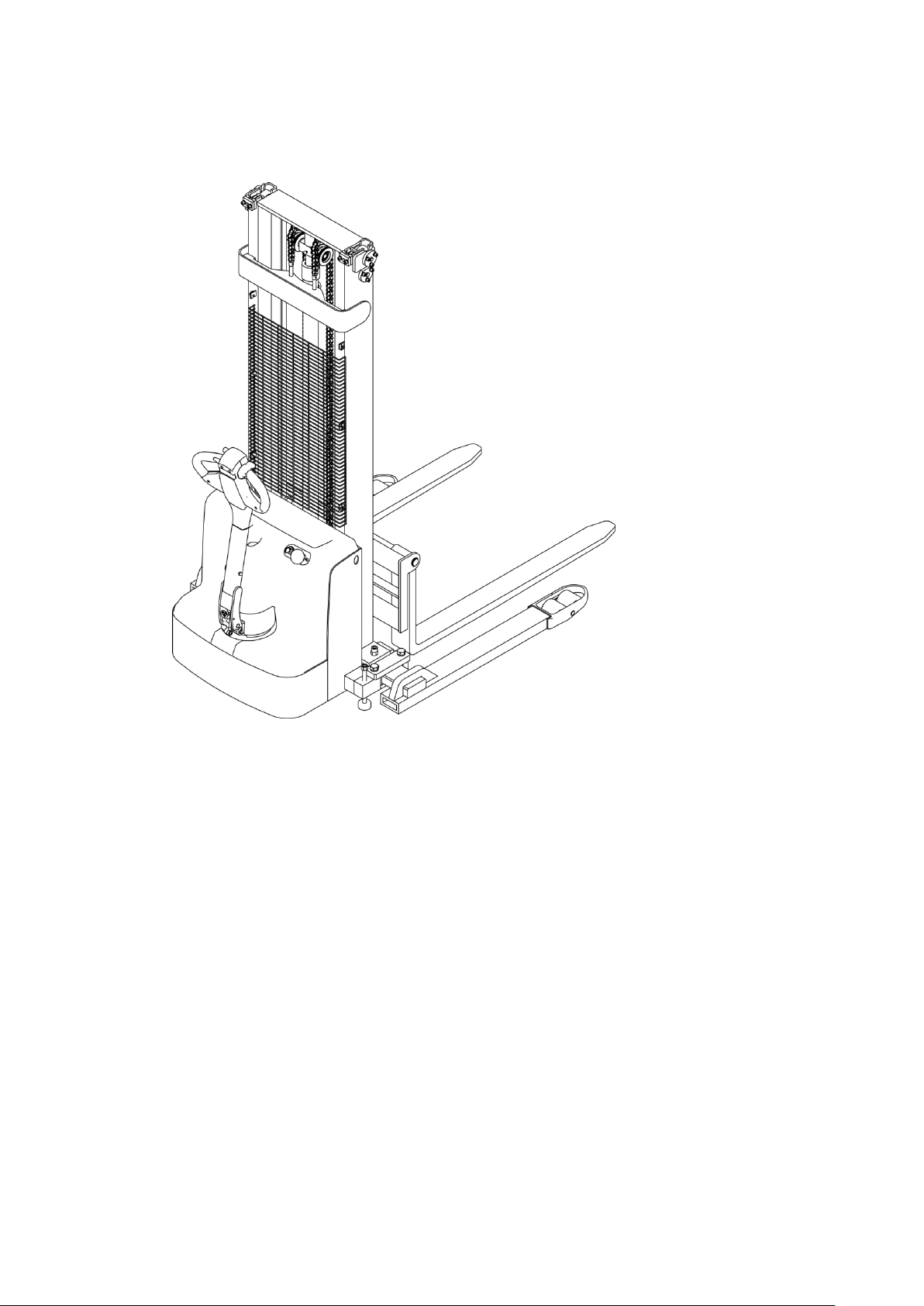
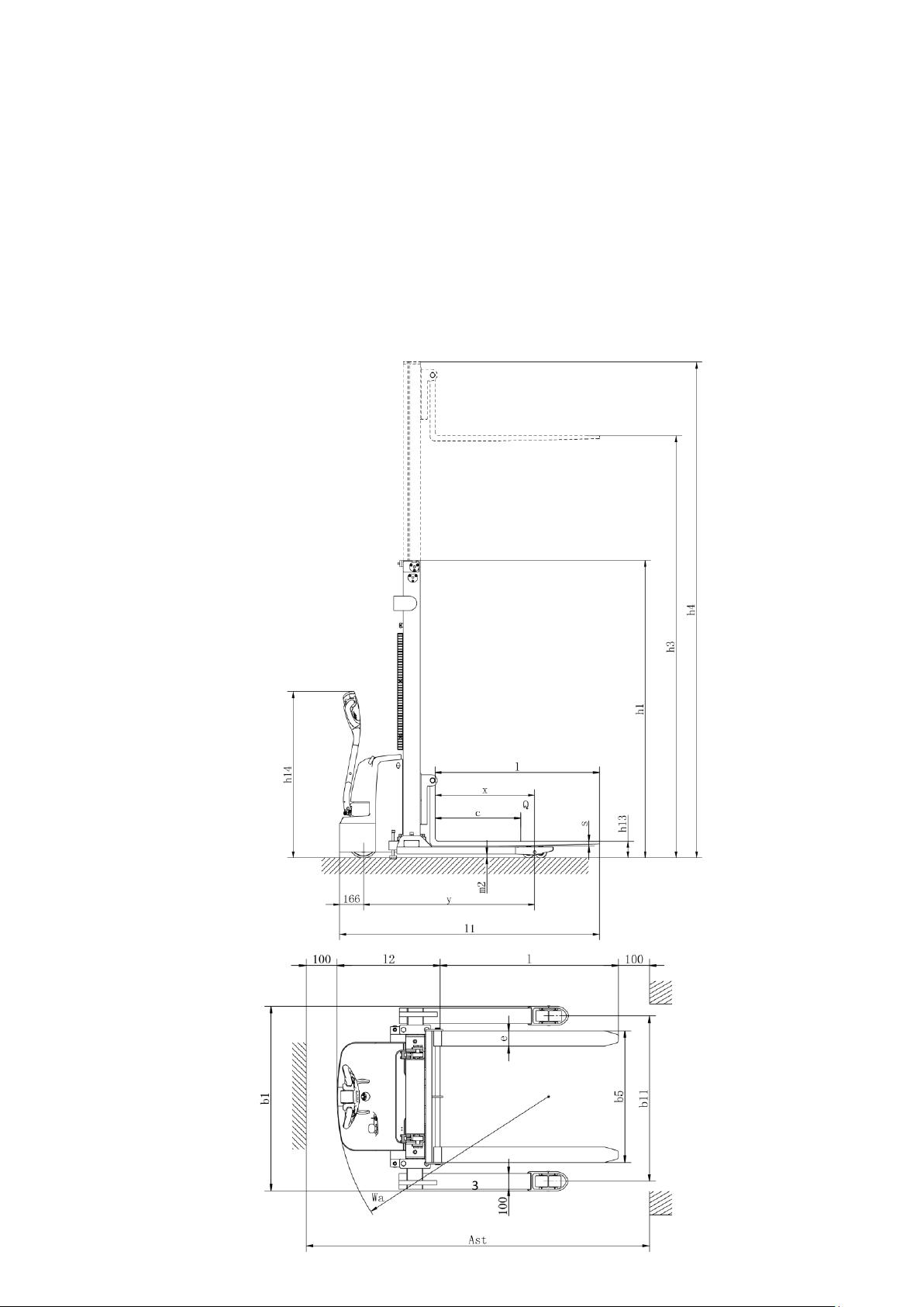
3.Introduce of the product .............................................................................................. 3
3.1Product overview ............................................................................................................. 3
3.2Model parameters............................................................................................................. 3
4.Operating principle........................................................................................................5
5. Operating principle .......................................................................................................6
5.1Running system.................................................................................................................. 6
5.2 Steering system................................................................................................................. 6
5.3 Brake structure and brake schematic diagram. ................................................... 6
5.4 Operating System............................................................................................................. 8
5.5 Electric System.................................................................................................................. 8
5.6 Hydraulic principle.......................................................................................................... 8
6. Electrical schematic diagram.....................................................................................9
7. Hydraulic Scheme ....................................................................................................... 10
8.Operating Instruction................................................................................................. 11
8.1 Start, run and parking: .................................................................................................11
8.2The using of emergency power safety switch ......................................................11
8.3 The use of Horn and reversing Horn ......................................................................12
8.4 Battery capacity indicator...........................................................................................12
8.5Operation............................................................................................................................12
9.Maintenance and care instructions ....................................................................... 13
W1 = Every 50 work hours, but at least once a week..............................................14
10.Safety Caution ............................................................................................................. 21
10.1 General rule ...................................................................................................................21
10.2 Storage and transportation......................................................................................21
10.3 Check before using......................................................................................................22
10.4Safety operation regulation......................................................................................22
11.Service Manual ........................................................................................................... 26
12.After Sales Service..................................................................................................... 28

1
1.The General Introduction
EB13E &EB13E-138 Electric stacker ,the stacker adopts advanced
structure such as wide-field lifting system and new DC controller, and is
equipped with high-quality motor, traction battery and high-power pumping
station motor. Then it has the characteristics of superior performance,
convenient operation, wide field of view, flexible steering, reliable braking, good
power, low noise, no pollution, and beautiful appearance.
The device is suitable for Stacking & Handling cargo on firm ,flat floors
The service environment:
a. Altitude does not exceed 1200m.
b. Indoor room temperature at +5℃to +40℃.
c. When environment temperature at +40℃,the relative humidity can’t over
50%,at low temperature ,allow bigger relative humidity
d. Firm, Flat ground 。

2
e. It’s forbidden to use this car in corrosive environment such as flammable
and explosive or acid base
2. Proper use
Please using the electric Stacker according to this specification.
This is a walkie type electric stacker with autonomous control , lifting and
lowering is controlled by the handle button.
Improper use can cause personal injury or machine damage. Operators or
operating companies need to ensure proper using,
The Truck needs to be used on a firm ,flat ,intact surface and suitable surface;
the truck is designed for indoor use at room temperature from+5°C to +40°C
Use under light load without using permanent barriers or pits ,it is
forbidden to operate on the slops .During Operation ,The goods must be placed
approximately at the center of the truck’s load center
Lifting or Carrying people is strictly prohibited ,if carried goods .The goods
must fall on the lifting point 。
It is prohibited to use this truck on lifting or loading ramps.
The rated capacity is marked on the capacity label or nameplate. And the
operator must pay attention to the warming signs and safety instructions.
Operating lighting must be at lest 50LUX
Modification
Any modification that may affect the truck rated capacity, stability, or safety
operations must be approved in advance by the Truck’s original manufacturer or
Its authorized Manufacturer or its successor. This includes the effects of changes
such as Braking ,steering ,Visibility, and the addition of removable accessories.
After the manufacturer or its successor approves the modification or change ,The
capacity name plate ,Label, identification marks, operation and maintenance
manual must be changed accordingly
Truck damage caused by not following Instruction will lose its warranty.

3
3.Introduce of the product
3.1Product overview .
This specification is for EB13E & EB13E-138 Walkie Electric stacker(follow
as truck).
The type is“EB13E &EB13E-138 load capacity is 2800lbs” meet the
requirement of JB/T8452-1996《Battery forklift model establishment method》,
3.2Model parameters

4
Mode
EB13E
EB138-138
Drive type
Electric
Electric
Type of operation
Walkie type
Walkie type
Load Capacity
Q (lbs)
2800
2800
Load Centre
c (Inch)
23.6
23.6
Distance between fork backrest and front
wheel
x (Inch)
27.48
27.48
Wheelbase
y (Inch)
47.32
47.32
Service Weight(with battery)
Lbs
1430
1470
Tire material
PU
PU
Driving wheel size
Φ×w(Inch)
Φ8.27×2.76
Φ8.27×2.76
Bearing wheel size
Φ×w(Inch)
Φ3.15×2.76
Φ3.15×2.76
No of Driving wheel,/Bearing
wheel(X=Driving wheel
1x+1/04
1x+1/04
Rear wheelbase
b11 (Inch)
40.32-56.06
40.32-56.06
Lowered mast height
h1 (Inch)
81.89
91.73
Free lift height
h2 (Inch)
0
0
Lift height
h3 (Inch)
118.11
137.8
Extended mast height
h4 (Inch)
139.72
159.41
The height of handle in the operation
position
h14 (Inch)
26.77/45.87
26.77/45.87
Lowered fork height
h13 (Inch)
2.56
2.56
Overall Length
l1(Inch)
71.58
71.58
Body Length
l2 (Inch)
26.3
26.3
Overall Width
b1/ b2(Inch)
45.2-60.95
45.2-60.95
Fork Size
s/e/l (Inch)
1.39/3.94/45.3
1.39/3.94/45.3
Fork Width
b5 (Inch)
8.27-33.47
8.27-33.47
Ground clearance under mast
m2(Inch)
1.02
1.02
Aisle width for pallets 1000*1200
crossways
Ast (Inch)
88.19
88.19
Aisle width for pallets 1000*1200
lengthways
Ast (Inch)
87.01
87.01
Turing Radius
Wa (Inch)
53.94
53.94
Driving Speed,load/unload
(km/h)
4.0/4.2
4.0/4.2
Lifting Speed load/unload
(mm/s)
92/136
92/136
Lowered Speed load/unload
(mm/s)
112/98
112/98
Maximum gradeability load/unload
(%)
6./8
6./8
Brake Type
Electromagnetic
brake
Electromagnetic
brake
Drive Motor
(kW)
0.75
0.75
Lift Motor
(kW)
2.2
2.2
Battery,according to DIN 43531/35/36
A,B,C,no
no
no
Battery voltage/rate capacity
(V/Ah)
2×12/100
2×12/100
Battery Weight(±5%)
(Lbs)
2×59.4
2×59.4
Type of drive control
DC
DC
Noise level
(dB(A))
69
69
Steering type
Mechanical
Mechanical

5
4.Operating principle
The Truck with battery as power producer and controlled by electrical and
hydraulic, trucks can do some actions like walking, turning, pallet forklift, etc.
Operating mechanism diagram:
1.Up/Down Button 2.Driving Knob 3.Emergency stop switch
4.Horn Button 5.Electricity meter

6
5. Operating principle
5.1Running system
Stacker use battery as the power source through controlling DC motor on the
driving wheel to fulfill the function of walking, DC motor convert the high-speed
low torque to low speed high torque through gearbox, being implemented by
driving wheel. The speed of walking is controlled by accelerator .
In general, every 1000 hours change the lubricating oil in the gearbox.
During usage, if any noise coming from gearbox, please stop the stacker and
check, to judge whether bearing or gear have some problem.
5.2 Steering system
The steering of the stacker is driven by the operating handle through the
handlebar to drive the motor for steering.
5.3 Brake structure and brake schematic diagram.
Braking performance depends on road conditions and vehicle load conditions.
5.3.1The brake function can be activated by the following ways:
⚫Turn the travel switch (2) to "0" position or release the switch to make truck
brake until it stops.
⚫With the driving switch (2) moving directly from one driving direction to the
opposite direction, the vehicle regenerates the brake until it begins to move
in the opposite direction.
⚫The handle moves up and down to the braking area (' B ') and the truck
brakes. If the handle is released, the handle automatically moves to the upper
braking area (' B ') and the truck stops until it stops.
Emergency Reverse button (3) can prevent the operator will be squeezed, when
trucks are driven towards (' Fw) encounters an obstacle, body touch belly to slow
down or start to switch truck (' Bw) driven a short distance, then stop. If the
handle is in the operating area and the truck is not moving, please consider that
this is still working.

7
5.3.2Braking operation principle:
As follow picture:The brake constitute by magnetic yoke 6 ,magnet exciting
coil,7 , the spring 2, the brake disc 5,the armature 1, the gear sleeve 4, the
mounting screw 3,And so on .The brake is mounted on the end cap of the motor and
the mounting screw is adjusted to the specified air gap value.
When magnet exciting coil 7for brake on power,The coil generates a
magnetic field to to attract the armature 1 to the yoke assembly 6, and the
armature 1 is disengaged (released) from the brake disc 5.At this time, the motor
drive shaft is normally started and operated with the brake disc 5.When the
magnet exciting coil 7 is de-energized, the magnetic flux disappears, the armature
1 is released, and the spring 2 is pressed against the armature 1, and the friction
plate on the brake disc is pressed to generate frictional force for braking
purposes.
Brake schematic

8
5.4 Operating System
The main working body of a moving truck is a cargo fork, which relies on a fork
to carry the pallet or cargo for transport and short distance transportation. The
expansion of the cylinder is realized by the control of the operating handle, and
the pressure oil is provided by the pumping station.
A descending valve is installed in the circuit of the lifting cylinder to slow down
the speed at which the fork falls, and the safety drop effect is achieved
5.5 Electric System
The electrical system includes walking and operation control. The truck use DC
electric control assembly.
The meter has a battery indicator. When the battery power is too low, the
electric meter will cut off the starting control line of the oil pump motor. The
moving truck can only walk without lifting the fork, and the stacker should be
charged immediately.
The motor of oil pump is the DC motor for 5 minutes, so the pump motor is not
suitable for long running. That is, the lifting movement should have time interval,
can not continuously carry on, otherwise would make the motor heating, even
burn.
Special note: when the truck is used for a long time, the starter of the oil pump
motor may fail, and it can't be broken after being sucked or closed. The latter is
not throw control handle, the oil pump motor is kept in the rotation, should
immediately stop at this moment, to cut off the power supply (unplug battery
plug-in), make the oil pump motor stop running, and promptly replace the
starter.
5.6 Hydraulic principle
The oil pump motor drives the gear pump to provide hydraulic power, lifting oil
cylinder is responsible of fork’s lifting and lowering, The control of the lift oil
road is controlled by the buttons on the operating handle, The lifting action is
controlled by a single action oil circuit on the valve block. This model of the
hydraulic system pressure can only be adjusted on the valve block, has been
debugging good, before they go out after they leave the our company after-sales

9
personnel or professional maintenance personnel are strictly forbidden to adjust
themselves, so as to avoid safety accident.
6. Electrical schematic diagram

10
7. Hydraulic Scheme

11
8.Operating Instruction
Before operation, please familiarize yourself with the functions of the switches
and buttons on the dashboard.
8.1 Start, run and parking:
○
1 Insert the key into the key switch, turn to the right, the emergency power
safety switch clockwise reset, gently open the control circuit.
○
2 The fork rises from the ground about 10 cm.
○
3 Slowly turn on the travel switch until the required speed.
○
4 In the process of operation, forklift exception occurs fault, need to quickly
cut off power supply, please press the red emergency power switch.
○
5 When the forklift is turning, you should reduce the speed and, if possible,
try not to make sharp turns.
○
6 Forklift truck carrying gradeability is 10%, so the uphill slope need to
understand the situation, when climbing the forklift must accelerator pedal
pressed down as far as possible, the maximum climbing force can be achieved.
○
7 When the stacker stops , Lowered the fork to the lowest position, press
the safety switch, and pull out the key.
8.2The using of emergency power safety switch
If the forklift is out of control during driving, or if it is smoked or burnt
during use, please press the emergency switch on the forklift seat cover and the
power will be cut off. Find out the cause and clear the fault before you can open it.
The method of opening is as follows: the emergency power-off safety switch is
rotated in the direction indicated by the arrow above the button, and the opening
is completed.

12
The button of the emergency power off switch is a plastic piece. When
pressing down or rotating up, do not use excessive force to avoid damage to the
switch.
8.3 The use of Horn and reversing Horn
For the safety of driving, vehicle equipped with Horn .To remind others
when driving, press the horn button in the middle of operating handle and the
horn will ring to warn pedestrians.
8.4 Battery capacity indicator
The battery capacity of the forklift truck on the dashboard has capacity
display function.
8.5Operation
(1)How to carry goods
Will truck slowly drive to the front of the need to carry items, insert the
pallet fork and move forward slowly, when the goods completely inserted into
the goods after parking, control handle upgrade button, the heavy lifting to a
certain height, back slowly, don't touch the adjacent goods, when the weight
zone is put out the goods, and then walk handling.
(2)How to place the goods
When moving the goods close to the area of the goods, it will slow down.
When the moving truck is in a straight line with the goods, then the moving truck
will slowly move forward to the loading area to stop. Slowly press the down
button, and once the load is held, the fork will be lowered to the hollow position.
When the fork is pulled out of the weight, the back position will be confirmed
without any obstacle. Wait for the fork to leave the weight completely before
carrying on a round of handling.

13
9.Maintenance and care instructions
The spare parts of the truck are not allowed to change without permission. All
parts supplied by the original manufacturer are subject to strict quality
inspection. To ensure the safety and reliability of the vehicle, please use the
original parts. Replacement parts, including all oils, must be collected and
processed in accordance with local environmental and health laws and
regulations.
9.1 Repair and Maintenance
Maintenance technician: The maintenance and service should only be
performed by special personnel trained by the manufacturer. After the
technician sent by after-sales department of the manufacturer completed
maintenance and servicing work, they should sign on the service log.
Cleaning Operation: Flammable liquid can not be used for cleaning the stacker.
Before cleaning, take safety precautions to prevent electric sparks (e.g. sparks
caused by short circuit). When operating the accumulator, connectors on it must
be disconnected. Use soft air suction or compressed air, non-conductive and
anti-static brushes to clean electric and electronic components.
Operation of Electric System: Operation on the electric system should only be
performed by specially trained personnel. Before performing any operation on
the electric system, precautions must be made to prevent electric shock. When
operating the accumulator, connectors on it must be disconnected.
Installation: When repairing or replacing hydraulic components, electric and
electronic components, make sure to install them back to their original positions.
Wheels: Quality of the wheels has significant effect on stability and driving
performance of the truck. Modification on wheels can be performed only with
the approval from the manufacturer. When replacing wheels, ensure that the
truck is levelled as delivery state(wheels must be replaced in pairs, i.e. replace
right wheel together with left one).
Lifting chain and rollers: Chain and rollers will be worn quickly without good
lubrication. Perform periodic lubrication according to following maintenance
table. Shorten the lubrication period under adverse operation conditions (such
as in dusty and hot environment).

14
Lifting the chain and rollers: If there is no good lubrication, the chains and
rollers will wear out quickly. It must be periodically lubricated according to the
requirements of the following maintenance table. In harsh working conditions
(such as dust, high temperature), the lubrication cycle should be shortened.
Hydraulic oil pipe: The oil pipe must be changed every 6 years. When change
the hydraulic assembled parts, the oil pipe should be also changed.
9.2 Routine Maintenance
9.2.1 check the condition of each pole, cable and protective cover of the
accumulator.
9.2.2 check whether the battery box is secure.
9.2.3 check whether the vehicle is oiled.
9.2.4 check the situation of fork, oil pipe and horn.
9.2.5 check the braking condition.
9.2.6 check the wear condition of driving wheel, load wheel and so on.
9.3 Professional Maintenance Manual
It is very important for safe operation of the truck to perform overall professional
maintenance. Failure in performing maintenance according to specified interval may
cause malfunction of the truck, and potential risk to human and equipment.
Maintenance periods listed in this manual apply to single shift a day under normal
operation conditions. If using in dusty environment, the ambient temperature varies
remarkably or in multi-shift situation, the maintenance period has to be shortened.
Maintain the truck according to following maintenance list. Maintenance periods are
as follows:
W1 = Every 50 work hours, but at least once a week.
M3 = Every 250 work hours, but at least once every three months
M6 = Every 500 work hours, but at least once every six months
M12 = Every 2000 work hours, but at least once every 12 months
Additional operations should be performed in trial run period:
(In initial 50 –100 working hours or after two months)

15
—Check the nuts on the wheels and tighten them if necessary.
—Check the hydraulic components for leakage and tighten them if necessary.
—Replace the hydraulic filter.

16
Time interval(Month)●
W
A
B
C
Brake
1.1
Check the air gap of the electromagnetic brake
●
Electrical
system
2.1
Check the operation switch to show the function of the
device and components
●
2.2
Check alarm system and safety device
●
2.3
Check the cable for damage and the terminal is secure
●
2.4
Check the function of the micro switch setting
●
2.5
Check controller and EPS controller
●
2.6
Cable and motor fixing
●
Power
supply
3.1
By observing the battery
●
3.2
Visual inspection of battery charging plug
●
3.3
Check if the connection of the battery cable is tight, and if
necessary, apply the electrode with grease.
●
Driving
system
4.1
Check the gearbox for abnormal noise
●
4.2
Check the running mechanism and grease, check the reset
function of the operating handle
●
4.3
Check the drive wheel and bearing wheels for wear and
damage
●
4.4
Check wheel bearings and fixing conditions
●
Whole
frame
5.1
Check if the frame is damaged
●
5.2
Check if the sign is complete
●
5.3
Check the fixing of the mast
●
Hydraulic
movement
6.1
Check the function of the hydraulic system
●
6.2
Check hoses, pipes and connections for tightness, sealing and
damage
●
6.3
Check the cylinder and piston for damage, sealing and fixing
●
6.4
Check the load chain settings and re-tension if necessary
●
6.5
Visually inspect the mast rollers and check the wear on the
roller faces
●
6.6
Check the forks and load handlers for wear and loss
●
6.7
Check the tank for oil level
●
6.8
Update hydraulic oil
●
Maintain list
This manual suits for next models
1
Table of contents
Other EKKO Forklift manuals

EKKO
EKKO EK20R User manual

EKKO
EKKO EK18RF User manual

EKKO
EKKO Walkie EB16EA User manual

EKKO
EKKO EK20LI Series User manual

EKKO
EKKO ES40E Operating manual

EKKO
EKKO EK50LP User manual

EKKO
EKKO EK18A-189LI Service manual

EKKO
EKKO EPE20LI Series User manual

EKKO
EKKO EB20E User manual

EKKO
EKKO EK18RR User manual
Popular Forklift manuals by other brands

Hyster
Hyster D117 Service & repair manual

Presto Lifts
Presto Lifts Power Stak PPS3000-125AS Installation, operation and service manual

Noblelift
Noblelift PSE22 SL Service maintenance manual

B3C
B3C TRANSERENITE ARX user manual

Still
Still EXD 20 Original instructions

Pfaff
Pfaff HV 1008 operating instructions