EKKO EK20LI Series User manual

The Specification
EK20LI/EK22LI Series Electric Forklifts
Note Please read this manual before using!
Note Please do not use it before completing the installation!

Introduction
To meet the needs of the national environmental protection request to reduce
industrial pollution and improve productivity, we designed and produced a new series
of EK20Li/EK22Li type counterbalanced forklift based on absorption of the
advantages of domestic & overseas electric forklift. They are especially suitable for
cargo loading and unloading, handling, stacking, etc for food, bank, light textile,
station, port, logistics and other enterprises. And it can be applied widely if inter-grate
with different fixture
The electric forklift adopts wild field lifting system, EPS system, new AC
controller and open type lamp holder. It is equipped with high-quality motors, battery,
and high-power pumping stations. Therefore, it is convenient for operation with good
view, flexible steering, reliable braking, good power, low noise, no pollution, and
attractive appearance.
This manual describes the technical parameters of the counterbalanced electric
forklift, working principle and operation, maintenance, and other aspects. It can help
operators use the counterbalanced electric forklift to its maximum capabilities.
It is hoped that operator strictly abide the regulations and the precautions in this
manual when using the machine. Carefully use them so that your forklift can be in the
best working condition for long period of time to maximize its effectiveness and
create better economic benefits.

The Statement
Our production model EK20Li/EK22Li type 4500/5000lbs counterbalanced
electric forklifts is a special motor vehicle used in factory, tourist attractions,
amusement places which is specified by “special equipment safety supervision
regulations”.

Contents
1.General Introduction........................................................................................1
2.Proper use..........................................................................................................3
3.Introduction of the product .............................................................................4
4.The Schematic diagram of Operating Mechanism........................................7
5. Structure ,Principle and Adjustment of main parts of forklift ...................8
6.Electrical schematic........................................................................................25
7.Hydraulic schematic .......................................................................................26
8.Operating Specification..................................................................................27
9.Maintenance and Service Manual.................................................................30
10.Safety caution................................................................................................37
11.Service Manual..............................................................................................40
11.1Hand and foot brake common faults and troubleshooting ...........................................40
11.2steering system common faults and troubleshooting...................................................41
11.3lifting system common faults and troubleshooting......................................................42
11.4Electrical system common faults and troubleshooting.................................................43
11.5Gearbox common faults and troubleshooting..............................................................43
11.6Multi valve common faults and troubleshootin............................................................44
11.7Gear pump common faults and troubleshooting..........................................................46
11.8 Other common faults and troubleshooting..................................................................47
12.After-sales service .........................................................................................48

1
1.General Introduction
EK20Li/EK22Li type 4 wheel Counterbalanced Electric Forklift adapts battery
as the power source, uses the AC motor as the power to drive the device through the
gear transmission. The lifting and tilting of the fork are driven by the DC motor and
Hydraulic drive to push the cylinder to lift the cargo. Because the device is using
Power to travelling & lift, Forward and back tilting and side shift therefore, it is low
effort, high efficiency, stable cargo operation, simple operation, safe and reliable low
noise, and no pollution.
The biggest advantage for 4 wheel counterbalanced electric forklift is that it
adopts optimized design, wide-view mast. The mast and rubber tube pulley block are
more compact. Excellent view for the operator, the size of the fork frame is increased,
and the field of vision is wide with a large arc roof guard. The best angle of the grid is
to increase the driver’s upper view. The right-hand control handle fully reflects
ergonomics, improves the comfort of handling, and reduces the labor intensity of the
operator.

2
The device is suitable for Stacking & Handling cargo on firm, flat floors
The service environment:
a. Altitude does not exceed 47inch.
b. Indoor room temperature at +5℃ to +40℃.
c. When environment temperature at +40℃, the relative humidity can’t over
50%, at low temperature, allow bigger relative humidity
d. Firm, flat ground.
e. It is forbidden to use this car in corrosive environment such as flammable and
explosive or acid base.

3
2.Proper use
Please use the Counterbalanced electric forklift according to this specification.
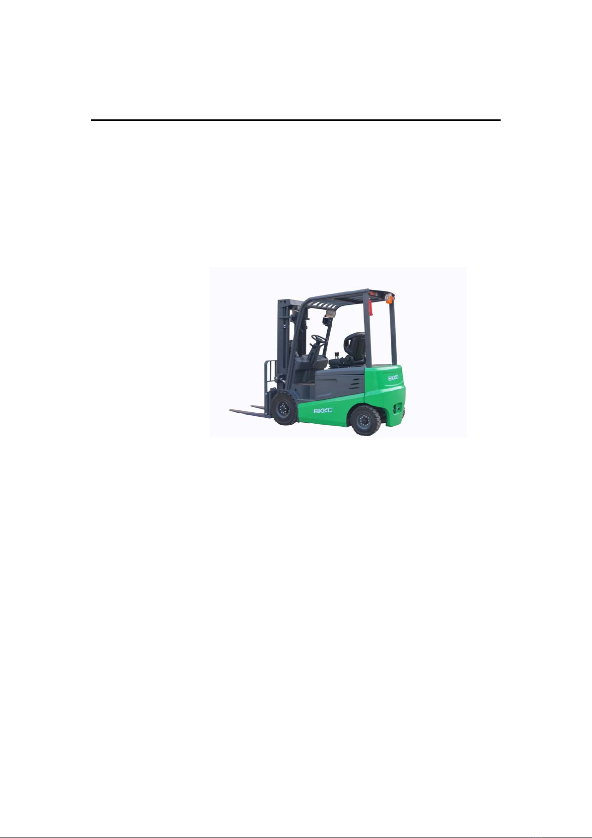
The Forklift described in this manual is a self-controlled series of
Counterbalanced Electric forklift. With Multi-way valve control forklift lifting,
Forward & backward tilting, side shifting etc. function.
Improper use can cause personal injury or machine damage. Operators or
operating companies need to ensure proper using, make sure that the truck is operated
only by personnel who are trained and authorized to use the truck.
The Truck needs to be used on a firm, flat, intact surface, and suitable surface;
The truck is designed for indoor use at room temperature from+5°C to +40°C
Use under light load without using permanent barriers or pits, it is forbidden to
operate on the slope. During Operation, the goods must be placed approximately at
the center of the truck’s load center
Lifting or Carrying people is strictly prohibited, if carried goods. The goods must
fall on the lifting point 。
It is prohibited to use this truck on lifting or loading ramps。
The rated capacity is marked on the capacity label or nameplate. And the
operator must pay attention to the warning signs and safety instructions
Operating lighting must be at lest 50LUX
Any modification that may affect the truck rated capacity, stability, or safety
operations must be approved in advance by the Truck’s original manufacturer or Its
authorized Manufacturer or its successor. This includes the effects of changes such
as Braking, steering, Visibility, and any additional or removable accessories.
Modification
After the manufacturer or its successor approves the modification or change, The
capacity name plate, Label, identification marks, operation and maintenance manual
must be changed accordingly
Truck damage caused by not following Instruction will lose its warranty

4
3.Introduction of the product
3.1Model overview
This manual is a collection of EK20Li/EK22Li type 4500/5000lbs
counterbalanced Electric forklift (Hereinafter referred to as Forklift)
3.2Product Schematic diagram & Parameter

5
Manufacturer EKKO EKKO EKKO EKKO
Model EK20-189LI EK20-216LI EK22-189LI EK22-216LI
Power unit Electric Electric Electric Electric
Operation Tower Rack Tower Rack Tower Rack Tower Rack
Rated traction weight Q (lbs.) 4500 4500 5000 5000
Load center c (Inch) 19.68 19.68 19.68 19.68
Axle center to fork face x (Inch) 18.9 18.9 18.9 18.9
Wheelbase y (Inch) 59.84 59.84 59.84 59.84
Service weight with battery lbs. 8560 8780 9065 9285
Wheels type Solid tire Solid tire Solid tire Solid tire
Driving wheel size 6.5-10-10PR 6.5-10-10PR 6.5-10-10PR 6.5-10-10PR
Bearing wheel size 5.0-8-10PR 5.0-8-10PR 5.0-8-10PR 5.0-8-10PR
Wheels, number front/rear
(x = driven) 2×/2 2×/2 2×/2 2×/2
Track width b10
(Inch) 35.43 35.43 35.43 35.43
Track width b11
(Inch) 36.53 36.53 36.53 36.53
Mast/fork carriage tilt,
forward/backward a/b (°) 6/6 6/6 6/6 6/6
Height of mast, lowered h1
(Inch) 83.94 93.11 83.94 93.11
Free lift h2
(Inch) 43.39 52.55 43.39 52.55
Lift
h3
(Inch) 189.00 216.00 189.00 216.00
Height of mast, extended
h4
(Inch) 232.09 259.64 232.09 259.64
Height of overhead guard
(cabin)
h6
(Inch)
84.25 84.25 84.25 84.25
Height of seat/stand-on
platform h7
(Inch) 43.31 43.31 43.31 43.31
Towing coupling height
h
10
(Inch) 14.57 14.57 14.57 14.57
Overall length l1
(Inch) 132.28 132.28 132.28 132.28
Length to fork face l2
(Inch) 90.16 90.16 90.16 90.16

6
Overall width
b
1
/ b
2
(Inch) 42.12/42.91 42.12/42.91 42.12/42.91 42.12/42.91
Fork dimensions s/e/l
(Inch)
1.57/4.72/42.12 1.57/4.72/42.12 1.57/4.72/42.12 1.57/4.72/42.12
Width of fork carriage
b3
(Inch) 34.25 34.2519 34.25 34.2519
Min. Ground clearance
m
2
(Inch) 3.15 3.1496 3.15 3.1496
Aisle width with pallet
1000 x 1200 across forks Ast
(Inch) 156.30 156.2989 156.30 156.2989
Aisle width with pallet 800
x 1200 along forks Ast
(Inch) 161.42 161.417 161.42 161.417
Min. Turning radius
Wa
(Inch) 86.02 86.02345 86.02 86.02345
Travel speed,
laden/unladen
(km/h) 13/11 13/11 13/11 13/11
Lifting speed, with/without
load (mm/s) 240/320 240/320 240/320 240/320
Lowering speed,
with/without load (mm/s) 360/320 360/320 360/320 360/320
Climbing ability,
with/without load (%) 12/15 12/15 12/15 12/15
Service brake Hydraulic Hydraulic Hydraulic Hydraulic
Drive motor, 60-minute
rating (kW) 7.5 7.5 7.5 7.5
Lift motor rating at S3
15% (kW) 7.7 7.7 7.7 7.7
Battery according to DIN
43531/35/36 A, B, C, no no no no no
Battery voltage/rated
capacity (V/Ah)
48V/350
Li-battery
48V/350
Li-battery
48V/404
Li-battery
48V/404
Li-battery
Battery weight (± 5%) (kg)
Type of drive control AC Controller AC Controller AC Controller AC Controller
Noise level at operator ‘s
ear (dB(A)) ≤75 ≤75 ≤75 ≤75
Hydraulic
steering Hydraulic
steering Hydraulic
steering Hydraulic
steering

7
4.The Schematic diagram of Operating Mechanism
The Forklift uses battery as power source, uses electric and hydraulic to
travelling, & Lifting, Forward & backward tilting and steering Operating Mechanism
diagram:
1. Hand braking 2. Combination switch 3. Steering wheel
4. Lifting handle 5. tilting handle 6. Side shift handle
7. Accelerator 8. Foot brake 9. Emergency stop switch

8
5. Structure, Principle and Adjustment of main parts of forklift
5.1Drive system
5.1.1Overview
The forklift is powered by battery and use a frequency conversion system to convert
direct current into alternating current by controlling the AC motor on the driving
wheel. The AC motor converts the high speed and low torque to the low speed and
high torque through the gear reducer, And the driving wheel performs the action. The
travel speed is controlled by frequency conversion motor speed. which is controlled
by accelerator
5.1.2Reducer casing
The reducer casing is located between the transaxle and the traveling motor. The two
pairs of cylindrical helical gears reduce the rotational speed from the output shaft of
the traveling motor and increase the torque transmitted from the transmission
shaft .and then transmit this torque to the differential.
reducer
1.Reducer housing 2. Pad 3. Spring washer 4. Bolt
5. Bolt 6. Hexagonal nut 7. Flat washer 8. Spring washer
9. Retaining ring 10. Bolt 11. Flat washer 12. Spline housing
13. Adjust the gasket group 14. Mechanical transmission plate
15. Bolt 16. Spiral bevel gear 17. Round nut

9
18. Stop washers for round nuts 19. Spring washer 20. Gasket set
21. Pad set 22. bearing seat 23. Bearing 24. bushing
25. Oil seal 26. bearing 27. bearing cover 28. Head Bolt
29. Spring washer 30. O-Ring 31. Pad
5.2 Steering system
5.2.1 Overview
Steering system is composed of steering wheel. Steering shaft, Steering gear,
Steering pump and steering axle. The steering shaft is connected to the steering gear
through the universal joint, And the connecting shaft is connected to the steering
wheel through the universal joint, The steering Column can be tilted back and forth to
an appropriate position. And the steering axle is mounted on the tail stock at the rear
of frame. And there is a steering on the left and the right respectively. The steering
cylinder is pushed by the steering cylinder piston rod through the connecting rod to
deflect the steering wheel to realize steering.
5.2.2Steering axle
Steering axle is a box-shaped cross-section welded structure composed of steering
axle body, steering cylinder, connecting rod, steering joint and steering wheel. The
steering trapezoid adopts a crank slider mechanism, and the cylinder piston rod
pushes the steering joint through the connecting rod to deflect the steering wheel. then
realizing steering. The steering axle is fixed to the tail stock at the rear of the frame by
the front and rear pins through the fixing plate, that is, the vibration damping pad, so
that the axle body can swing around the pin shaft. There is on joint on the left and
right sides of the steering axle .and two tapered rollers on the rear hub. The bearing is
mounted on the joint shaft. The wheel is fixed to the hub by the rim. And the inside
bearing is provided with an oil seal to keep grease in the hub .and the steering joint

10
cavity.
1.Bolt M16×12 2.Spring washer 6 3.Tighten pin 4.Connecting rod
5.Joint Bearing 6.bushing 7.left knuckle 8.steering axle
9.Steering oil cylinder 10.Cotter pin5×50 11.Groove nut 12.Flat washer27
13.Adjustable washer 14.Bearing 15.Pin 16.Flat washer12
17.Spring washer 12 18.Bolt M12×40 19. Nut M10×1.25
20.Bolt M10×1.25×40 21.Curved neck grease nozzleM6 22.Oil seal 23.Bearing
24. O-Real 25.8×1.8 25.Steering knuckle kingpin 26.Steering knuckle adjustment washer 27.Bearing
28.Fixed pin 29.Right knuckle 30.Washer 8 31.O-Real
32. Nut M8×1.25 33.Skeleton oil seal 34.steering wheel hub 35.Bearing
36.Bolt M8×18 37.Washer 24 38. Nut M24×2 39.Cotter pin5×4 40.wheel hub cover
5.2.3 Adjustment, Maintenance essential

11
(1) As the picture shows, Grease the inner cavity of the hub, The inner and outer
bearings, and the hub cap, and apply some grease to the lip of the oil seal.
(2) Fixing the outer ring of the bearing to the hub and attaching the hub to the
steering joint shaft.
(3) Install the flat washer and tighten the castle nut with a torque of
206-235n.m(21-24kgm), loosen the slotted nut and then screw the nut back, the torque
is 9.8n.m(1kgm)
(4) Gently tap the hub with a wooden hammer and turn the hub 3-4 turns to
ensure that the hub is not loose.
(5) Tighten the Castle nut so that the slot is aligned with the opening pin hole on
the Knuckle
(6) Then tap the hub with a wooden hammer and turn hub 3-4 turns by hands to
ensure smooth rotation and measure the torque of the hub, the value is
2.94-7.8N.m(0.3-0.8kgm)
(7) When the turning torque is higher than the specified value, It can be retracted
1/6 turn, and then measure its rotational torque
Inject grease
(8) When reach the specified torque. Then lock the slot nut with a split pin.

12
5.2.4 Check after reinstallation of steering system
(1) Turn the steering wheel from side to side and see whether the forces are even,
and the rotation is steady.
(2) Check whether the oil pressure pipe is arranged correctly, and weather the
left and right steering is installed in reverse.
(3) Lift the rear wheel. slowly turn the steering wheel left and right .and repeat it
several times to remove the air from the hydraulic lines and cylinders.
5.3 Braking system and schematic diagram.
5.3.1overview
The brake mode of the forklift consists of two types: service brake and parking brake.
The service brake refers to the braking method used by the forklift during the
operation, Brake with foot brakes.
When the brake cylinder pumps the brake drum to the same force as the main
brake shoe and the auxiliary brake shoe until the upper end of the brake shoe is
pressed against the fixed pin, The brake shoe moves in the direction of the brake drum.
After the fixed pin is pressed, the frictional force between the friction lining and the
brake drum is increased. Because the main brake shoe gives the auxiliary brake shoe a
much greater pressure than the brake cylinder pressure, thereby generating a large
braking force.
The parking brake is mainly used in the parking state to prevent accidents caused
by slopes. A parking switch is mounted on the parking brake .and the control circuit is
disconnected in the parking The stop brake must be released before the forklift starts

13
to walk, and the control circuit can be connected. Parking brake has the function of
adjusting tightness.
5.3.2Brake pedal
The brake pedal portion is constructed as shown in the figure ,and the pedal converts
in the pedaling force acting on the pedal into the brake oil pressure by the push rod of
the master cylinder .
1.Brake oil cup 2. Brake pedal 3. Brake master Cylinder 4. brake
support 5. limit bolt 6. brake sensor
5.3.3 Brake master cylinder
The master cylinder includes a valve seat, a check valve, a return spring, and a
main cup, piston and auxiliary cup. The end is fixed with a retaining washer and a
retaining wire, and the outside is protected by a rubber dust cap. The master cylinder
piston is actuated by the operating brake pedal through the push rod, when the brake
pedal is depressed ,the push rod pushes the piston forward .and the brake fluid in the
pump body flows back to the oil storage tank through the oil return port until the main
the cup stops the oil return hole .After the main cup is pushed over the oil return
port .The brake fluid in the front chamber of the main pump is compressed and the
check valve is opened to flow through the brake line to the sub -Pump.in this
way ,each of the sub-pump pistons protrudes outward, so that the brake shoe friction
plate and the brake drum are in the contact with each other to achieve the effect of
deceleration of braking .At this time ,The rear chamber of the piston is replenished by
the brake fluid from the oil return port and the oil inlet port .When the brake pedal is
released ,the piston is pressed back by the return spring and the brake fluid in each
brake cylinder is also compressed by the brake shoe return spring .so that the brake
fluid returns to the original position. The brake fluid in the master cylinder flows back
to the oil storage tank through the oil return port. The pressure of the check valve is
adjusted to a certain ratio with the residual pressure in the brake line and the brake
cylinder. So that the cylinder of the pump is properly placed to prevent oil leakage
and eliminate the possible air resistance during emergency braking.

14
1.Lock nut 2. Push Rod 3. Dust cover
4.Locking wire 5. Lock washer 6. Auxiliary cup
7. piston 8. Master cup 9. Spring
10. Check valve 11. Valve seat 12. Pump body
5.3.4Brake
The brakes are double-hoof brakes mounted on both sides of the trans axle. The
brake consists of 2 sets brake shoes, brake cylinder and regulator. One end of the
brake shoe is in contact with the fixing pin .and the other end is in contact with the
adjusting device. Press the brake stop by the return spring and the compression spring
lever. In addition. the brake is equipped with stop brake mechanism and automatic
adjustment device.
1. Brake base plate assembly 2. Slack adjuster 3. Friction disc assembly 4. Elastic gasket
wire 5. Hand brake lever 6.Return Spring 7. Washer 8. Pole 9.Return Spring

15
10. Hand push Rod 11. Compressed spring 12. Adjustment Lever 13. Pressure
spring seat 14. Spring 15.Pressure spring Cover 16.Spring
17.Pressure spring seat 18.Pressure spring Lever 19.Support pin
20.Washer 21.Rubber plug 22.Brake cable assembly
23.Bolt M8×16 24.Spring Washer 8 25.Brake cylinder
26.Brake pump guard 27.Brake pump piston top rod 28.Piston
29.Cylinder Cup 30.Brake pump spring 31.Brake oil plug
32.Brake cylinder Bleed screw 33.screw protector for pump vent 34.Dust cover
5.3.5Parking brake operating device
The parking brake handle is cam type. And the brake can be adjusted by the
adjuster at the end of the brake handle.
Braking force adjustment: turn the adjuster clockwise to increase the braking
force ,turn the adjuster counterclockwise to reduce the braking force, pulling
force:200 N~300N
5.3.6 Brake assembly and adjustment essentials
Decomposition, assembly, adjustment of the brake and adjustment of the brake
pedal in the dissembled state of the wheel and the hub
1、Decomposition of the brake
(1) Remove the support pin, adjustment lever, adjustment device and spring on
the auxiliary brake shoe. As figure 1
(2) Remove the shoe return spring, as figure 2
Parking brake handle

16
Figure 1 Figure 2
(3) Remove the anchor spring on the main brake show, as figure 3
(4) Remove the main brake shoe and the auxiliary brake shoe, Remove the
adjuster and adjuster spring at the same time, as figure 4
Figure 3 Figure 4
(5) Remove the brake pipe from the brake cylinder, then remove the mounting bolts of the brake cylinder and
remove the brake cylinder from the brake base.as figure 5
(6) Remove the E-shaped retaining ring for the brake cable on the brake base plate, then remove the bolts that
mount the brake base plate and remove the brake base plate from the drive axle. Figure 6
figure 5
figure 6
This manual suits for next models
5
Table of contents
Other EKKO Forklift manuals
Popular Forklift manuals by other brands

Hyster
Hyster D117 Service & repair manual

Presto Lifts
Presto Lifts Power Stak PPS3000-125AS Installation, operation and service manual

Noblelift
Noblelift PSE22 SL Service maintenance manual

B3C
B3C TRANSERENITE ARX user manual

Still
Still EXD 20 Original instructions

Pfaff
Pfaff HV 1008 operating instructions