manuals.online logo
Brands
  1. Home
  2. •
  3. Brands
  4. •
  5. emaux
  6. •
  7. Underwater Lighting
  8. •
  9. emaux EL-H200 User manual

emaux EL-H200 User manual

EL-H200
UNDERWATER LIGHT OPERATING MANUAL
Keep this manual for future reference
www.emauxgroup.com
4-14-4
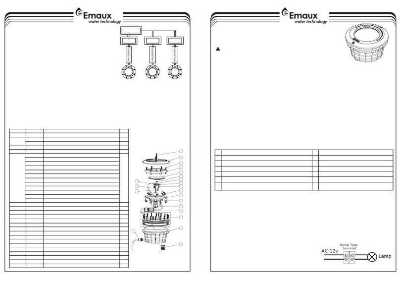
V. REPLACEMENT PARTS
13 14
Mode E: RGB Colour Sequence: Red>Green>Blue
Mode F: Four Colour Sequence: Red>Green>Blue>Purple
Auto Colour Change
1
3
5
7
9
11
2
4
6
8
10
12
White Green
Green+Blue
Red+Blue
Mode B: Green+Gradual Red
Blue
Red+Green
Mode C: Blue+Gradual Green
Mode A: Blue+ Gradual Red
Mode D: Blue+Gradual Red
Rapid Auto Colour Change
EL-H200
SAFETY WARNINGS
• Avoid direct contact with electrical power.
• Respect all regulations in effect for preventing accidents.
• All units are required to be disconnected from the main electricity before any operation of maintenance.
• Never handle with wet hands and feet.
• This unit is design for use only when fully submerged in fresh water, connecting with a safety transformer
• Never operate this Underwater Light for more than 1 minute unless it is totally submerged in water.
• Be sure power is off before installing or removing LED plate. Allow LED plate to cool before replacing.
• This product should be installed according to your local electrical installation ordinances and regulations.
o
• Maximum Water Temperature Range for light operation 0 - 30 C
A) Electrical Specification : 1) Voltage : AC12V 2) Frequency : 50/60Hz 3) Power : 20W / 35W / 50W.
B) Colour Options(For RGB version only) :
• Only qualified electrician is allowed to carry out the installation of this product.
EMLI16082533
ON/OFF Switch
Light
Transformer
Light
Transformer
Master Switch
Light
Transformer
ON/OFF Switch ON/OFF Switch
IV
1 When the light is connected to the transformer
directly, the on/off switch controls the colour
changes (Associating a light with a transformer
and an on/off switch is recommended; If you want
all the lights to change colour at the same time,
install a master switch, Figure 3).
2) If applicable, when the light is connected to the
transformer and the transformer to the optional
control box, the control panel on the control box
and its remote control controls the colour changes
(See the Control Box Manual for details).
. Control
)
Figure 3
www.emauxgroup.comwww.emauxgroup.com
2
3
4
5
15
16
17
1
6
7
8
9
10
11
12
13
14
Item
No.
Part No.
Description
Qty
1
03011123
M5*10 Screw for Lid
1
2
03017138
Lid for EL-H200 Lighits
1
3
03013004
Hexagonal Nut (M4)
4
4
01110028
Fastener
4
5
03011348
M4*22 Screw
4
6
04011153
Ultra-Thin 252 LED panel 20W,Warm white
1
04011151
Ultra-Thin 252 LED panel 20W,Cool white
04011152
Ultra-Thin 252 LED panel 20W,RGB
04011150
Ultra-Thin 252 LED panel 20W,Single Blue
04011107
Ultra-Thin 441 LED panel 35W,Warm white
04011105
Ultra-Thin 441 LED panel 35W,Cool white
04011106
Ultra-Thin 441 LED panel 35W,RGB
04011104
Ultra-Thin 441 LED panel 35W,Single Blue
04011181
Ultra-Thin 531 LED panel 50W,Warm white
04011179
Ultra-Thin 531 LED panel 50W,Cool white
04011180
Ultra-Thin 531 LED panel 50W,RGB
04011178
Ultra-Thin 531 LED panel 50W,Single Blue
7
03011360
M3*5 round head screw
2
8
02021085
Silica gel ring
1
9
01050105
Bottom cover
1
10
03011361
M4*10 round head self-tapping screw
5
11
02010285
NBR ring
2
12
04013004
2
2*1.5mm *2.5m(D8) Cable
1
13
03012125
M4*10 flat head self-tapping screw
2
14
01050100
Cable Clip
3
15
89041604
Wate Joint Fittings for Cable
1
16
01171101
EL-H200 Lighits niche
1
17
01171106
Joint for Wine & Pipe
1
4-34-2
A) The electrician must complete preparatory steps before light fixture is installed;see Figure 1.
I. Installing light fixture during new pool construction.
48"
min.
9.84”
16”
4” min.
Leakage protection
switch
Hard pipe
The of junction box or transformer
at least 8 inches from the surface
bottom
Mounting connector
The of the underwater light
at least 18 inches from the surface
top
The top screw installed
in 6 o’clock direction
Concrete wall have a concave
space for covered with plaster
The cable enlaced about 4
inches behind the lights
1 Ensure that the pool meets the requirements of the current National Electrical Code and all
local codes and ordinances. A licensed or certified electrician must install the electrical
system to meet or exceed those requirements before the underwater light is installed. Some of
the requirements of the National Electrical Code which the Pool's electrical system must meet
are as follows.
a) The lighting circuit must have a Ground Fault Circuit Interrupter (GFCI), and must have an
appropriately rated circuit breaker.
b) The Junction Box (or, for 12 volt models, the low voltage transformer) must be located at least
20CM above water level, at least 10CM above ground level, and at least 120CM from the
edge of the pool; see Figure 1.
c) The light fixture and all metal items within 152CM of the pool must be properly electrically
bonded.
d) The wet niche must be properly installed so that the top edge of the underwater light's lens is
at least 45.5 below the surface of the water in the pool; see Figure 1.
e) The wet niche must be properly electrically bonded and grounded via the No.8 AWG ground
connector located at the rear of the niche; see Figure 1.
NOTE: The pool or spa electrical system can be verified with a pool and Spa Electrical
Qualification Test kit. The electrical system inspection using this kit must be performed by
trained and certified personnel.
2 To be certain that pool's electrical system meets all applicable requirements, the electrician
should also consult the local building department.
3
)
)
) Terminal blocks must meet the IEC60988-2-1 standard having
the rated connecting capacity of 4,0mm2 use of screw-
type terminal at least 25A rated current ,mounted on junction
boxes inside. See Figure2-1
1 Feed cord through conduit to Junction Box, leaving at least 120CM of cord at the light
fixture to coil
)
B) Steps to perform after the electrical system requirements are met.
Figure 1
The light housing installed within the walls
(to ensure that the wall is not higher than
the mounting plate surface),Install wiring
duct
Aimed at the hole of the mounting
plate,install the locating pin
Tightening coverthe screw on the
Figure 2
III.
• Do not leave the lights directly under sunlight. Fill the pool with fresh water as soon as
possible after the lights are installed.
• Before switching on the lights, check whether the lights are fully submerged underwater
and the circuit boxes are running properly.
• This unit does not need any kind of maintenance. If it is not working properly, please
contact EMAUX authorized dealer where you purchase the unit from.
• Warranty will be voided if the Emaux Underwater Light was dismantled by unauthorized
personnel.
Maintenance of the Lights
• Do not leave the lights “on” above water for longer than 1 minute.
I . I
I nstallation
WARNING
Never operate this Underwater Light for more than 10 seconds unless it is totally
submerged in water. Without total submersion, the light assembly will get extremely
hot, which may result in serious injury to pool users, installers, or bystanders, or in
damage to property.
Use only the special stainless steel pilot screw provided with Underwater Light. Failure
to use the screw provided could create an electrical hazard which could result in
death or serious injury to pool users, installers or others due to electrical shock.
around the light; see Figure 1. This 120CM of cord around the light allows the light to be
serviced after the pool is filled with water.
2 Cut the cord at the Junction BOX, leaving at least 15CM of cord to make connections.
3 Strip 15CM of the outer cord jacket to expose the three insulated wires. Be careful not to
damage the insulation on the three (3) inner wires.
4 Connect all three (3) wires to the corresponding circuit wires in the Junction Box, and secure
the Junction Box cover in place.
5 Replace the light assembly into niche and tighten special pilot screw.
6 Fill the pool until the underwater light is completely submerged in water before operating the
light for more than 10 seconds. Turn on main switch or circuit breaker, as well as the switch
which operates the underwater light itself, to check for proper operation.
)
)
)
)
)
Figure 2-1
www.emauxgroup.comwww.emauxgroup.com
Other emaux Underwater Lighting manuals

emaux UL-P100 Series Manual

emaux

emaux UL-P100 Series Manual

emaux LED-P100 series Manual

emaux

emaux LED-P100 series Manual

emaux LED-P10 User manual

emaux

emaux LED-P10 User manual

emaux EL-NP300 Series User manual

emaux

emaux EL-NP300 Series User manual

emaux P50 Instructions for use

emaux

emaux P50 Instructions for use

emaux ElumenX Series User manual

emaux

emaux ElumenX Series User manual

emaux NP300 Series User manual

emaux

emaux NP300 Series User manual

emaux UL-TP100 Series Manual

emaux

emaux UL-TP100 Series Manual

emaux P50 User manual

emaux

emaux P50 User manual

emaux LED-TP100 Series Manual

emaux

emaux LED-TP100 Series Manual

emaux E-Lumen X User manual

emaux

emaux E-Lumen X User manual

emaux E-Lumen Compact User manual

emaux

emaux E-Lumen Compact User manual

emaux E-Lumen X Series User manual

emaux

emaux E-Lumen X Series User manual

emaux UL-P300 Series User manual

emaux

emaux UL-P300 Series User manual

emaux UNDERWATER LIGHT Series User manual

emaux

emaux UNDERWATER LIGHT Series User manual

emaux Arr30 User manual

emaux

emaux Arr30 User manual

emaux UL-CP100 User manual

emaux

emaux UL-CP100 User manual

emaux EL-S100S User manual

emaux

emaux EL-S100S User manual

emaux GL10 User manual

emaux

emaux GL10 User manual

emaux E-Lumen-252 User manual

emaux

emaux E-Lumen-252 User manual

emaux NP300 Series User manual

emaux

emaux NP300 Series User manual

emaux NP300 Series User manual

emaux

emaux NP300 Series User manual

Popular Underwater Lighting manuals by other brands

Sea & Sea YS-D1 instruction manual

Sea & Sea

Sea & Sea YS-D1 instruction manual

Sea & Sea YS-D3 instruction manual

Sea & Sea

Sea & Sea YS-D3 instruction manual

Northern Diver Varilux 3500 user manual

Northern Diver

Northern Diver Varilux 3500 user manual

O'Ryan Industries PoolStar SP2527C instruction manual

O'Ryan Industries

O'Ryan Industries PoolStar SP2527C instruction manual

Oase LunAqua Power LED Series operating instructions

Oase

Oase LunAqua Power LED Series operating instructions

Light & Motion SunRay-S Pro Lighting System owner's manual

Light & Motion

Light & Motion SunRay-S Pro Lighting System owner's manual

Aqualuma TRIM TAB LIGHT Fitting instructions

Aqualuma

Aqualuma TRIM TAB LIGHT Fitting instructions

Larson Electronics LEDEUL4 instruction manual

Larson Electronics

Larson Electronics LEDEUL4 instruction manual

LIGMAN BOH-60003 installation manual

LIGMAN

LIGMAN BOH-60003 installation manual

Ikelite DS230 manual

Ikelite

Ikelite DS230 manual

METALSUB KL 1255 quick start guide

METALSUB

METALSUB KL 1255 quick start guide

Underwater Lights USA Sea Vision SV16 Maintenance and care

Underwater Lights USA

Underwater Lights USA Sea Vision SV16 Maintenance and care

Nanight Cave 2 user manual

Nanight

Nanight Cave 2 user manual

Intex FL690 owner's manual

Intex

Intex FL690 owner's manual

Shadow-Caster Color-Caster SCM Series operating instructions

Shadow-Caster

Shadow-Caster Color-Caster SCM Series operating instructions

Messner UWL 1205 LED/Tec operating instructions

Messner

Messner UWL 1205 LED/Tec operating instructions

LIGMAN OR-60894 installation manual

LIGMAN

LIGMAN OR-60894 installation manual

Poolexa Jandy Pro Series installation manual

Poolexa

Poolexa Jandy Pro Series installation manual

manuals.online logo
manuals.online logoBrands
  • About & Mission
  • Contact us
  • Privacy Policy
  • Terms and Conditions

Copyright 2025 Manuals.Online. All Rights Reserved.