3-4
C) Winterizing: Light should be left in place for winterization.
2-4
120CM MIN.
WATER LEVEL
6.6CM
29.6CM
RIGID CONDUIT
TO POWER SOURCE;
FEED PARAFFIN
CONCRETE MUST BE CUT BACK
AROUND NICHE TO ALLOW FOR
A COMPACT PLASTER SEAL
45CM MIN. FROM WATER LINE
TO TOP OF LENS
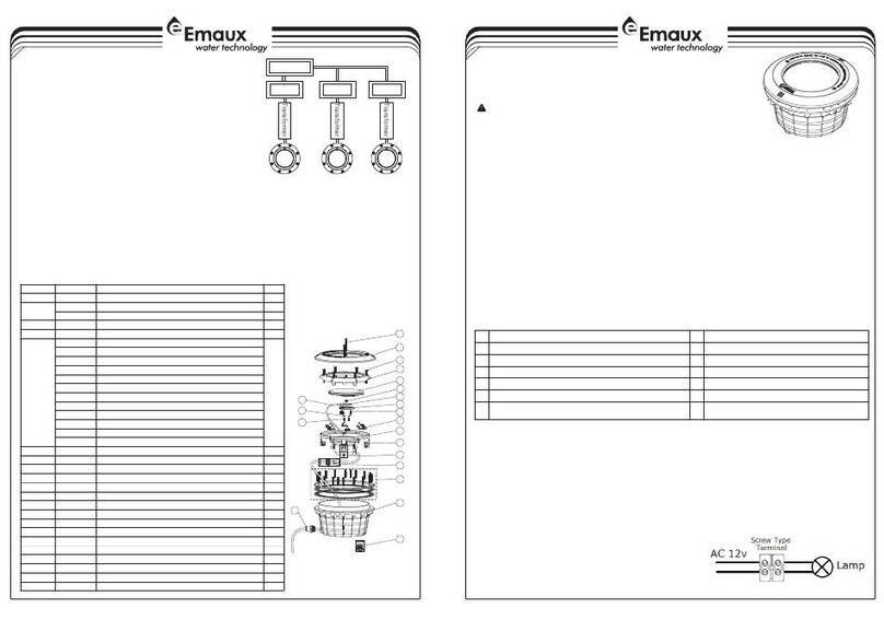
A) Preparatory steps which must be completed by the electrician before light
is installed, see Figure 1.
INSTALLATION
Figure 1.
2 Connect conduit to midst of Mounting Spacer (left of Bracket),see Figure 2.
3) If pool surface is to be plastered, you must allow proper concrete cutback for
plaster thickne-ss. Finish concrete surface must be flush with Mounting Spacer.
CAUTION: Finish area surrou-nding Mounting Spacer MUST be flat and flush with the
face of Mounting Spacer, this ensures a snug fit between light and wall, see Figure 3.
4) After pool surface is finished, trim the Conduit.
5) Wrap a length of the cord up to a maximum of 2.4mt long on the back of the light
assembly. This extra cord allows you to bring the light out of the pool for relamping and
servicing.
6) Connect cord electrical wires at Junction box, through Conduit, be careful not to pull
the 75mm-80mm of slack cord at the light through the con-duit when connecting the
wires.
7) Connect all wires to the corresponding circuit wires in the junction box and feed paraffin.
8) Secure the junction box cover in place.
9) Before operating the light for more than 10 sec-onds fill pool until the Underwater Light is
comp-letely submerged in water. To check for proper operation turn on main switch
or circuit breaker as well as the switch that operates the Underwater Light itself.
10) Rotating Locking System ensures light is sec-ured to bracket, see Figure 4.(Figure 5.)
)
B) Perform the following steps after the electrical system requirements are met.
1 Locate position on a vertical wall where light is to
plate must be 45 cm below normal water level, see Figure 1.
) Be installed. The edge of the face
FOR FIBREGLASS POOL, PRE-FAB
MODULAR POOL AND VINYL LINER POOL
Figure 3.
Figure 2.
DO NOT MOUNT ON:
REVERSE RADIUS
SURFACE
IRREGULAR OR
UNEVEN SURFACES
DO MOUNT ON:
FLAT
SURFACE
WALLS WITH NO TIGHTER
THAN 6 FT. RADIUS AS
VIEWED FROM TOP
MOUNTING BRACKET
CONDUIT
LIGHT
Figure 4.
O P E N
P O S I T I O N
L O C K
P O S I T I O N
F O R C O N CR E T E P O O L
O P E N
P O S I T I O N
L O C K
P O S I T I O N
Figure 5.
F O R F I B RE G L A S S P O O L,
P R E - F AB M O D U L A R P O OL
A N D V I N YL L I N E R P O O L
1) Ensure that the electrical system and its wiring for the pool conform to the requirements
of your govenment or your local authorities. The installa-tion of the Underwater Light
should only be per-formed by a licensed electrician.
a) The junction box, or the low voltage transfor-mer for 12 volt Underwater Light model is
to be located at least 120cm from the edge of the pool, see Figure 1.
b) The light fixture and all metal parts that are within 240cm of the pool must be properly
protected with non-ductile materials and that the connections must be waterproof.
c) The mounting bracket must be properly instal-led so that the top edge of the
Underwater Light lens is at least 45cm below the surface of the water in the pool, see
Figure 1.
2) Consult the local Government Building Departm-ent to be certain that the pool's
electrical system meets all applicable requirements.


