manuals.online logo
Brands
  1. Home
  2. •
  3. Brands
  4. •
  5. ENFORCER
  6. •
  7. Security System
  8. •
  9. ENFORCER SD-7113-GSP User manual

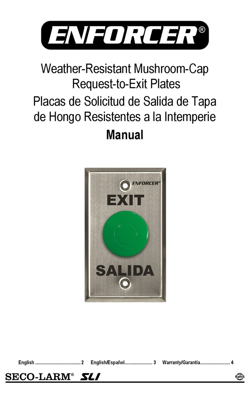
ENFORCER SD-7113-GSP User manual

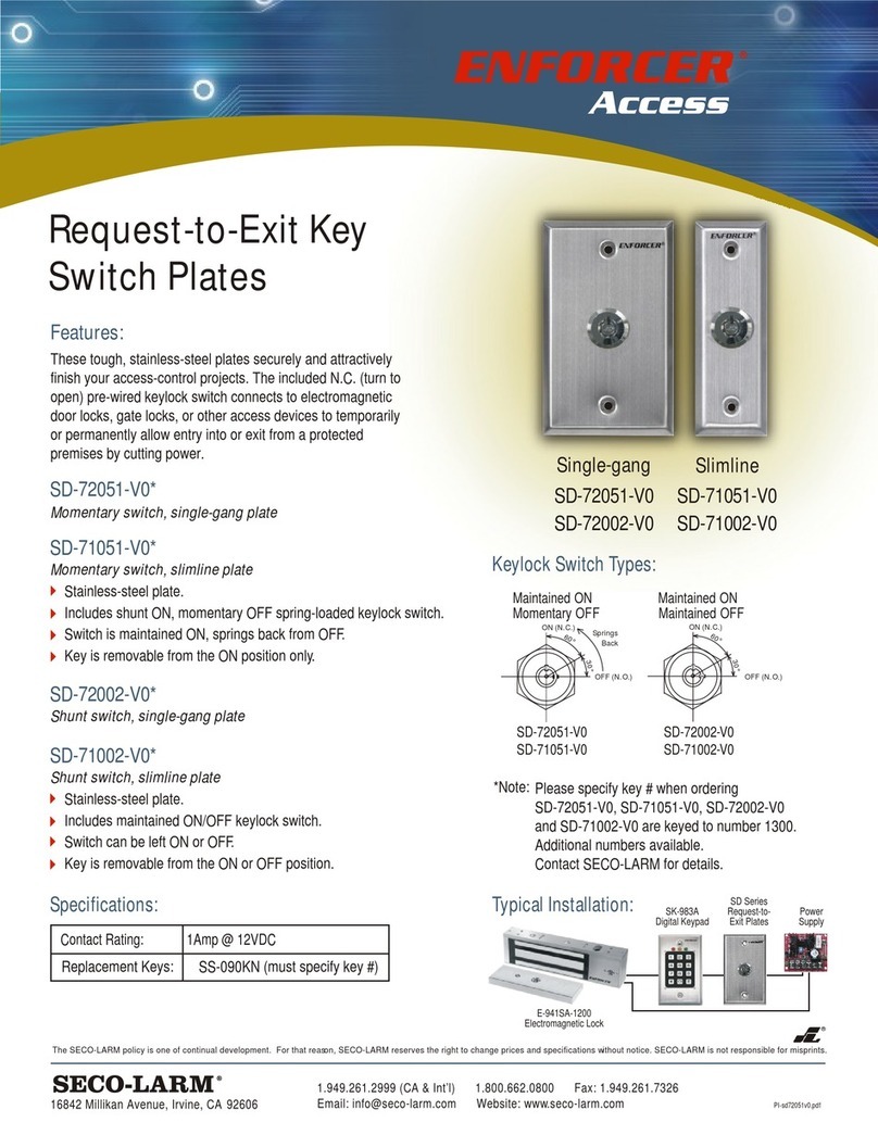
Request-to-Exit Plate
with Pneumatic Timer
Installation Manual
SD-7213-GSP shown
Pneumatic
Timer
No
Power
Required
5024193
Conforms to
UL294
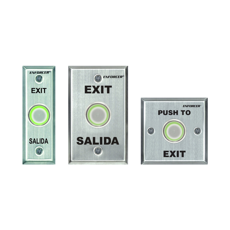
Model Faceplate Message Pushbutton
SD-7113-GSP Slimline plate xit / Salida Green mushroom
SD-7113-RSP Slimline plate xit / Salida Red mushroom
SD-71 3-GSP Slimline plate Push to xit Green mushroom
SD-7213-GSP Single-gang plate xit / Salida Green mushroom
SD-7213-RSP Single-gang plate xit / Salida Red mushroom
SD-72 3-RSP Single-gang plate Push to xit Large red mushroom
The NFORC R SD-7xx3-xSP series Request-to- xit Plates with Pneumatic Timer are ideal when
providing power to a timer is inconvenient, hazardous, or not conforming with local ordinances and
codes. Adjusting the time is easy via a timing screw and can be performed on the spot without tools.
•Conforms to NFPA 101 Fire Codes for non-electrical breaking of contact
•Functions entirely without electricity
•xcellent for installations where supplying additional timer power is inconvenient
•Reliable US-made pneumatic components
•Stainless steel single-gang faceplate
•nglish and Spanish printed on the faceplate (except SD-7183-GSP, SD-7283-RSP)
•Timer adjustable for 1~60 seconds
Request-to-Exit Plate with Pneumatic Timer
2 SECO-LARM U.S.A., Inc.
Parts List
1x
Request
-
to
-
exit plate
2x
Faceplate
screws
1x
Manual
Specifications
Model SD-7113-GSP SD-7113-RSP SD-71 3-GSP SD-7213-GSP SD-7213-RSP SD-72 3-RSP
Faceplate Slimline, brushed stainless steel Single-gang, brushed stainless steel
Mushroom
cap button
Size Standard Large
Color Green Red Green Red
Timer Pneumatic: 1~60 seconds*
Switching capacity 5A@125VAC
Wiring Red 2x N.C. #18 AWG 9" (230mm) for fail-safe
White 2x N.O. #18 AWG 9" (230mm) for fail-secure
Destructive attack level Level I
Line security Level I
Endurance level Level I
Standby power Level I
Operating temperature 32°~131° F (0°~55° C)
Dimensions 1
1
/
2
"x4
1
/
2
"x3
1
/
2
" (38x115x88 mm) 2
3
/
4
"x4
1
/
2
"x3
1
/
2
" (70x115x88 mm)
* Note: Time is precise to within ±10% for constant temperature and may vary according to environmental factors.
Overview
31/2"
(88mm)
11/2"
(38
mm)
11/2"
(38
mm)
41/2"
115 mm)
SD-7113-xSP SD-7183-GSP
23/4"
(70mm)
23/4"
(70mm)
PUSH
TO EXIT
SD-7213-xSP
SD
-
7283
-
R
SP
PUSH
TO
EXIT
Request-to-Exit Plate with Pneumatic Timer
SECO-LARM U.S.A., Inc. 3
Installation
1. Find a suitable location for the pneumatic request-to-exit plate.
2. The pneumatic request-to-exit plate can be either surface mounted or flush mounted.
3. Wire the request-to-exit plate as described below in Wiring.
4. Adjust the timer as described below in Adjusting the Timer.
5. Test the function of the exit plate and timer, as well as the timer delay.
Wiring
1. For N.C. operation (fail-safe), connect the red wires to the electronic lock or other device.
2. For N.O. operation (fail-secure), connect the white wires to the electronic lock or other device.
NOTE: Use only low-voltage, power-limited/Class 2 power supply and low-voltage field wiring not
to exceed 98.5ft (30m).
Adjusting the Timer
1. Locate the timing screw as shown in the figure to the right.
2. Gently rotate the timing screw to:
a. To increase the delay, turn the screw clockwise.
b. To decrease the delay, turn the screw counterclockwise.
NOTE: Do not overtighten or over-loosen the timing screw. If the
screw becomes very loose, retighten it until it feels secure.
3. The minimum delay time is approximately 1 second, and the
maximum delay time is approximately 60 seconds. Use a stopwatch
to adjust the time to suit the application.
Sample Applications
Installation with a Maglock and Access Control System
(SD-7213-xSP Shown)
For N.C. (fail-safe) operation,
connect the red wires.
S CO-LARM Series
lectromagnetic Lock
Access Control
Power Supply
Use NFORC R Request-to- xit
Plates with Pneumatic Timer anywhere
zero-spark switching is required.
(–)
(
+
)
Timing Screw
Timer Assembly
Request-to-Exit Plate with Pneumatic Timer
IMPORTANT WARNING
:
Incorrect mounting which leads to exposure to rain or moisture inside the enclosure could cause a dangerous electric shock, d
amage the
device, and void the warranty. Users and installers are responsible for ensuring that this product is properly installed and sealed
IMPORTANT:
Users and installers of this product are responsible for ensuring that the installation and configuration of this product com
plies with all national, state,
and local laws and codes. S CO-LARM will not be held responsible for the use of this product in violation of any current laws or codes.
California Proposition 65 Warning:
These products may contain chemicals which are known to the State of California to cause cancer and birth defects or other
reproductive harm. For more information, go to www.P65Warnings.ca.gov.
WARRANTY:
This S CO
-
LARM product is warranted against defects in material and workmanship while used in normal service for
one
(
1
)
year from the date of sale
to the original customer. S CO-LARM’s obligation is limited to the repair or replacement of any defective part if the unit is returned, transportation prepa
id, to
S CO-LARM. This Warranty is void if damage is caused by or attri
buted to acts of God, physical or electrical misuse or abuse, neglect, repair or alteration, improper
or abnormal usage, or faulty installation, or if for any other reason S CO-LARM determines that such equipment is not operating properly as a result of ca
uses other
than defects in material and workmanship. The sole obligation of S CO-LARM and the
purchaser’s exclusive remedy, shall be limited to the replacement or repair
only, at S CO-LARM’s option. In no event shall S CO-LARM be liable for any special, co
llateral, incidental, or consequential personal or property damage of any
kind to the purchaser or anyone else.
NOTICE:
The S CO
-
LARM policy is one of continual development and improvement. For that reason,
S CO
-
LARM
reserves the right to change specifica
tions without
notice. S CO-LARM is also not responsible for misprints. All trademarks are the property of S CO-LARM U.S.A., Inc. or their respective owners. Copyright © 2023
S CO-LARM U.S.A., Inc. All rights reserved.
Sample Applications (Continued)
Installation with a Maglock and an Access Control Keypad
Access Control
Power Supply
Digital Keypad
(outside the
protected area)
Request-To- xit
Plate
(inside the
protected area)
NFORC R
lectromagnetic Lock
Tamper
O/P (N.C.)
(
+
)
(
–
)
(
–
) (+)
12VDC Battery
(optional)
EXIT
SALIDA
SECO-LARM ®U.S.A., Inc.
16842 Millikan Avenue, Irvine, CA 92606
Website:
www.seco
-
larm.com
Phone: (949) 261-2999 | (800) 662-0800 mail: sales@seco-larm.com
PITSW1
Order Part# 763-172-5%
MI_SD-7xx3-xSP_220909.docx
This manual suits for next models

5

Other ENFORCER Security System manuals

ENFORCER Enforcer 32-WE User manual

ENFORCER

ENFORCER Enforcer 32-WE User manual

ENFORCER E-931CS22RFCQ User manual

ENFORCER

ENFORCER E-931CS22RFCQ User manual

ENFORCER E-921CPQ User manual

ENFORCER

ENFORCER E-921CPQ User manual

ENFORCER E-921APQ User manual

ENFORCER

ENFORCER E-921APQ User manual

ENFORCER E-931CS22RFCQ User manual

ENFORCER

ENFORCER E-931CS22RFCQ User manual

ENFORCER E-931CS22RFCQ User manual

ENFORCER

ENFORCER E-931CS22RFCQ User manual

ENFORCER Enforcer SD-927PKC-NEQ User manual

ENFORCER

ENFORCER Enforcer SD-927PKC-NEQ User manual

ENFORCER SD-7201GC-PEQ User manual

ENFORCER

ENFORCER SD-7201GC-PEQ User manual

ENFORCER RINS1708-3 Installation and operating manual

ENFORCER

ENFORCER RINS1708-3 Installation and operating manual

ENFORCER E-931CS22RRC User manual

ENFORCER

ENFORCER E-931CS22RRC User manual

ENFORCER SD-7157-SSTQ User manual

ENFORCER

ENFORCER SD-7157-SSTQ User manual

ENFORCER Enforcer Access SD-71002-V0 User manual

ENFORCER

ENFORCER Enforcer Access SD-71002-V0 User manual

ENFORCER SECO0LARM SLI RM-R100-TBQ User manual

ENFORCER

ENFORCER SECO0LARM SLI RM-R100-TBQ User manual

Popular Security System manuals by other brands

Watchguard DVR4EONPACK manual

Watchguard

Watchguard DVR4EONPACK manual

New Deal Protect Live quick guide

New Deal

New Deal Protect Live quick guide

Uniden G7404D1 owner's manual

Uniden

Uniden G7404D1 owner's manual

DSC POWER 608 instruction manual

DSC

DSC POWER 608 instruction manual

Stahl 8491/2 Series operating instructions

Stahl

Stahl 8491/2 Series operating instructions

GE Security Pro 1000 user guide

GE

GE Security Pro 1000 user guide

Defiant DF-5718-RS-D Use and care guide

Defiant

Defiant DF-5718-RS-D Use and care guide

AJAX KeyPad user manual

AJAX

AJAX KeyPad user manual

Apollo XP95 IS installation guide

Apollo

Apollo XP95 IS installation guide

fadini MIRI 4 manual

fadini

fadini MIRI 4 manual

jeiko JKAL37BR manual

jeiko

jeiko JKAL37BR manual

Climax CTC-1052 user manual

Climax

Climax CTC-1052 user manual

Europlex SigNET 200 user guide

Europlex

Europlex SigNET 200 user guide

Spyclops SPY-NVR4720W user manual

Spyclops

Spyclops SPY-NVR4720W user manual

American Dynamics RABW4QUAD Installation and setup guide

American Dynamics

American Dynamics RABW4QUAD Installation and setup guide

CrimeStopper SP-102 owner's manual

CrimeStopper

CrimeStopper SP-102 owner's manual

Bradley S19-320 Installation

Bradley

Bradley S19-320 Installation

System Sensor SpectrAlert S1224MCW Installation and maintenance instructions

System Sensor

System Sensor SpectrAlert S1224MCW Installation and maintenance instructions

manuals.online logo
manuals.online logoBrands
  • About & Mission
  • Contact us
  • Privacy Policy
  • Terms and Conditions

Copyright 2025 Manuals.Online. All Rights Reserved.