manuals.online logo
Brands
  1. Home
  2. •
  3. Brands
  4. •
  5. Epilog Laser
  6. •
  7. Engraver
  8. •
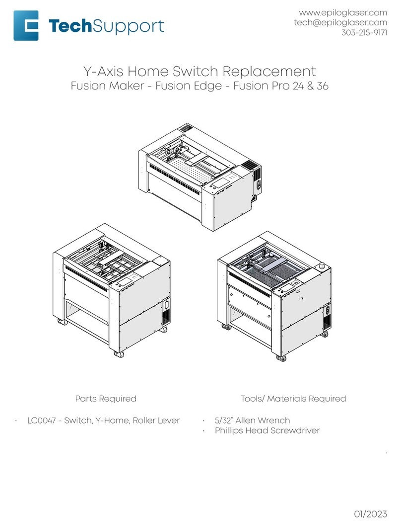
  9. Epilog Laser Fusion Pro 32 User manual

Epilog Laser Fusion Pro 32 User manual

www.epiloglaser.com
tech@epiloglaser.com
303-215-9171
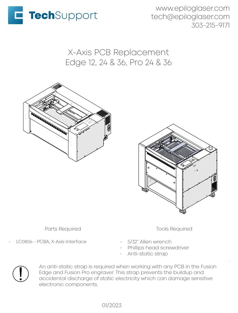
Carriage Camera Replacement
Fusion Pro 24 & 36
Parts Required Tools Required
• LC0240 - Assy, Camera, X-Axis • 5/32” Allen wrench
• Phillips head screwdriver
.
An anti-static strap is required when working with any PCB in the Fusion Pro
engraver. This strap prevents the buildup and accidental discharge of static
electricity which can damage sensitive electronic components.
!
01/2023
17000 Carriage Camera Replacement
2
Using the Anti-Static
Strap
An anti-static strap is required when
working with any PCB in the Fusion Pro
engraver. This strap prevents the buildup
and accidental discharge of static
electricity which can damage sensitive
electronic components.
1. Remove the anti-static strap from
packaging.
2. Place the strap around your wrist
and adjust the strap to be tight but
comfortable.
3. Aer sizing the strap, ensure that the
adjustment clamp is in the closed
position:
Clamp Closed
Clamp Open
There is a small metal plate on the inside
of the anti-static strap. Ensure that this
metal plate is in contact with your skin.
4. The image below shows the correct
way to wear the anti-static strap:
5. Once the strap is secure to your
wrist, attach the alligator clip to a
bare metal suace in the engraver.
Common locations include screw
through holes, engraver side panel
tabs, or the chassis.
17000 Carriage Camera Replacement
3
6. The preferred location to attach the
alligator clip is the chassis bolt that
connects to the ground from the
regenerative clamp, located behind
the right panel of the engraver:
Carriage Camera
Replacement
Carriage Camera Removal
1. Turn o the engraver.
2. Disconnect the engraver from power
source.
3. Remove the right panel of the
engraver:
4. Open the top door of the engraver:
17000 Carriage Camera Replacement
4
5. Manually move the x-axis assembly to
the middle of the engraver:
6. Disconnect the autofocus switch
electrical harness:
7. Disconnect the air assist tubing from
the camera bridge:
8. Disconnect the electrical harness from
the carriage camera PCB:
9. Loosen and remove the two (2) Phillips
screws that secure the cable track to
the carriage assembly:
BACK SIDE OF X-AXIS ASSEMBLY
17000 Carriage Camera Replacement
5
10. Loosen and remove the two (2) Phillips
screws that secure the camera bridge
to the carriage assembly:
11. Move the camera bridge to the right:
12. Place the anti-static strap around your
wrist and attach the clamp to a bare
metal suace in the machine.
!
13. Hold the carriage camera housing to
ensure it does not fall and become
damaged. Loosen and remove the
three (3) Phillips screws that secure the
carriage camera board housing to the
camera bridge:
14. Loosen and remove the seven
(7) Phillips screws that secure the
carriage camera board to the
carriage camera housing:
17000 Carriage Camera Replacement
6
15. Remove the carriage camera board
from the carriage camera housing:
Carriage Camera Installation
1. Place the anti-static strap around your
wrist and attach the clamp to a bare
metal suace in the machine.
!
2. Place the carriage camera board in
the carriage camera housing:
3. Install and tighten the seven (7) Phillips
screws that secure the carriage
camera board to the carriage camera
housing:
17000 Carriage Camera Replacement
7
4. Place the carriage camera housing in
the camera bridge. Install and tighten
the three (3) Phillips screws that secure
it:
5. Move the camera bridge to the le:
6. Install and tighten the two (2) Phillips
screws that secure the camera bridge
to the carriage assembly:
7. Install and tighten the two (2) Phillips
screws that secure the cable track to
the carriage assembly:
8. Connect the air assist tubing to the
camera bridge:
9. Connect the electrical harness to the
carriage camera PCB:
BACK SIDE OF X-AXIS ASSEMBLY
17000 Carriage Camera Replacement
8
Programming the Lens Camera
Board
1. Reconnect to power and turn on the
engraver.
2. At the display panel, press the gear
icon in the upper right-hand corner of
the display to open the Settings menu:
3. Press and hold the word “Settings”
on the display to gain access to the
Advanced Settings menu:
4. Once in the Advanced Settings menu,
enter the Diagnostics menu and use
the arrow keys to scroll to the Camera
tab:
5. Press the Test & Update button and
follow the on-screen prompts to
update the carriage camera.
6. Once the update has completed, exit
the Diagnostics menu.
7. Aer replacing the carriage camera,
complete the focus calibration and
camera calibration procedures
outlined in the Fusion Pro User’s
Manual, available here:
• https://www.epiloglaser.com/assets/
downloads/manuals/fusionseries-
manual-web.pdf
if further assistance is required, please
contact Epilog Tech Support by phone at
303-215-9171, or by email at
tech@epiloglaser.com.

Other manuals for Fusion Pro 32

5

This manual suits for next models

1

Other Epilog Laser Engraver manuals

Epilog Laser Fusion User manual

Epilog Laser

Epilog Laser Fusion User manual
Epilog Laser FiberMark User manual

Epilog Laser

Epilog Laser FiberMark User manual

Epilog Laser FiberMark User manual

Epilog Laser

Epilog Laser FiberMark User manual

Epilog Laser Zing User manual

Epilog Laser

Epilog Laser Zing User manual

Epilog Laser Fusion Use and care manual

Epilog Laser

Epilog Laser Fusion Use and care manual

Epilog Laser Fusion User manual

Epilog Laser

Epilog Laser Fusion User manual

Epilog Laser Fusion User manual

Epilog Laser

Epilog Laser Fusion User manual

Epilog Laser Fusion User manual

Epilog Laser

Epilog Laser Fusion User manual

Epilog Laser FiberMark Fusion 13000 User manual

Epilog Laser

Epilog Laser FiberMark Fusion 13000 User manual

Epilog Laser FiberMark User manual

Epilog Laser

Epilog Laser FiberMark User manual

Epilog Laser Mini Series User manual

Epilog Laser

Epilog Laser Mini Series User manual

Epilog Laser Zing User manual

Epilog Laser

Epilog Laser Zing User manual

Epilog Laser MINI User manual

Epilog Laser

Epilog Laser MINI User manual

Epilog Laser Fusion User manual

Epilog Laser

Epilog Laser Fusion User manual

Epilog Laser Fusion User manual

Epilog Laser

Epilog Laser Fusion User manual

Epilog Laser MINI User manual

Epilog Laser

Epilog Laser MINI User manual

Epilog Laser Fusion Pro 32 User manual

Epilog Laser

Epilog Laser Fusion Pro 32 User manual

Epilog Laser Fusion Pro 32 User manual

Epilog Laser

Epilog Laser Fusion Pro 32 User manual

Epilog Laser Fusion Use and care manual

Epilog Laser

Epilog Laser Fusion Use and care manual

Epilog Laser LEGEND 24EX 6000 User manual

Epilog Laser

Epilog Laser LEGEND 24EX 6000 User manual

Epilog Laser Fusion User manual

Epilog Laser

Epilog Laser Fusion User manual

Epilog Laser Fusion M2 32 User manual

Epilog Laser

Epilog Laser Fusion M2 32 User manual

Epilog Laser FiberMark User manual

Epilog Laser

Epilog Laser FiberMark User manual

Epilog Laser FusionPro 16000 User manual

Epilog Laser

Epilog Laser FusionPro 16000 User manual

Popular Engraver manuals by other brands

Parkside PMGS 12 Operation and safety notes

Parkside

Parkside PMGS 12 Operation and safety notes

Parkside 75273 Operation and safety notes

Parkside

Parkside 75273 Operation and safety notes

GRAVOGRAPH L-SOLUTION 100 Ex Fibre user manual

GRAVOGRAPH

GRAVOGRAPH L-SOLUTION 100 Ex Fibre user manual

COMGROW 5W Laser Module user manual

COMGROW

COMGROW 5W Laser Module user manual

Parkside PGG 15 B1 Operation and safety notes

Parkside

Parkside PGG 15 B1 Operation and safety notes

EK-Team VE 600 operating instructions

EK-Team

EK-Team VE 600 operating instructions

NEJE 3 MAX user manual

NEJE

NEJE 3 MAX user manual

Parkside PMGS 12 A1 Operation and safety notes

Parkside

Parkside PMGS 12 A1 Operation and safety notes

Universal Laser Systems VersaLaser VL-200 Safety, installation, operation, and basic maintenance manual

Universal Laser Systems

Universal Laser Systems VersaLaser VL-200 Safety, installation, operation, and basic maintenance manual

Omtech POLAR 350 owner's manual

Omtech

Omtech POLAR 350 owner's manual

Parkside 359506 2101 Translation of the original instructions

Parkside

Parkside 359506 2101 Translation of the original instructions

G-WEIKE G1 user manual

G-WEIKE

G-WEIKE G1 user manual

ATOMSTACK A 5 Pro installation manual

ATOMSTACK

ATOMSTACK A 5 Pro installation manual

manuals.online logo
manuals.online logoBrands
  • About & Mission
  • Contact us
  • Privacy Policy
  • Terms and Conditions

Copyright 2025 Manuals.Online. All Rights Reserved.