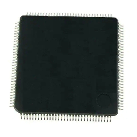
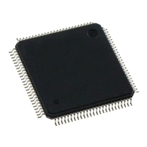
Epson S2R72V18 User manual

Rev.1.00
S2R72V18
Technical Manual

NOTICE
No part of this material may be reproduced or duplicated in any form or by any means without the written
permission of Seiko Epson. Seiko Epson reserves the right to make changes to this material without notice.
Seiko Epson does not assume any liability of any kind arising out of any inaccuracies contained in this material
or due to its application or use in any product or circuit and, further, there is no representation that this material is
applicable to products requiring high level reliability, such as, medical products. Moreover, no license to any
intellectual property rights is granted by implication or otherwise, and there is no representation or warranty that
anything made in accordance with this material will be free from any patent or copyright infringement of a third
party. This material or portions thereof may contain technology or the subject relating to strategic products
under the control of the Foreign Exchange and Foreign Trade Law of Japan and may require an export license
from the Ministry of Economy, Trade and Industry or other approval from another government agency.
All other product names mentioned herein are trademarks and/or registered trademarks of their respective
companies.
©SEIKO EPSON CORPORATION 2008, All rights reserved.

Scope
This document applies to the S2R72V18 USB 2.0 device/host controller LSI.

S2R72V18 Technical Manual (Rev.1.00) EPSON i
Table of Contents
1. Functions........................................................................................................................................... 1
1.1 USB Ports................................................................................................................................ 1
1.2 USB Device/Host Selection ..................................................................................................... 2
1.2.1 USB Device/Host Function Selection Procedure............................................................... 2
1.2.2 USB Port State Change Detection Status.......................................................................... 2
1.2.2.1 USB Port State Change Detection Status Usage Examples........................................... 2
1.2.2.1.1 Device Port Change Status..................................................................................... 2
1.2.2.1.2 Host Port Change Status ........................................................................................ 3
1.2.2.2 Signal Line Change Status Usage.................................................................................. 3
1.3 USB Device Control................................................................................................................. 6
1.3.1 Endpoints.......................................................................................................................... 6
1.3.2 Transactions...................................................................................................................... 8
1.3.2.1 SETUP Transactions .................................................................................................... 10
1.3.2.2 Bulk/Interrupt OUT Transactions .................................................................................. 11
1.3.2.3 Isochronous OUT Transactions .................................................................................... 12
1.3.2.4 Bulk/Interrupt IN Transactions ...................................................................................... 13
1.3.2.5 Isochronous IN Transaction.......................................................................................... 14
1.3.2.6 PING Transactions .......................................................................................................15
1.3.3 Control Transfers............................................................................................................. 16
1.3.3.1 Setup Stage.................................................................................................................. 17
1.3.3.2 Data Stage/Status Stage............................................................................................... 18
1.3.3.3 Automatic Address Setup Function .............................................................................. 18
1.3.3.4 Descriptor Reply Function ............................................................................................ 18
1.3.4 Bulk/Interrupt/Isochronous Transfers............................................................................... 19
1.3.5 Data Flow ........................................................................................................................ 19
1.3.5.1 OUT Transfer................................................................................................................ 19
1.3.5.2 IN Transfer.................................................................................................................... 20
1.3.6 Bulk-Only Support ........................................................................................................... 20
1.3.6.1 CBW Support............................................................................................................... 21
1.3.6.2 CSW Support............................................................................................................... 22
1.3.7 Cable Negotiation Function (Auto Negotiator) ................................................................. 23
1.3.7.1 Auto Negotiator ............................................................................................................ 24
1.3.7.1.1 DISABLE .............................................................................................................. 24
1.3.7.1.2 IDLE...................................................................................................................... 24
1.3.7.1.3 WAIT_TIM3US...................................................................................................... 24

ii EPSON S2R72V18 Technical Manual (Rev.1.00)
1.3.7.1.4 WAIT_CHIRP........................................................................................................ 25
1.3.7.1.5 WAIT_RSTEND .................................................................................................... 25
1.3.7.1.6 DET_SUSPEND ................................................................................................... 25
1.3.7.1.7 IN_SUSPEND....................................................................................................... 25
1.3.7.1.8 CHK_EVENT........................................................................................................ 26
1.3.7.1.9 WAIT_RESTORE.................................................................................................. 26
1.3.7.1.10 ERR ...................................................................................................................... 26
1.3.7.2 Operation for Individual Bus Events ............................................................................. 26
1.3.7.2.1 Suspend Detection in HS Mode............................................................................ 26
1.3.7.2.2 Suspend Detection in FS Mode ............................................................................ 28
1.3.7.2.3 Reset Detection in HS Mode ................................................................................ 30
1.3.7.2.4 Reset Detection in FS Mode................................................................................. 31
1.3.7.2.5 HS Detection Handshake..................................................................................... 32
1.3.7.2.5.1 When Connected to the FS Host Downstream Port ....................................... 33
1.3.7.2.5.2 When Connected to the HS Host Downstream Port....................................... 35
1.3.7.2.5.3 If Reset During Sleep ..................................................................................... 37
1.3.7.2.6 Resume Issue....................................................................................................... 39
1.3.7.2.7 Resume Detection ................................................................................................ 41
1.3.7.2.8 Cable Attachment ................................................................................................. 43
1.4 USB Host Control .................................................................................................................. 45
1.4.1 Channels ......................................................................................................................... 45
1.4.1.1 Channel Outline............................................................................................................ 45
1.4.1.2 Dedicated Control Channel .......................................................................................... 47
1.4.1.3 General Channels ........................................................................................................48
1.4.1.4 Channel Usage Examples............................................................................................ 50
1.4.1.4.1 With One Storage Device Connected ................................................................... 50
1.4.1.4.2 With One Communication Device Connected....................................................... 51
1.4.1.4.3 With One Human Interface Device Connected ..................................................... 52
1.4.1.4.4 With Two Storage Devices Connected Via a Hub ................................................. 53
1.4.2 Scheduling....................................................................................................................... 54
1.4.3 Transactions.................................................................................................................... 55
1.4.3.1 SETUP Transaction...................................................................................................... 56
1.4.3.2 Bulk OUTTransaction .................................................................................................. 57
1.4.3.3 Interrupt OUT Transaction............................................................................................ 59
1.4.3.4 Isochronous OUT Transaction...................................................................................... 60
1.4.3.5 Bulk IN Transaction ...................................................................................................... 61
1.4.3.6 Interrupt IN Transaction................................................................................................63
1.4.3.7 Isochronous IN Transaction.......................................................................................... 65

S2R72V18 Technical Manual (Rev.1.00) EPSON iii
1.4.3.8 PING Transaction ......................................................................................................... 67
1.4.3.9 Low-speed (LS) Transaction ........................................................................................ 69
1.4.3.10 Split Transaction ........................................................................................................... 71
1.4.4 Control Transfers............................................................................................................. 72
1.4.4.1 Setup stage .................................................................................................................. 73
1.4.4.2 Data Stage/Status Stage............................................................................................... 73
1.4.4.3 Control Transfer Support Function ............................................................................... 74
1.4.5 Bulk/Interrupt/Isochronous Transfers............................................................................... 77
1.4.6 Data Flow ........................................................................................................................ 77
1.4.6.1 OUT Transfers.............................................................................................................. 77
1.4.6.2 IN Transfers.................................................................................................................. 78
1.4.7 Zero Length Packet Automatic Issuing Function ............................................................. 79
1.4.7.1 Bulk/Interrupt OUT Transfer Zero-Length Packet Automatic Issuing Function ............. 79
1.4.8 Bulk-Only Support Function............................................................................................. 80
1.4.9 Audio Class Assist Function ............................................................................................ 85
1.4.10 Host State Management Support Function...................................................................... 86
1.4.10.1 Host State..................................................................................................................... 86
1.4.10.1.1 IDLE...................................................................................................................... 88
1.4.10.1.2 WAIT_CONNECT ................................................................................................. 89
1.4.10.1.3 DISABLED............................................................................................................ 90
1.4.10.1.4 RESET.................................................................................................................. 90
1.4.10.1.5 OPERATIONAL .................................................................................................... 92
1.4.10.1.6 SUSPEND ............................................................................................................ 92
1.4.10.1.7 RESUME .............................................................................................................. 93
1.4.10.2 Detection Functions...................................................................................................... 94
1.4.10.2.1 VBUS Error Detection........................................................................................... 94
1.4.10.2.2 Disconnect Detection............................................................................................ 96
1.4.10.2.2.1 If HS Device is Disconnected ......................................................................... 96
1.4.10.2.2.2 If FS or LS Device is Disconnected ................................................................ 97
1.4.10.2.3 Remote Wakeup Detection ................................................................................... 98
1.4.10.2.3.1 If HS Device is Connected.............................................................................. 98
1.4.10.2.3.2 If FS Device is Connected............................................................................ 100
1.4.10.2.3.3 If LS Device is Connected............................................................................ 101
1.4.10.2.4 Device Chirp Detection Function ........................................................................ 102
1.4.10.2.4.1 If a Correct Device Chirp is Detected ........................................................... 102
1.4.10.2.4.2 If an Error Device Chirp is Detected ............................................................. 104
1.4.10.2.5 Port Error Detection ............................................................................................ 105
1.4.10.3 Individual Host State Management Support Function Explanations ........................... 106

iv EPSON S2R72V18 Technical Manual (Rev.1.00)
1.4.10.3.1 GoIDLE...............................................................................................................106
1.4.10.3.2 GoWAIT_CONNECT .......................................................................................... 108
1.4.10.3.2.1 If an FS Device is Connected ....................................................................... 108
1.4.10.3.2.2 If an LS Device is Connected ....................................................................... 110
1.4.10.3.3 GoDISABLED ..................................................................................................... 112
1.4.10.3.3.1 If an HS Device is Connected....................................................................... 112
1.4.10.3.3.2 If an FS Device is Connected ....................................................................... 114
1.4.10.3.3.3 If an LS Device is Connected ....................................................................... 116
1.4.10.3.4 GoRESET........................................................................................................... 118
1.4.10.3.4.1 Resetting for HS Device ............................................................................... 118
1.4.10.3.4.2 Error Device Chirp Detection........................................................................ 121
1.4.10.3.4.2.1 If Chirp Completion Disable
(H_NegoControl_1.DisChirpFinish) Setting is 0 ....................................... 121
1.4.10.3.4.2.2 If Chirp Completion Disable
(H_NegoControl_1.DisChirpFinish) Setting is 1 ....................................... 123
1.4.10.3.4.3 Resetting for FS Device................................................................................ 126
1.4.10.3.4.4 Resetting for LS Device................................................................................ 128
1.4.10.3.5 GoOPERATIONAL.............................................................................................. 129
1.4.10.3.6 GoSUSPEND...................................................................................................... 130
1.4.10.3.6.1 If HS Device is Connected............................................................................ 130
1.4.10.3.6.2 If FS Device is Connected............................................................................ 132
1.4.10.3.6.3 If LS Device is Connected............................................................................ 134
1.4.10.3.7 GoRESUME........................................................................................................ 136
1.4.10.3.7.1 If HS Device is Connected............................................................................ 136
1.4.10.3.7.2 If FS Device is Connected............................................................................ 138
1.4.10.3.7.3 If LS Device is Connected............................................................................ 140
1.4.10.3.8 GoWAIT_CONNECTtoDIS ................................................................................. 142
1.4.10.3.9 GoWAIT_CONNECTtoOP .................................................................................. 143
1.4.10.3.9.1 If HS Device is Connected............................................................................ 143
1.4.10.3.9.2 If FS or LS Device is Connected .................................................................. 145
1.4.10.3.10 GoRESETtoOP................................................................................................... 147
1.4.10.3.10.1 If HS Device is Connected............................................................................ 147
1.4.10.3.10.2 If FS or LS Device is Connected .................................................................. 148
1.4.10.3.11 GoSUSPENDtoOP ............................................................................................. 149
1.4.10.3.12 GoRESUMEtoOP ............................................................................................... 151
1.5 Power Management Functions ............................................................................................ 152
1.5.1 SLEEP........................................................................................................................... 153
1.5.2 ACTIVE ......................................................................................................................... 153
1.6 FIFO Management .............................................................................................................. 154

S2R72V18 Technical Manual (Rev.1.00) EPSON v
1.6.1 FIFO Memory Map ........................................................................................................ 154
1.6.2 Descriptor Area.............................................................................................................. 155
1.6.2.1 Writing Data to Descriptor Area .................................................................................. 155
1.6.2.2 Executing Data Stage (IN) with Descriptor Area ......................................................... 156
1.6.3 CBW Area...................................................................................................................... 156
1.6.3.1 CBW Area (for USB device) ....................................................................................... 156
1.6.3.2 CBW Area (for USB host) ........................................................................................... 156
1.6.4 CSW Area...................................................................................................................... 157
1.6.4.1 CSW Area (for USB device) ....................................................................................... 157
1.6.4.2 CSW Area (for USB host) ........................................................................................... 157
1.6.5 FIFO Access Methods ................................................................................................... 157
1.6.5.1 RAM Access (RAM_Rd) ............................................................................................. 157
1.6.5.2 RAM Access (RAM_WrDoor) ..................................................................................... 158
1.6.5.3 FIFO Access (Register Access).................................................................................. 158
1.6.5.4 FIFO Access (DMA) ................................................................................................... 158
1.6.5.5 FIFO Access Restrictions ........................................................................................... 159
1.7 CPUIF.................................................................................................................................. 160
1.7.1 CPUIF Mode.................................................................................................................. 160
1.7.2 CPUIF Mode Setup ....................................................................................................... 161
1.7.3 Block Configuration .......................................................................................................163
1.7.3.1 REG (Registers) .........................................................................................................163
1.7.3.1.1 Synchronous Register Access (Write) ................................................................ 163
1.7.3.1.2 Synchronous Register Access (Read) ................................................................ 163
1.7.3.1.3 FIFO Access (Write) ........................................................................................... 164
1.7.3.1.4 FIFO Access (Read) ........................................................................................... 164
1.7.3.1.5 FIFO Access Fractional Number Processing ...................................................... 165
1.7.3.1.6 RAM_Rd Access................................................................................................. 168
1.7.3.1.7 Asynchronous Register Access (Writing)............................................................ 168
1.7.3.1.8 Asynchronous Register Access (Reading).......................................................... 168
1.7.3.2 DMA0/DMA1(DMA ch.0/ch.1)..................................................................................... 169
1.7.3.2.1 Basic Functions .................................................................................................. 169
1.7.3.2.2 Terminal Setup.................................................................................................... 171
1.7.3.2.3 Count Mode (Write) ............................................................................................ 171
1.7.3.2.4 Count Mode (Read) ............................................................................................ 173
1.7.3.2.5 Free-run Mode (Write) ........................................................................................ 175
1.7.3.2.6 Free-run Mode (Read) ........................................................................................ 175
1.7.3.2.7 REQ Assert Count Option (Write) ....................................................................... 176
1.7.3.2.8 REQ Assert Count Option (Read) ....................................................................... 177

vi EPSON S2R72V18 Technical Manual (Rev.1.00)
1.7.3.2.9 DMA FIFO Access Fractional Number Processing ............................................. 177
2. Register Maps ............................................................................................................................... 178
2.1 Register Configuration......................................................................................................... 178
2.2 Initial Register Map.............................................................................................................. 179
2.3 Port 0 Register Maps........................................................................................................... 180
2.3.1 Device/Host Common Register Map ............................................................................. 180
2.3.2 Device Register Map ..................................................................................................... 186
2.3.3 Host Register Map.........................................................................................................190
2.4 Port 1 Register Maps........................................................................................................... 195
2.4.1 Device/Host Common Register Map ............................................................................. 195
2.4.2 Host Register Map.........................................................................................................201
3. Register Details............................................................................................................................. 206
3.1 Device/Host Common Register Details ............................................................................... 206
3.1.1 Port0:000h / Port1:200h MainIntStat (Main Interrupt Status) ...................................... 207
3.1.2 Port0:001h / Port1:N/A USB_DeviceIntStat (USB Device Interrupt Status)................. 209
3.1.3 Port0:002h / Port1:202h USB_HostIntStat (USB Host Interrupt Status)...................... 211
3.1.4 Port0:003h / Port1:203h CPU_IntStat (CPU Interrupt Status) ..................................... 213
3.1.5 Port0:004h / Port1:204h FIFO_IntStat (FIFO Interrupt Status).................................... 214
3.1.6 Port0:006h / Port1:206h RootIntStat (Root Interrupt Status)....................................... 215
3.1.7 Port0:008h / Port1:208h MainIntEnb (Main Interrupt Enable) ..................................... 216
3.1.8 Port0:009h / Port1:N/A USB_DeviceIntEnb (Device Interrupt Enable)........................ 217
3.1.9 Port0:00Ah / Port1:20Ah USB_HostIntEnb (Host Interrupt Enable)............................ 218
3.1.10 Port0:00Bh / Port1:20Bh CPU_IntEnb
(CPU Interrupt Enable)................................... 219
3.1.11 Port0:00Ch / Port1:20Ch FIFO_IntEnb (FIFO Interrupt Enable) ................................. 220
3.1.12 Port0:010h / Port1:210h RevisionNum (Revision Number)......................................... 221
3.1.13 Port0:011h / Port1:211h ChipReset (Chip Reset)........................................................ 222
3.1.14 Port0:012h / Port1:212h PM_Control (Power Management Control) .......................... 223
3.1.15 Port0:014h-015h / Port1:214h-215h WakeupTim_H,L (Wakeup Time High, Low)...... 225
3.1.16 Port0:016h / Port1:216h H_USB_Control (Host USB Control )................................... 226
3.1.17 Port0:017h / Port1:217h H_XcvrControl (Host Xcvr Control) ...................................... 227
3.1.18 Port0:018h / Port1:N/A D_USB_Status (Device USB Status) ..................................... 229
3.1.19 Port0:019h / Port1:219h H_USB_Status (Host USB Status)....................................... 230
3.1.20 Port0:01Bh / Port1 MTM_Config (Multi Transceiver Macro Config) ............................ 231
3.1.21 Port0:01Fh / Port1:21Fh HostDeviceSel (Host Device Select) ................................... 232
3.1.22 Port0:020h / Port1:220h FIFO_Rd_0
(FIFO Read 0) .................................................. 233
3.1.23 Port0:021h / Port1:221h FIFO_Rd_1
(FIFO Read 1) .................................................. 233
3.1.24 Port0:022h / Port1:222h FIFO_Wr_0(FIFO Write 0) ................................................... 234

S2R72V18 Technical Manual (Rev.1.00) EPSON vii
3.1.25 Port0:023h / Port1:223h FIFO_Wr_1(FIFO Write 1) ................................................... 234
3.1.26 Port0:024h-025h / Port1:224h-225h FIFO_RdRemain_H,L
(FIFO Read Remain High, Low) .................................................................................... 235
3.1.27 Port0:026h-027h / Port1:226h-227h FIFO_WrRemain_H,L
(FIFO Write Remain High, Low) ..................................................................................... 236
3.1.28 Port0:028h / Port1:228h FIFO_ByteRd(FIFO Byte Read)........................................... 237
3.1.29 Port0:02Ah / Port1:22Ah FIFO_ByteWr(FIFO Byte Write) .......................................... 238
3.1.30 Port0:030h-031h / Port1:230h-231h RAM_RdAdrs_H,L
(RAM Read Address High, Low) ................................................................................... 239
3.1.31 Port0:032h / Port1:232h RAM_RdControl (RAM Read Control) ................................. 240
3.1.32 Port0:035h / Port1:235h RAM_RdCount (RAM Read Counter) .................................. 241
3.1.33 Port0:038h-039h / Port1:238h-239h RAM_WrAdrs_H,L
(RAM Write Address High, Low).................................................................................... 242
3.1.34 Port0:03Ah / Port1:23Ah RAM_WrDoor_0 (RAM Write Door 0).................................. 243
3.1.35 Port0:03Bh / Port1:23Bh RAM_WrDoor_1 (RAM Write Door 1).................................. 243
3.1.36 Port0:040h / Port1:240h RAM_Rd_00 (RAM Read 00) .............................................. 244
3.1.37 Port0:041h / Port1:241h RAM_Rd_01 (RAM Read 01) .............................................. 244
3.1.38 Port0:042h / Port1:242h RAM_Rd_02 (RAM Read 02) .............................................. 244
3.1.39 Port0:043h / Port1:243h RAM_Rd_03 (RAM Read 03) .............................................. 244
3.1.40 Port0:044h / Port1:244h RAM_Rd_04 (RAM Read 04) .............................................. 244
3.1.41 Port0:045h / Port1:245h RAM_Rd_05 (RAM Read 05) .............................................. 244
3.1.42 Port0:046h / Port1:246h RAM_Rd_06 (RAM Read 06) .............................................. 244
3.1.43 Port0:047h / Port1:247h RAM_Rd_07 (RAM Read 07) .............................................. 244
3.1.44 Port0:048h / Port1:248h RAM_Rd_08 (RAM Read 08) .............................................. 244
3.1.45 Port0:049h / Port1:249h RAM_Rd_09 (RAM Read 09) .............................................. 244
3.1.46 Port0:04Ah / Port1:24Ah RAM_Rd_0A(RAM Read 0A) ............................................. 244
3.1.47 Port0:04Bh / Port1:24Bh RAM_Rd_0B (RAM Read 0B) ............................................. 244
3.1.48 Port0:04Ch / Port1:24Ch RAM_Rd_0C
(RAM Read 0C) ............................................ 244
3.1.49 Port0:04Dh / Port1:24Dh RAM_Rd_0D
(RAM Read 0D) ............................................ 244
3.1.50 Port0:04Eh / Port1:24Eh RAM_Rd_0E (RAM Read 0E) ............................................. 244
3.1.51 Port0:04Fh / Port1:24Fh RAM_Rd_0F
(RAM Read 0F).............................................. 244
3.1.52 Port0:050h / Port1:250h RAM_Rd_10 (RAM Read 10) .............................................. 244
3.1.53 Port0:051h / Port1:251h RAM_Rd_11 (RAM Read 11) ............................................... 244
3.1.54 Port0:052h / Port1:252h RAM_Rd_12 (RAM Read 12) .............................................. 244
3.1.55 Port0:053h / Port1:253h RAM_Rd_13 (RAM Read 13) .............................................. 244
3.1.56 Port0:054h / Port1:254h RAM_Rd_14 (RAM Read 14) .............................................. 244
3.1.57 Port0:055h / Port1:255h RAM_Rd_15 (RAM Read 15) .............................................. 244
3.1.58 Port0:056h / Port1:256h RAM_Rd_16 (RAM Read 16) .............................................. 244
3.1.59 Port0:057h / Port1:257h RAM_Rd_17 (RAM Read 17) .............................................. 244
viii EPSON S2R72V18 Technical Manual (Rev.1.00)
3.1.60 Port0:058h / Port1:258h RAM_Rd_18 (RAM Read 18) .............................................. 244
3.1.61 Port0:059h / Port1:259h RAM_Rd_19 (RAM Read 19) .............................................. 244
3.1.62 Port0:05Ah / Port1:25Ah RAM_Rd_1A(RAM Read 1A) ............................................. 244
3.1.63 Port0:05Bh / Port1:25Bh RAM_Rd_1B (RAM Read 1B) ............................................. 244
3.1.64 Port0:05Ch / Port1:25Ch RAM_Rd_1C
(RAM Read 1C) ............................................ 244
3.1.65 Port0:05Dh / Port1:25Dh RAM_Rd_1D
(RAM Read 1D) ............................................ 244
3.1.66 Port0:05Eh / Port1:25Eh RAM_Rd_1E (RAM Read 1E) ............................................. 244
3.1.67 Port0:05Fh / Port1:25Fh RAM_Rd_1F
(RAM Read 1F).............................................. 244
3.1.68 Port0:061h / Port1:261h DMA_Config (DMA Config) .................................................. 246
3.1.69 Port0:062h / Port1:262h DMA_Control (DMA Control)................................................ 248
3.1.70 Port0:064h-065h / Port1:264h-265h DMA_Remain_H,L
(DMA FIFO Remain High, Low)..................................................................................... 249
3.1.71 Port0:068h-069h / Port1:268h-269h DMA_Count_HH,HL
(DMA Transfer Byte Counter High/High, High/Low)....................................................... 250
3.1.72 Port0:06Ah-06Bh / Port1:26Ah-26Bh DMA_Count_LH,LL
(DMA Transfer Byte Counter Low/High, Low/Low) ........................................................ 250
3.1.73 Port0:06Ch / Port1:26Ch DMA_RdData_0 (DMA Read Data 0).................................. 252
3.1.74 Port0:06Dh / Port1:26Dh DMA_RdData_1 (DMA Read Data 1).................................. 252
3.1.75 Port0:06Eh / Port1:26Eh DMA_WrData_0 (DMA Write Data 0) .................................. 253
3.1.76 Port0:06Fh / Port1:26Fh DMA_WrData_1 (DMA Write Data 1)................................... 253
3.1.77 Port0:071h / Port1:271h ModeProtect (Mode Protection) ........................................... 254
3.1.78 Port0:073h / Port1:273h ClkSelect (Clock Select) ...................................................... 255
3.1.79 075h CPU_Config (CPU Configuration) ........................................................................ 256
3.1.80 Port0:07E-07Fh / Port1:27Eh-27Fh CPUIF_MODE (CPUIF Mode) ............................ 258
3.1.81 Port0:080h-081h / Port1:280h-281h AREA0StartAdrs_H,L
(AREA 0 Start Address High, Low) ................................................................................ 259
3.1.82 Port0:084h-085h / Port1:284h-285h AREA1StartAdrs_H,L
(AREA 1 Start Address High, Low) ................................................................................ 259
3.1.83 Port0:088h-089h / Port1:288h-289h AREA2StartAdrs_H,L
(AREA 2 Start Address High, Low) ................................................................................ 259
3.1.84 Port0:08Ch-08Dh / Port1:28Ch-28Dh AREA3StartAdrs_H,L
(AREA 3 Start Address High, Low) ................................................................................ 259
3.1.85 Port0:090h-091h / Port1:290h-291h AREA4StartAdrs_H,L
(AREA 4 Start Address High, Low) ................................................................................ 259
3.1.86 Port0:094h-095h / Port1:294h-295h AREA5StartAdrs_H,L
(AREA 5 Start Address High, Low) ................................................................................ 259
3.1.87 Port0:082h-083h / Port1:282h-283h AREA0EndAdrs_H,L
(AREA 0 End Address High, Low) ................................................................................. 261
3.1.88 Port0:086h-087h / Port1:286h-287h AREA1EndAdrs_H,L
(AREA 1 End Address High, Low) ................................................................................. 261
3.1.89 Port0:08Ah-08Bh / Port1:28Ah-28Bh AREA2EndAdrs_H,L
(AREA 2 End Address High, Low) ................................................................................. 261

S2R72V18 Technical Manual (Rev.1.00) EPSON ix
3.1.90 Port0:08Eh-08Fh / Port1:28Eh-28Fh AREA3EndAdrs_H,L
(AREA 3 End Address High, Low) ................................................................................. 261
3.1.91 Port0:092h-093h / Port1:292h-293h AREA4EndAdrs_H,L
(AREA 4 End Address High, Low) ................................................................................. 261
3.1.92 Port0:096h-097h / Port1:296h-297h AREA5EndAdrs_H,L
(AREA 5 End Address High,Low) .................................................................................. 261
3.1.93 Port0:09Fh / Port1:29Fh AREAnFIFO_Clr (AREA n FIFO Clear ) .............................. 263
3.1.94 Port0:0A0h / Port1:2A0h AREA0Join_0 (AREA 0 Join 0) ........................................... 264
3.1.95 Port0:0A2h / Port1:2A2h AREA1Join_0 (AREA 1 Join 0) ........................................... 264
3.1.96 Port0:0A4h / Port1:2A4h AREA2Join_0 (AREA 2 Join 0) ........................................... 264
3.1.97 Port0:0A6h / Port1:2A6h AREA3Join_0 (AREA 3 Join 0) ........................................... 264
3.1.98 Port0:0A8h / Port1:2A8h AREA4Join_0 (AREA 4 Join 0) ........................................... 264
3.1.99 Port0:0AAh / Port1:2Aah AREA5Join_0 (AREA 5 Join 0) ........................................... 264
3.1.100 Port0:0A1h / Port1:2A1h AREA0Join_1 (AREA 0 Join 1) ........................................... 265
3.1.101 Port0:0A3h / Port1:2A3h AREA1Join_1 (AREA 1 Join 1) ........................................... 265
3.1.102 Port0:0A5h / Port1:2A5h AREA2Join_1 (AREA 2 Join 1) ........................................... 265
3.1.103 Port0:0A7h / Port1:2A7h AREA3Join_1 (AREA 3 Join 1) ........................................... 265
3.1.104 Port0:0A9h / Port1:2A9h AREA4Join_1 (AREA 4 Join 1) ........................................... 265
3.1.105 Port0:0ABh / Port1:2Abh AREA5Join_1 (AREA 5 Join 1) ........................................... 265
3.1.106 Port0:0AEh / Port1:2Aeh ClrAREAnJoin_0
(Clear AREA n Join 0) ............................. 267
3.1.107 Port0:0AFh / Port1:2Afh ClrAREAnJoin_1 (Clear AREA n Join 1) .............................. 268
3.2 Device Register Details ....................................................................................................... 269
3.2.1 Port0:0B0h / Port1:N/A D_SIE_IntStat (Device SIE Interrupt Status).......................... 270
3.2.2 Port0:0B3h / Port1:N/A D_BulkIntStat (Device Bulk Interrupt Status).......................... 273
3.2.3 Port0:0B4h / Port1:N/A D_EPrIntStat (Device EPr Interrupt Status) ........................... 274
3.2.4 Port0:0B5h / Port1:N/A D_EP0IntStat (Device EP0 Interrupt Status).......................... 276
3.2.5 Port0:0B6h / Port1:N/A D_EPaIntStat (Device EPa Interrupt Status).......................... 278
3.2.6 Port0:0B7h / Port1:N/A D_EPbIntStat (Device EPb Interrupt Status).......................... 278
3.2.7 Port0:0B8h / Port1:N/A D_EPcIntStat (Device EPc Interrupt Status) .......................... 278
3.2.8 Port0:0B9h / Port1:N/A D_EPdIntStat (Device EPd Interrupt Status).......................... 278
3.2.9 Port0:0BAh / Port1:N/A D_EPeIntStat (Device EPe Interrupt Status) ......................... 278
3.2.10 Port0:0BCh-0BDh / Port1:N/A D_AlarmIN_IntStat_H,L
(Device AlarmIN Interrupt Status High, Low) ................................................................. 280
3.2.11 Port0:0BEh-0BFh / Port1:N/A D_AlarmOUT_IntStat_H,L
(Device AlarmOUT Interrupt Status High, Low) ............................................................. 281
3.2.12 Port0:0C0h / Port1:N/A D_SIE_IntEnb (Device SIE Interrupt Enable) ........................ 282
3.2.13 Port0:0C3h / Port1:N/A D_BulkIntEnb (Device Bulk Interrupt Enable)........................ 283
3.2.14 Port0:0C4h / Port1:N/A D_EPrIntEnb (Device EPr Interrupt Enable).......................... 284
3.2.15 Port0:0C5h / Port1:N/A D_EP0IntEnb (Device EP0 Interrupt Enable) ........................ 285
3.2.16 Port0:0C6h / Port1:N/A D_EPaIntEnb (Device EPa Interrupt Enable) ........................ 286

x EPSON S2R72V18 Technical Manual (Rev.1.00)
3.2.17 Port0:0C7h / Port1:N/A D_EPbIntEnb (Device EPb Interrupt Enable) ........................ 286
3.2.18 Port0:0C8h / Port1:N/A D_EPcIntEnb (Device EPc Interrupt Enable)......................... 286
3.2.19 Port0:0C9h / Port1:N/A D_EPdIntEnb (Device EPd Interrupt Enable) ........................ 286
3.2.20 Port0:0CAh / Port1:N/A D_EPeIntEnb (Device EPe Interrupt Enable)........................ 286
3.2.21 Port0:0CCh-0CDh / Port1:N/A D_AlarmIN_IntEnb_H,L
(Device AlarmIN Interrupt Enable High, Low)................................................................ 287
3.2.22 Port0:0CEh-0CFh / Port1:N/A D_AlarmOUT_IntEnb_H,L
(Device AlarmOUT Interrupt Enable High, Low) ............................................................ 288
3.2.23 Port0:0D0h / Port1:N/A D_NegoControl (Device Negotiation Control)........................ 289
3.2.24 Port0:0D3h / Port1:N/A D_XcvrControl (Device Xcvr Control) .................................... 291
3.2.25 Port0:0D4h / Port1:N/A D_USB_Test (Device USB_Test)........................................... 292
3.2.26 Port0:0D6h / Port1:N/A D_EPnControl (Device Endpoint Control).............................. 294
3.2.27 Port0:0D8h / Port1:N/A D_BulkOnlyControl (Device BulkOnly Control) ...................... 295
3.2.28 Port0:0D9h / Port1:N/AD_BulkOnlyConfig (Device BulkOnly Configuration) ............. 296
3.2.29 Port0:0E0h / Port1:N/A D_EP0SETUP_0 (Device EP0 SETUP 0) ............................. 298
3.2.30 Port0:0E1h / Port1:N/A D_EP0SETUP_1 (Device EP0 SETUP 1) ............................. 298
3.2.31 Port0:0E2h / Port1:N/A D_EP0SETUP_2 (Device EP0 SETUP 2) ............................. 298
3.2.32 Port0:0E3h / Port1:N/A D_EP0SETUP_3 (Device EP0 SETUP 3) ............................. 298
3.2.33 Port0:0E4h / Port1:N/A D_EP0SETUP_4 (Device EP0 SETUP 4) ............................. 298
3.2.34 Port0:0E5h / Port1:N/A D_EP0SETUP_5 (Device EP0 SETUP 5) ............................. 298
3.2.35 Port0:0E6h / Port1:N/A D_EP0SETUP_6 (Device EP0 SETUP 6) ............................. 298
3.2.36 Port0:0E7h / Port1:N/A D_EP0SETUP_7 (Device EP0 SETUP 7) ............................. 298
3.2.37 Port0:0E8h / Port1:N/A D_USB_Address (Device USB Address) ............................... 300
3.2.38 Port0:0EAh / Port1:N/A D_SETUP_Control(Device SETUP Control).......................... 301
3.2.39 Port0:0EEh-0EFh / Port1:N/A D_FrameNumber_H,L
(Device FrameNumber High, Low) ................................................................................ 302
3.2.40 Port0:0F0h / Port1:N/A D_EP0MaxSize (Device EP0 Max Packet Size) .................... 303
3.2.41 Port0:0F1h / Port1:N/A D_EP0Control (Device EP0 Control) ..................................... 304
3.2.42 Port0:0F2h / Port1:N/A D_EP0ControlIN (Device EP0 Control IN) ............................. 306
3.2.43 Port0:0F3h / Port1:N/A D_EP0ControlOUT (Device EP0 Control OUT) ..................... 308
3.2.44 Port0:0F8h-0F9h / Port1:N/A D_EPaMaxSize_H,L
(Device EPa Max Packet Size High, Low) ....................................................................... 310
3.2.45 Port0:100h-101h / Port1:N/A D_EPbMaxSize_H,L
(Device EPb Max Packet Size High, Low) ....................................................................... 310
3.2.46 Port0:108h-109h / Port1:N/A D_EPcMaxSize_H,L
(Device EPc Max Packet Size High, Low) ....................................................................... 310
3.2.47 Port0:110h-111h / Port1:N/A D_EPdMaxSize_H,L
(Device EPd Max Packet Size High, Low) ....................................................................... 310
3.2.48 Port0:118h-119h / Port1:N/A D_EPeMaxSize_H,L
(Device EPe Max Packet Size High, Low) ....................................................................... 310
3.2.49 Port0:0FAh / Port1:N/A D_EPaConfig (Device EPa Configuration)............................. 312

S2R72V18 Technical Manual (Rev.1.00) EPSON xi
3.2.50 Port0:102h / Port1:N/A D_EPbConfig (Devie EPb Configuration)............................... 312
3.2.51 Port0:10Ah / Port1:N/A D_EPcConfig (Device EPc Configuration) ............................. 312
3.2.52 Port0:112h / Port1:N/A D_EPdConfig (Devie EPd Configuration) ............................... 312
3.2.53 Port0:11Ah / Port1:N/A D_EPeConfig (Device EPe Configuration)............................. 312
3.2.54 Port0:0FCh / Port1:N/A D_EPaControl (Device EPa Control)..................................... 314
3.2.55 Port0:104h / Port1:N/A D_EPbControl (Device EPb Control)...................................... 314
3.2.56 Port0:10Ch / Port1:N/A D_EPcControl (Device EPc Control) ..................................... 314
3.2.57 Port0:114h / Port1:N/A D_EPdControl (Device EPd Control)...................................... 314
3.2.58 Port0:11Ch / Port1:N/A D_EPeControl (Device EPc Control) ..................................... 314
3.2.59 Port0:120h-121h / Port1:N/A D_DescAdrs_H,L
(Device Descriptor Address High, Low)......................................................................... 316
3.2.60 Port0:122h-123h / Port1:N/A D_DescSize_H,L (Device Descriptor Size High, Low) .. 317
3.2.61 Port0:126h / Port1:N/A D_EP_DMA_Ctrl (Device EP DMA Control) ........................... 318
3.2.62 Port0:128h-129h / Port1:N/A D_EnEP_IN_H,L
(Device Enable Endpoint-IN High, Low) ........................................................................ 319
3.2.63 Port0:12Ah-12Bh / Port1:N/A D_EnEP_OUT_H,L
(Device Enable Endpoint-OUT High, Low)....................................................................... 320
3.2.64 Port0:12Ch-12Dh / Port1:N/A D_EnEP_IN_ISO_H,L
(Device Enable Endpoint-IN Isochronous High, Low).................................................... 321
3.2.65 Port0:12Eh-12Fh / Port1:N/A D_EnEP_OUT_ISO_H,L
(Device Enable Endpoint-OUT Isochronous High, Low)................................................ 322
3.3 Host Register Details........................................................................................................... 323
3.3.1 Port0:140h / Port1:340h H_SIE_IntStat_0 (Host SIE Interrupt Status 0)..................... 324
3.3.2 Port0:141h / Port1:341h H_SIE_IntStat_1 (SIE Host Interrupt Status 1)..................... 326
3.3.3 Port0:143h / Port1:343h H_FrameIntStat (Host Frame Interrupt Status ).................... 328
3.3.4 Port0:144h / Port1:344h H_CHrIntStat (Host CHr Interrupt Status) ............................ 329
3.3.5 Port0:145h / Port1:345h H_CH0IntStat (Host CH0 Interrupt Status)........................... 330
3.3.6 Port0:146h / Port1:346h H_CHaIntStat (Host CHa Interrupt Status)........................... 332
3.3.7 Port0:147h / Port1:347h H_CHbIntStat (Host CHb Interrupt Status)........................... 334
3.3.8 Port0:148h / Port1:348h H_CHcIntStat (Host CHc Interrupt Status) ........................... 334
3.3.9 Port0:149h / Port1:349h H_CHdIntStat (Host CHd Interrupt Status)........................... 334
3.3.10 Port0:14Ah / Port1:34Ah H_CHeIntStat (Host CHe Interrupt Status) .......................... 334
3.3.11 Port0:150h / Port1:350h H_SIE_IntEnb_0 (Host SIE Interrupt Enable) ...................... 336
3.3.12 Port0:151h / Port1:351h H_SIE_IntEnb_1(SIE Host Interrupt Enable 1) .................... 337
3.3.13 Port0:153h / Por1:353h H_FrameIntEnb(Host Frame Interrupt Enable ) .................... 338
3.3.14 Port0:154h / Port1:354h H_CHrIntEnb(Host CHr Interrupt Enable) ............................ 339
3.3.15 Port0:155h / Port1:355h H_CH0IntEnb(Host CH0 Interrupt Enable) .......................... 340
3.3.16 Port0:156h / Port1:356h H_CHaIntEnb (Host CHa Interrupt Enable) ......................... 341
3.3.17 Port0:157h / Port1:357h H_CHbIntEnb (Host CHb Interrupt Enable) ......................... 342
3.3.18 Port0:158h / Port1:358h H_CHcIntEnb (Host CHc Interrupt Enable).......................... 342

xii EPSON S2R72V18 Technical Manual (Rev.1.00)
3.3.19 Port0:159h / Port1:359h H_CHdIntEnb (Host CHd Interrupt Enable) ......................... 342
3.3.20 Port0:15Ah / Port1:35Ah H_CHeIntEnb (Host CHe Interrupt Enable)......................... 342
3.3.21 Port0:160h / Port1:360h H_NegoControl_0 (Host NegoControl 0) ............................. 343
3.3.22 Port0:162h / Port1:362h H_NegoControl_1 (Host NegoControl 1) ............................. 346
3.3.23 Port0:164h / Por1:364h H_USB_Test (Host USB_Test).............................................. 347
3.3.24 Port0:170h / Port1:370h H_CH0SETUP_0 (Host CH0 SETUP 0) .............................. 349
3.3.25 Port0:171h / Port1:371h H_CH0SETUP_1 (Host CH0 SETUP 1) .............................. 349
3.3.26 Port0:172h / Port1:372h H_CH0SETUP_2 (Host CH0 SETUP 2) .............................. 349
3.3.27 Port0:173h / Port1:373h H_CH0SETUP_3 (Host CH0 SETUP 3) .............................. 349
3.3.28 Port0:174h / Port1:374h H_CH0SETUP_4 (Host CH0 SETUP 4) .............................. 349
3.3.29 Port0:175h / Port1:375h H_CH0SETUP_5 (Host CH0 SETUP 5) .............................. 349
3.3.30 Port0:176h / Port1:376h H_CH0SETUP_6 (Host CH0 SETUP 6) .............................. 349
3.3.31 Port0:177h / Port1:377h H_CH0SETUP_7 (Host CH0 SETUP 7) .............................. 349
3.3.32 Port0:17Eh-17Fh / Port1:37Eh-37Fh H_FrameNumber_H,L
(Host FrameNumber High, Low) ................................................................................... 350
3.3.33 Port0:180h / Port1:380h H_CH0Config_0(Host
Channel 0 Configuration0) ............... 351
3.3.34 Port0:181h / Port1:381h H_CH0Config_1(Host
Channel 0 Configuration1) ............... 353
3.3.35 Port0:183h / Port1:383h H_CH0MaxPktSize (Host Channel 0 Max Packet Size)....... 354
3.3.36 Port0:186h-187h / Port1:386h-387h H_CH0TotalSize_H,L
(Host Channel 0 Total Size High, Low).......................................................................... 355
3.3.37 Port0:188h / Port1:388h H_CH0HubAdrs (Host Channel 0 Hub Address).................. 356
3.3.38 Port0:189h / Port1:389h H_CH0FuncAdrs (Host Channel 0 Function Address) ......... 357
3.3.39 Port0:18Bh / Port1:38Bh H_CTL_SupportControl
(Host ControlTransfer Support Control) ........................................................................... 358
3.3.40 Port0:18Eh / Port1:38Eh H_CH0ConditionCode (Host Channel 0 Condition Code) ... 360
3.3.41 Port0:190h / Port1:390h H_CHaConfig_0(Host
Channel a Configuration0) ............... 361
3.3.42 Port0:191h / Port1:391h H_CHaConfig_1(Host
Channel a Configuration1) ............... 363
3.3.43 Port0:192h-193h / Port1:392h-393h H_CHaMaxPktSize_H,L
(Host Channel a Max Packet Size High, Low)............................................................... 364
3.3.44 Port0:194h-195h / Port1:394h-395h H_CHaTotalSize_HH,HL
(Host Channel a Total Size High-High, High-Low)......................................................... 365
3.3.45 Port0:196h-197h / Port1:396h-397h H_CHaTotalSize_LH,LL
(Host Channel a Total Size Low-High, Low-Low) .......................................................... 365
3.3.46 Port0:198h / Port1:398h H_CHaHubAdrs (Host Channel a Hub Address).................. 367
3.3.47 Port0:199h / Port1:399h H_CHaFuncAdrs (Host Channel a Function Address) ......... 368
3.3.48 Port0:19Ah / Port1:39Ah H_CHaBO_SupporotCtl
(Host CHa Bulk Only Transfer Support Control)............................................................ 369
3.3.49 Port0:19Bh / Port1:39Bh H_CHaBO_CSW_RcvSize
(Host CHa Bulk Only Transfer Support CSW Receive Data Size)................................. 371
3.3.50 Port0:19Ch / Port1:39Ch H_CHaBO_OUT_EP_Ctl
(Host CHa Bulk Only Transfer Support OUT Endpoint Control) .................................... 372

S2R72V18 Technical Manual (Rev.1.00) EPSON xiii
3.3.51 Port0:19Dh / Port1:39Dh H_CHaBO_IN_EP_Ctl
(Host CHa Bulk Only Transfer Support IN Endpoint Control) ........................................ 373
3.3.52 Port0:19Eh / Port1:39Eh H_CHaConditionCode (Host Channel a Condition Code) ... 374
3.3.53 Port0:1A0h / Port1:3A0h H_CHbConfig_0(Host
Channel b Configuration0)............... 375
3.3.54 Port0:1B0h / Port1:3B0h H_CHcConfig_0(Host Channel c Configuration0) ............... 375
3.3.55 Port0:1C0h / Port1:3C0h H_CHdConfig_0(Host
Channel d Configuration0) .............. 375
3.3.56 Port0:1D0h / Port1:3D0h H_CHeConfig_0(Host
Channel e Configuration0) .............. 375
3.3.57 Port0:1A1h / Port1:3A1h H_CHbConfig_1(Host
Channel b Configuration1)............... 377
3.3.58 Port0:1B1h / Port1:3B1h H_CHcConfig_1(Host Channel c Configuration1) ............... 377
3.3.59 Port0:1C1h / Port1:3C1h H_CHdConfig_1(Host
Channel d Configuration1) .............. 377
3.3.60 Port0:1D1h / Port1:3D1h H_CHeConfig_1(Host
Channel e Configuration1) .............. 377
3.3.61 Port0:1A2h-1A3h / Port1:3A2h-3A3h H_CHbMaxPktSize_H,L
(Host Channel b Max Packet Size High, Low)............................................................... 379
3.3.62 Port0:1B2h-1B3h / Port1:3B2h-3B3h H_CHcMaxPktSize_H,L
(Host Channel c Max Packet Size High, Low)............................................................... 379
3.3.63 Port0:1C2h-1C3h / Port1:3C2h-3C3h H_CHdMaxPktSize_H,L
(Host Channel d Max Packet Size High, Low)............................................................... 379
3.3.64 Port0:1D2h-1D3h / Port1:3D2h-3D3h H_CHeMaxPktSize_H,L
(Host Channel e Max Packet Size High, Low)............................................................... 379
3.3.65 Port0:1A4h-1A5h / Port1:3A4h-3A5h H_CHbTotalSize_HH,HL
(Host Channel b Total Size High-High, High-Low)......................................................... 381
3.3.66 Port0:1A6h-1A7h / Port1:3A6h-3A7h H_CHbTotalSize_LH,LL
(Host Channel b Total Size Low-High, Low-Low) .......................................................... 381
3.3.67 Port0:1B4h-1B5h / Port1:3B4h-3B5h H_CHcTotalSize_HH,HL
(Host Channel c Total Size High-High, High-Low) ......................................................... 381
3.3.68 Port0:1B6h-1B7h / Port1:3B6h-3B7h H_CHcTotalSize_LH,LL
(Host Channel c Total Size Low-High, Low-Low)........................................................... 381
3.3.69 Port0:1C4h-1C5h / Port1:3C4h-3C5h H_CHdTotalSize_HH,HL
(Host Channel d Total Size High-High, High-Low)......................................................... 381
3.3.70 Port0:1C6h-1C7h / Port1:3C6h-3C7h H_CHdTotalSize_LH,LL
(Host Channel d Total Size Low-High, Low-Low) .......................................................... 381
3.3.71 Port0:1D4h-1D5h / Port1:3D4h-3D5h H_CHeTotalSize_HH,HL
(Host Channel e Total Size High-High, High-Low)......................................................... 381
3.3.72 Port0:1D6h-1D7h / Port1:3D6h-3D7h H_CHeTotalSize_LH,LL
(Host Channel e Total Size Low-High, Low-Low) .......................................................... 381
3.3.73 Port0:1A8h / Port1:3A8h H_CHbHubAdrs
(Host Channel b Hub Address) ................. 383
3.3.74 Port0:1B8h / Port1:3B8h H_CHcHubAdrs
(Host Channel c Hub Address) ................. 383
3.3.75 Port0:1C8h / Port1:3C8h H_CHdHubAdrs
(Host Channel d Hub Address)................. 383
3.3.76 Port0:1D8h / Port1:3D8h H_CHeHubAdrs
(Host Channel e Hub Address)................. 383
3.3.77 Port0:1A9h / Port1:3A9h H_CHbFuncAdrs
(Host Channel b Function Address) ........ 384
3.3.78 Port0:1B9h / Port1:3B9h H_CHcFuncAdrs
(Host Channel c Function Address)......... 384
3.3.79 Port0:1C9h / Port1:3C9h H_CHdFuncAdrs (Host Channel d Function Address) ........ 384

xiv EPSON S2R72V18 Technical Manual (Rev.1.00)
3.3.80 Port0:1D9h / Port1:3D9h H_CHeFuncAdrs (Host Channel d Function Address) ........ 384
3.3.81 Port0:1AAh-1ABh / Port1:3AAh-3ABh H_CHbInterval_H,L
(Host Channel b Interval High, Low).............................................................................. 385
3.3.82 Port0:1BAh-1BBh / Port1:3BAh-3BBh H_CHcInterval_H,L
(Host Channel c Interval High, Low).............................................................................. 385
3.3.83 Port0:1CAh-1CBh / Port1:3CAh-3CBh H_CHdInterval_H,L
(Host Channel d Interval High, Low).............................................................................. 385
3.3.84 Port0:1DAh-1DBh / Port1:3DAh-3DBh H_CHeInterval_H,L
(Host Channel e Interval High, Low).............................................................................. 385
3.3.85 14Ch H_CHbTranPause(Host Channel b Transaction Pause) ...................................... 386
3.3.86 15Ch H_CHcTranPause(Host Channel c Transaction Pause) ...................................... 386
3.3.87 16Ch H_CHdTranPause(Host Channel d Transaction Pause) ...................................... 386
3.3.88 17Ch H_CHeTranPause(Host Channel e Transaction Pause) ...................................... 386
3.3.89 Port0:1AEh / Port1:3AEh H_CHbConditionCode (Host Channel b Condition Code) .. 387
3.3.90 Port0:1BEh / Port1:3BEh H_CHcConditionCode (Host Channel c Condition Code)... 387
3.3.91 Port0:1CEh / Port1:3CEh H_CHdConditionCode (Host Channel d Condition Code).. 387
3.3.92 Port0:1DEh / Port1:3DEh H_CHeConditionCode (Host Channel e Condition Code).. 387
Appendix A: Connection to Little-endian CPU ............................................................................... 389

1. Functions
S2R72V18 Technical Manual (Rev.1.00) EPSON 1
1. Functions
This section describes various LSI functions.
Register rules are described below.
ā¢Register separation by port
This LSI has register sets with identical functions for each of the two USB ports.
(Port 1 lacks device function registers.)
Where a distinction needs to be made, this is indicated in the form āRegister name + (Port number).ā
E.g.: āMainIntStat(0) registerā
ā¢Registers for a single address are indicated as follows: āRegister name + Register.ā
E.g.: āMainIntStat registerā
ā¢Individual bits are indicated as follows: āRegister name.Bit name + Bitā or āBit name + Bit.ā
E.g.: āMainIntStat.CPU_IntStat bitā
ā¢Registers for each device endpoint are indicated as follows: āD_EPx{x=...} Register.ā
E.g.: āD_EPx{x=0,a-e}IntStat registerā
ā¢Registers for each host channel are indicated as follows: H_CHx{x=...} Register.
(e.g., āH_CHx{x=0,a-e}IntStat registerā)
1.1 USB Ports
This LSI has two USB ports, designated USB Port 0 and USB Port 1. USB Port 0 can be used for either
USB host or USB device functions. USB Port 1 can be used for USB host functions only. Each port has
individual USB functions and control interfaces. Chip-specific functions not assigned to either port are
controlled by shared registers mirrored at each port control interface.
USB Port 0 USB Port 1
Individual registers
S2R72V18
FIFO
PowerManagement
Host
Shared registers
DMA
Individual registers
Host/Device
FIFO
Shared registers
DMA
PowerManagement
Fig. 1-1 Block image

1. Functions
2EPSON S2R72V18 Technical Manual (Rev.1.00)
1.2 USB Device/Host Selection
Either USB device or host functions can be selected when using USB Port 0. For USB Port 1, only USB
host function can be selected.
Selecting the USB device function (Device mode) enables shared register and device register bits and
functions.
Selecting the USB host function (Host mode) enables shared register and host register bits and functions.
1.2.1 USB Device/Host Function Selection Procedure
Clearing the HostDeviceSel(0).HOSTxDEVICE bit for USB Port 0 enables the device function, and
setting this bit enables the host function. Itās possible to switch between Host and Device modes when
the Port 0 power management state is SLEEP. Table 1-1 shows the USB device/host selection settings.
Table 1-1 USB Device/Host function selection settings
Item Register/bit Description
USB device/host
selection
HostDeviceSel(0).HOSTxDEVICE Selects USB Device or Host mode. Allows use of
registers and functions corresponding to the
mode selected.
1: Host mode
0: Device mode
1.2.2 USB Port State Change Detection Status
This LSI includes a function for detecting USB port states.
This function can be used in both SLEEP and ACTIVE states (refer to ā1.5 Power Management
Functionsā).
1.2.2.1 USB Port State Change Detection Status Usage Examples
The examples given here use device port or host port change status.
1.2.2.1.1 Device Port Change Status
This status indicates that a change in the VBUS_0 terminal state for USB Port 0 in Device mode.
Table 1-2 lists registers for device port change status.
Table 1-2 Device port change status registers
Item Register/bit Description
VBUS terminal change
status
USB_DeviceIntStat(0).VBUS_Changed Indicates a change in the device port
VBUS_0 terminal state.
VBUS terminal change
status enable
USB_DeviceIntEnb(0).EnVBUS_Changed Permits/prevents assertion of the
MainIntStat.USB_DeviceIntStat bit by
USB_DeviceIntStat.VBUS_Changed.
VBUS terminal state D_USB_Status(0).VBUS Indicates the device port VBUS_0 terminal
state.

1. Functions
S2R72V18 Technical Manual (Rev.1.00) EPSON 3
Steps (1), (2), and (4) to (7) are processed by the F/W when using device port change status.
(1) Clear the VBUS terminal change status. Set the MainIntEnb.EnUSB_DeviceIntStat bit.
(When using interrupt)
(2) Set the VBUS terminal change status enable.
(3) The VBUS terminal change status is issued when VBUS is supplied.
(4) Check the VBUS terminal change status.
(5) Clear the VBUS terminal change status.
(6) Clear the VBUS terminal change status enable.
(7) Check the VBUS terminal state. VBUS is deemed to be supplied (i.e., a host or hub is
connected) if the VBUS terminal state is ā1.ā
1.2.2.1.2 Host Port Change Status
This status indicates the state of the driver controlling the VBUS power supply for USB Port
0 Host mode or USB Port 1.
Table 1-3 lists the registers for host port change status.
Table 1-3 Host port change status registers
Item Register/bit Description
VBUS error detection
status
USB_HostIntStat.VBUS_Err Indicates a VBUS error.
VBUS error detection
status enable
USB_HostIntEnb.EnVBUS_Err Permits/prevents assertion of the
MainIntStat.USB_HostIntStat bit by
USB_HostIntStat.VBUS_Err.
VBUS enable H_USB_Control.VBUS_Enb Enables an external USB power switch.
Host port VBUS state H_USB_Status.VBUS_State Indicates the host port VBUS state
(normal/error).
VBUS enable must be turned off immediately to stop the VBUS drive if a VBUS error
detection status is detected.
1.2.2.2 Signal Line Change Status Usage
This status indicates that the DP terminal (DP_0, DP_1) or DM terminal (DM_0, DM_1) state has
changed for USB Port 0 Host mode or USB Port 1.
Table 1-4 lists the registers for signal line change status.
Table of contents
Other Epson Controllers manuals

Epson
Epson S1R72105 User manual

Epson
Epson S1D13504 User manual

Epson
Epson S1D13506 User manual

Epson
Epson RC700 User manual

Epson
Epson RC420 User manual

Epson
Epson RC90 User manual

Epson
Epson RC620 Series User manual

Epson
Epson S1R72V17 Instruction Manual

Epson
Epson RC700 User manual

Epson
Epson RC700 User manual