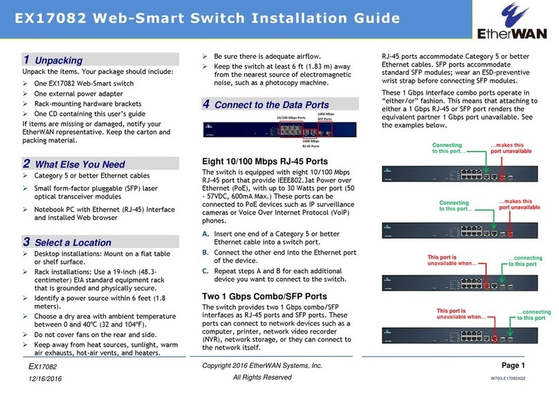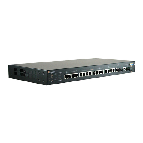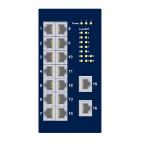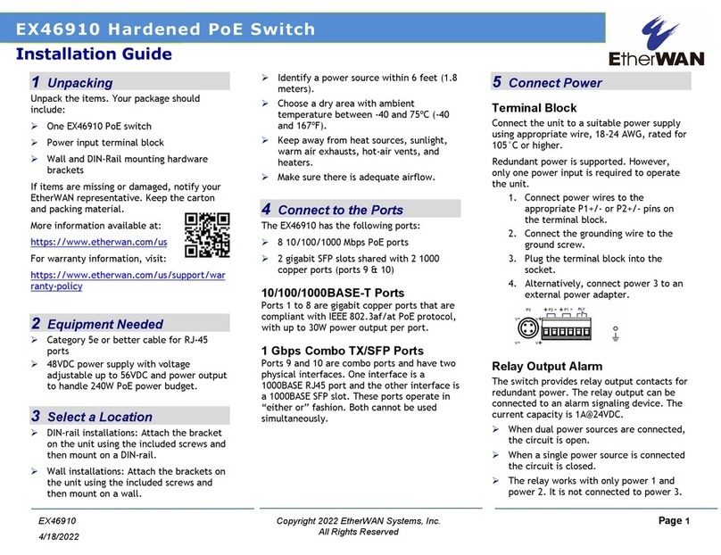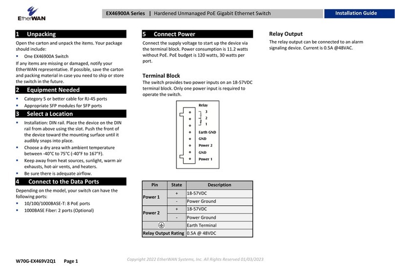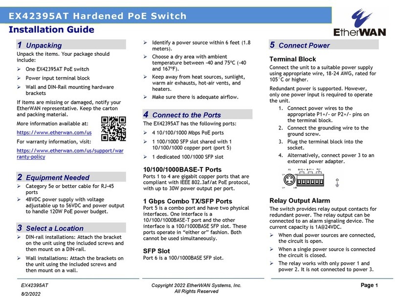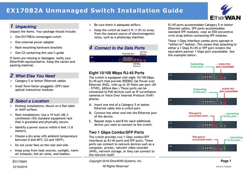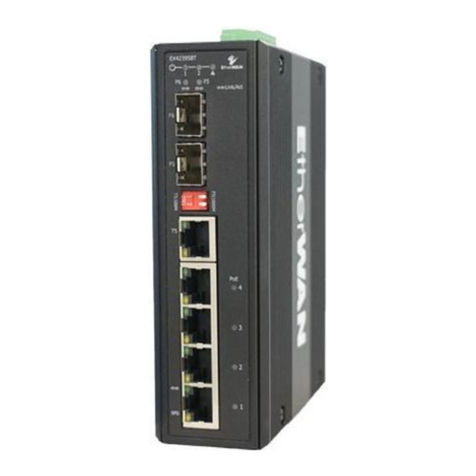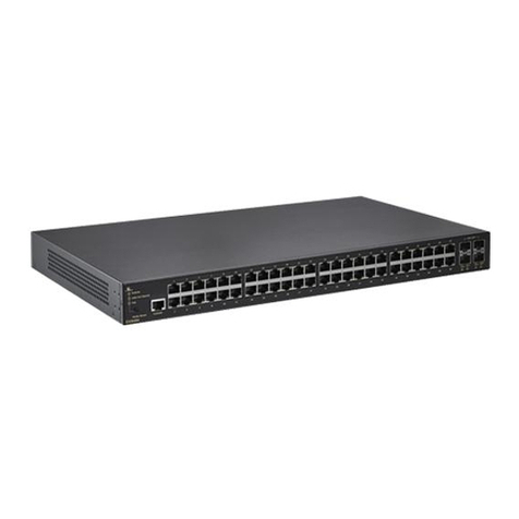
EX16926 GigabitEthernetSwitch www.etherwan.com
2 V1
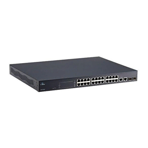
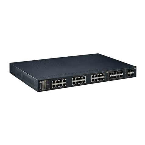
The switch may standalone, or may be mounted in a standard 19” rack. Rack mounting produces an
orderly installation when you have a number of related network devices. The switch is supplied with two
optional rack mounting brackets and screws, which are used for rack mounting the unit.
order to uplink various other networking devices for a gigabit link that may span great distances.
You can change transceivers while the switch is operating and use different transceivers to connect to
Ethernet switches with different types of fiber-optic or even copper cable connectors.
The SFP module is a hot-pluggable transceiver and specified by a multi-source agreement (MSA). See the
SFF committee’s INF-8074i specification Rev 1.0 for details.
802.3az ON/OFF Button
The IEEE802.3az ON/OFF button helps reducing the power consumption of switch. This button allows
users to keep the best performance without transmission impacted or to have the green support of Energy
Efficient Ethernet mode with the simple push of a button.
Rear Panel
The three-pronged power receptacle is located on the rear panel of the switch.
The rear panel of the switch is shown as below.
Power Receptacle
To be compatible with the electric service standards around the world, the switch is designed to afford the
power supply in the range from 100 to 240VAC, 50/60Hz. Please make sure that your outlet standard to be
within this range.
To power on the switch, connect one end of the supplied power cord to the power receptacle on the back of
the switch and the other end to the appropriate power source. After the power cord installation, please
check if the power LED is illuminated for a normal power status.
Installation
This switch can be placed on your desktop directly, or mounted in a rack. The installation is a snap. Users
can use all the features of the switch with simply attaching the cables and turning the power on.
Before installing the switch, we strongly recommend:
The switch is placed with appropriate ventilation environment. A minimum 25mm space around the
unit is recommended.
The switch and the relevant components are away from sources of electrical noise such as radios,
transmitters and broadband amplifiers.
The switch is away from environments beyond recommend moisture.
Desktop Installation
Attach the provided rubber feet to the bottom of the switch to keep the switch from slipping. The
recommend position has been square-marked.
Install the switch on a level surface that can support the weight of the unit and the relevant
components.
Plug the switch with the female end of the provided power cord and plug the male end to the power
outlet.
Rack-mount Installation
Rack-mount Installation Requirements:
Two mounting brackets.
Six M3 flat head screws
Procedures to Rack-Mount the switch in the rack:
First disconnect all the cables from the switch.
Place the unit the right way up on a hard, flat surface with the front facing you.
Locate a mounting bracket over the mounting holes on one side of the unit.
Insert the screws and fully tighten with a suitable screwdriver.
Repeat the two previous steps for the other side of the unit.
Insert the unit into the rack with suitable screws.
Reconnect all the cables.
Network Cables
Crossover or straight-through cable: All the ports on the switch support Auto-MDI/MDI-X
functionality. Both straight-through or crossover cables can be used to connect the switch with PCs
as well as other devices like switches, hubs or router.
Category 3, 4, 5, 5e, 6 UTP/STP cable: To make a valid connection and obtain the optimal
performance. Appropriate cables corresponding to different transmitting/receiving speed is
required. To choose a suitable cable, please refer to the following table.
Media Speed
(Mbps) Wiring
10 Category 3, 4, 5 UTP/STP
100 Category 5 UTP/STP
10/100/1000Mbps copper
1000 Category 5e, 6 UTP/STP
1000Mbps Fiber
(Mini GBIC required) 1000 The cable type differs from the mini-GBIC you purchase.
Please refer to the instruction that came with your mini-GBIC.
