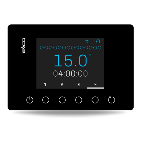
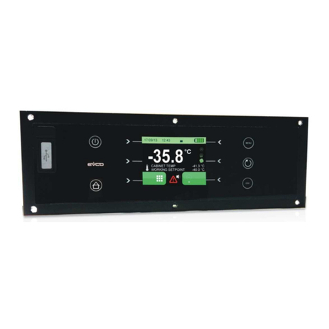
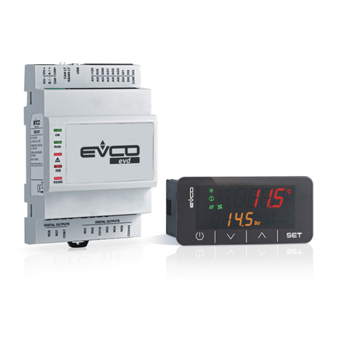
Evco c-pro 3 micro AHU Instructions for use

EVCO S.p.A. c-pro 3 micro AHU/c-pro 3 kilo AHU | Application Manual ver. 1.1 | Code 144CP3UKAHE104
page 1 of 104
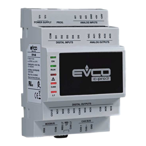
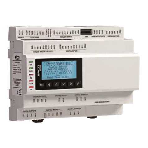
c-pro 3 micro AHU
c-pro 3 kilo AHU
PROGRAMMABLE CONTROLLERS FOR AIR
HANDLING UNITS
ENGLISH
APPLICATION MANUAL ver. 1.0
CODE 144CP3UKAHE104

EVCO S.p.A. c-pro 3 micro AHU/c-pro 3 kilo AHU | Application Manual ver. 1.1 | Code 144CP3UKAHE104
page 2 of 104
Important
Important
Read this document thoroughly before installation and before use of the device and follow all recommendations; keep
this document with the device for future consultation.
The following symbols support reading of the document:
Indicates a suggestion
Indicates a warning.
The device must be disposed of in compliance with local Standards regarding the collection of electric and electronic
equipment.

EVCO S.p.A. c-pro 3 micro AHU/c-pro 3 kilo AHU | Application Manual ver. 1.1 | Code 144CP3UKAHE104
page 3 of 104
Index
1GENERALITIES....................................................................................................................................... 6
1.1 Description........................................................................................................................................ 6
1.2 Applications....................................................................................................................................... 6
2User interface ........................................................................................................................................ 6
2.1 Dimensions of the controllers............................................................................................................... 7
2.1.1 Control module c-pro 3 micro AHU dimensions .............................................................................. 7
2.1.2 Control module c-pro 3 kilo AHU dimensions ................................................................................. 7
2.2 User interface (Vroom)........................................................................................................................ 8
2.3 User interface (remote) Vroom............................................................................................................. 9
2.3.1 Screens and keypads visible from Vroom ...................................................................................... 9
2.4 Display that can be viewed from the Vroom interface............................................................................ 10
3List of pages ........................................................................................................................................ 11
3.1 Password......................................................................................................................................... 12
3.2 Main page ....................................................................................................................................... 12
3.2.1 Status pages ........................................................................................................................... 12
3.2.2 (TIME BANDS) screen............................................................................................................... 13
3.2.3 Fans Screen ............................................................................................................................ 13
3.2.4 Regulation status of coil 1 screen............................................................................................... 14
3.2.5 Regulation status of coil 2 screen............................................................................................... 14
3.2.6 Direct expansion coil regulation status screen.............................................................................. 14
3.2.7 Heating elements status screen ................................................................................................. 15
3.2.8 Humidity regulation status screen .............................................................................................. 15
3.2.9 Status screen of the damper for air circulation............................................................................. 15
3.2.10 Heat recovery status screen.................................................................................................. 16
3.2.11 Circulation pumps status screen ............................................................................................ 16
3.2.12 Sensors status screen .......................................................................................................... 16
3.3 General menu.................................................................................................................................. 17
3.4 User menu....................................................................................................................................... 17
3.5 Maintenance menu ........................................................................................................................... 17
3.6 Installation menu ............................................................................................................................. 18
3.7 RTC menu ....................................................................................................................................... 19
3.8 Alarms menu ................................................................................................................................... 19
3.9 Project and firmware versions............................................................................................................ 20
4Parameter list ...................................................................................................................................... 21
4.1 List of configuration parameters......................................................................................................... 22
4.1.1 AI parameters I/O table............................................................................................................ 40
4.1.2 DI parameters I/O table............................................................................................................ 41
4.1.3 DO parameters I/O table........................................................................................................... 42
4.1.4 AO parameters I/O table........................................................................................................... 42
5Regulations.......................................................................................................................................... 43
5.1 Machine status................................................................................................................................. 43
5.2 Alarm OFF status.............................................................................................................................. 44
5.3 Unit type......................................................................................................................................... 44
5.4 Electric connections.......................................................................................................................... 45
5.4.1 Machine electric connections with double flow.............................................................................. 45
5.5 Electric connections.......................................................................................................................... 47
5.5.1 Machine electric connections with single flow............................................................................... 47

EVCO S.p.A. c-pro 3 micro AHU/c-pro 3 kilo AHU | Application Manual ver. 1.1 | Code 144CP3UKAHE104
page 4 of 104
5.6 Operating mode control..................................................................................................................... 49
5.7 Setting the RTC................................................................................................................................ 50
5.8 Plant set-up..................................................................................................................................... 50
5.8.1 Set-up of the heat recovery device............................................................................................. 50
5.8.2 Set-up of the fans.................................................................................................................... 51
5.8.3 Set up of Coil 1 type configuration ............................................................................................. 51
5.8.4 Set up of Coil 2 type configuration ............................................................................................. 52
5.9 Table of types of configurable machines.............................................................................................. 54
5.10 Fans ............................................................................................................................................... 58
5.10.1 Continuous control............................................................................................................... 58
5.10.2 Continuous/On Off control..................................................................................................... 58
5.10.3 Control On/Off..................................................................................................................... 59
5.10.4 Modulating regulation........................................................................................................... 60
5.10.5 Modulating control with steps to enable .................................................................................. 61
5.10.6 Static Pressure control.......................................................................................................... 62
5.10.7 Minimum/Maximum discharge temperature............................................................................. 63
5.10.8 "Intake cycles" .................................................................................................................... 63
5.10.9 Fan status........................................................................................................................... 64
5.10.10 Fan alarm inputs.................................................................................................................. 64
5.10.11 Environment temperature robe in error mode............................................................................. 64
5.11 Main controls ................................................................................................................................... 65
5.12 Cooling and heating controls.............................................................................................................. 66
5.12.1 Floating set point floating from flow ....................................................................................... 66
5.12.2 Modulating valve control....................................................................................................... 67
5.13 Post-heating .................................................................................................................................... 68
5.13.1 Post-heating coil for hot water............................................................................................... 68
5.13.2 Electrical post heating coil..................................................................................................... 68
5.13.3 Status of post-heating heating elements................................................................................. 69
5.14 Dehumidification .............................................................................................................................. 70
5.14.1 Dehumidification control ....................................................................................................... 70
5.14.2 Limit regulation of dehumidification........................................................................................ 71
5.15 Humidification.................................................................................................................................. 73
5.15.1 Enabling humidifier (flow temperature operation) .................................................................... 73
5.15.2 Humidifier On/Off ................................................................................................................ 73
5.15.3 Maximum humidification control ............................................................................................ 74
5.15.4 Maximum humidity protection ............................................................................................... 74
5.15.5 Humidifier status ................................................................................................................. 74
5.16 Dampers ......................................................................................................................................... 75
5.16.1 Damper modulating regulation .............................................................................................. 75
5.16.2 Control in fixed opening........................................................................................................ 75
5.16.3 EnablingFree-Cooling/Free-Heatingintemperature............................................................................ 76
5.16.4 Free-Cooling and Free-Heating Control ................................................................................... 77
5.16.5 Air quality control ................................................................................................................ 78
5.16.6 Damper command ............................................................................................................... 78
5.16.7 Damper status..................................................................................................................... 79
5.17 Heat recovery devices....................................................................................................................... 80
5.17.1 Heat recovery devices at cross flow........................................................................................ 80
5.17.2 Heat recovery devices with double coil ................................................................................... 81
5.17.3 Rotating heat recovery device ............................................................................................... 82
EVCO S.p.A. c-pro 3 micro AHU/c-pro 3 kilo AHU | Application Manual ver. 1.1 | Code 144CP3UKAHE104
page 5 of 104
5.17.4 Recovery device status......................................................................................................... 83
5.18 Heating/cooling pumps ..................................................................................................................... 83
5.18.1 Continuous control............................................................................................................... 83
5.18.2 Control On/Off..................................................................................................................... 83
5.18.3 Pump status........................................................................................................................ 84
5.18.4 Pump alarm inputs............................................................................................................... 84
5.19 Unit with single heating-cooling coil (seasonal) .................................................................................... 85
5.19.1 Right coil steps status .......................................................................................................... 85
5.19.2 Primary control.................................................................................................................... 85
5.20 Management (various)...................................................................................................................... 86
5.20.1 Single or distinct set point..................................................................................................... 86
5.20.2 Compensation for set point ................................................................................................... 86
5.20.3 Variation set point from supervisor......................................................................................... 87
5.20.4 Manual fan operation............................................................................................................ 87
5.21 Time schedule.................................................................................................................................. 87
5.22 Miscellaneous management ............................................................................................................... 87
5.22.1 Last date of maintenance...................................................................................................... 87
5.22.2 Restore default parameters................................................................................................... 87
6Diagnostics.......................................................................................................................................... 88
6.1 Manual and automatic alarms ............................................................................................................ 88
6.1.1 Manual-reset alarms................................................................................................................. 88
6.1.2 Automatic-reset alarms............................................................................................................. 88
6.2 Table of Alarms................................................................................................................................ 89
6.2.1 Air flow switch alarm................................................................................................................ 90
6.2.2 Anti-freeze alarm..................................................................................................................... 91
6.3 Alarm relay...................................................................................................................................... 91
6.4 Alarms log....................................................................................................................................... 91
7List of Modbus® variables ..................................................................................................................... 92
7.1 c-pro 3 micro/kilo AHU version........................................................................................................... 92

EVCO S.p.A. c-pro 3 micro AHU/c-pro 3 kilo AHU | Application Manual ver. 1.1 | Code 144CP3UKAHE104
page 6 of 104
1GENERALITIES
1.1 Description
The programmable controllers of the c-pro 3 micro AHU/ c-pro 3 kilo AHU series are devices studied for the
management of air handling units with seasonal and annual operation.
they use programmable controllers of the c-pro 3 series, the user interface of the Vroom series and are programmed
through an application software developed in UNI-PRO 3 environment.
The controllers are available in the blind version and can be powered both con direct and alternating current, with 12
VAC power supply in the case of the: c-pro 3 micro AHU and with 24 VAC/DC power supply in the event of the
controller: c-pro 3 kilo AHU.
The controllers can manage air handling units with seasonal operation (with one coil, cooling or heating) and with
annual operation (with two coils, cooling, heating and post heating).
Through the programming port it is possible to make the upload and the download of the configuration parameters
(using the USB pen drive); through the RS-485 one, with MODBUS communication protocol, it is possible to connect
the devices to the set-up software system Parameters Manager or to the plants monitoring and supervision one RICS
(through a serial interface) instead.
Among the several functions one highlights the management of the humidification, of the bypass damper and of the
working set point compensation.
1.2 Applications
The following controllers are able to manage the following unit types:
-Air handling units that make use of c-pro 3 micro AHU
-Air handling units that make use of c-pro 3 kilo AHU
2User interface
A unique interface is available for the application:
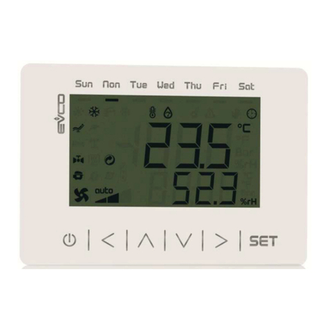
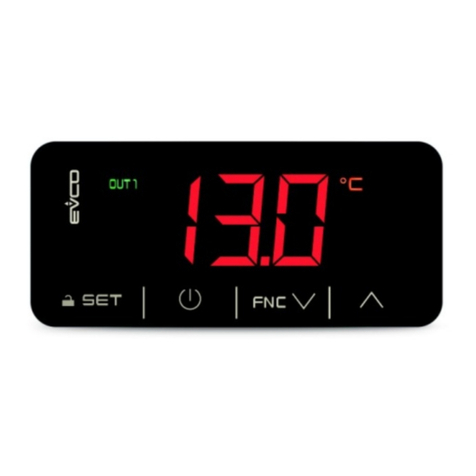
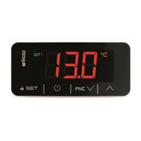
-Remote LCD-display interface VroomTH.
The Vroom has 6 navigation/page modification keys, of the states and enabling of the same.
A description of the keys used by the application is available; see reference paragraph to Vroom interface.

EVCO S.p.A. c-pro 3 micro AHU/c-pro 3 kilo AHU | Application Manual ver. 1.1 | Code 144CP3UKAHE104
page 7 of 104
2.1 Dimensions of the controllers
2.1.1 Control module c-pro 3 micro AHU dimensions
4 DIN modules, the dimensions are expressed in mm (in). Molex-fit terminal board.
2.1.2 Control module c-pro 3 kilo AHU dimensions
4 DIN modules, the dimensions are expressed in mm (in). Removable spring terminal boards
The c-pro 3 micro AHU/c-pro 3 kilo AHU controllers scan be managed via the Vroom interface.

EVCO S.p.A. c-pro 3 micro AHU/c-pro 3 kilo AHU | Application Manual ver. 1.1 | Code 144CP3UKAHE104
page 8 of 104
2.2 User interface (Vroom)
There are the three following possibilities for mounting the user interface (remote) Vroom:
2.2.1.1 Recessed in the wall in 506E box (Rotated by 90°)
2.2.1.2 Wall installation, on Evco CPVW00 support
2.2.1.3 Panel installation

EVCO S.p.A. c-pro 3 micro AHU/c-pro 3 kilo AHU | Application Manual ver. 1.1 | Code 144CP3UKAHE104
page 9 of 104
2.3 User interface (remote) Vroom
2.3.1Screens and keypads visible from Vroom
The keyboard features 6 page-navigation and value-editing keys, which have the following functions:
- and (UP/ DOWN): during editing, it modifies parameters; otherwise, it moves the cursor
- and (LEFT/RIGHT): it displays the pages of the same level in succession.
In the Vroom pages, the icons are the same of the Built-In LCD Display.
- (SET/ENTER): during editing, it confirms the value; otherwise, it sends any commands associated to the text
on which the cursor is positioned.
If pressed down and held for about 2 seconds, the ENTER key allows access to the main menu
If held down during display of an alarm page, this key allows to reset the alarm When alarm pages are displayed, any
key pressed allows to scroll the active alarms.
- (Stand-BY/ESC): during editing, it cancels the value; otherwise, it requests any default page that might be
associated to the actual page.
If pressed and held for 2 seconds, the ESC key allows to switch the machine on and off.
If pressed when on the main page, the key allows to access the list of active alarms.
The main features of the interface are the possibility to communicate to the user a great deal of information and the
remarkable ease of control:
- Vroom has a 128 x 64 pixel single colour LCD graphic display.
Vroom constructive features allows, panel mounting (also in applications where a IP65 protection is required) and wall
mounting, solutions.

EVCO S.p.A. c-pro 3 micro AHU/c-pro 3 kilo AHU | Application Manual ver. 1.1 | Code 144CP3UKAHE104
page 10 of 104
2.4 Display that can be viewed from the Vroom interface
From the ages of the LCD screen of the associated user interface (Vroom), the following icons can be displayed:
Winter/Summer icon:
Winter: Winter operation active.
Summer: Summer operation active.
Alarm icon:
Invisible: No alarm.
Visible: At least 1 alarm is active.
Slow flashing: New alarm exists, but it is not displayed yet.
Scheduler icon:
Invisible: No time bands active.
T1: Time band T1 active.
T2: Time band T2 active.
T3: Time band T3 active.
H: Time band Holiday active.
Fan icon:
Invisible: Fans are off.
Visible: At least 1 fan is on.
Pump icon:
Invisible: Pumps are off.
Visible: At least 1 pump is on.
Coil icon:
Invisible: Coils are off.
Visible: At least 1 coil is on.
Damper icon:
Invisible: Damper is closed
Visible: Damper is open.
°C/°F icon: This indicates the temperature measurement unit of the selected sensor.

EVCO S.p.A. c-pro 3 micro AHU/c-pro 3 kilo AHU | Application Manual ver. 1.1 | Code 144CP3UKAHE104
page 11 of 104
3List of pages
This chapter describes the main pages and menus featured in the application. As already described earlier, the general
menu is subdivided into four submenu levels: user, maintenance operator, installation operator, and configuration.
The menu structure is the following:
- General menu
- Time bands (Level 1)
- User menu (Level 1)
- Maintenance operator menu (Level 2)
- Regulations branch maintenance menu
- Manual branch maintenance menu
- Calibration branch maintenance menu
- Installation operator menu (Level 3)
- Control branch installation menu
- Fan branch installation menu
- Heating-Cooling coil branch installation menu
- Humidifier branch installation menu
- Dampers branch installation menu
- Heat recovery device branch installer menu
- Pump branch installer menu
- Protection device branch installation menu
- Modbus parameter branch installer menu
- Various parameters branch installer menu
- Default branch installation menu
- Configuration parameters branch installer menu
- Hardware AI parameters installer menu
- Hardware DI parameters installer menu
- Hardware AO parameters installer menu
- Hardware DO parameters installer menu
- RTC menu (Level 0)
- ALARMS menu (Level 0)
- Show alarms
- HISTORY menu (Level 0)
- Show alarm history
- SAVE/RESTORE menu (Level 3)

EVCO S.p.A. c-pro 3 micro AHU/c-pro 3 kilo AHU | Application Manual ver. 1.1 | Code 144CP3UKAHE104
page 12 of 104
3.1 Password
A level is assigned to every menu that determines the accessibility to the various functions, via the password.
Once the correct password is introduced, it is possible to access the protected functions, release the respective level
and finally release the relative sub-levels. The level passwords can be modified by the same or also by upper levels,
e.g. by the Manufacturer level it will be possible to modify the passwords of the lower levels.
To set a password, the range of values possible goes from -999 / 9999.
The valid interval for setting each individual password expires every 4 minutes, after which a new one must be set.
3.2 Main page
The status of the machine will determine a different display of the main page, i.e. it may be on or off.
If the machine is switched OFF, Unit OFF is displayed, with indication of the cause for the shutdown (dedicated key,
lack of consensus from digital input, supervisor, scheduler).
If the machine is switched ON, the room temperature and humidity value are displayed. If the probe is faulty of
disconnected, the display will show: “----”.
Pressing the RIGHT or LEFT keys from the main page, the information relative to the status of the circuit, of the RTC
and the probes configured are also displayed.
In the case of a probe error, the field of the value itself will display: “---- “ or “....” if this is disabled.
3.2.1 Status pages
Once the controller is on, the ON screen will be displayed from the remote user interface Vroom, with the graphical
icons of the statues managed by the controller.
The graphical icons shown above are briefly described, starting from the first in the bottom left, proceeding to the
right.

EVCO S.p.A. c-pro 3 micro AHU/c-pro 3 kilo AHU | Application Manual ver. 1.1 | Code 144CP3UKAHE104
page 13 of 104
1) Summer/winter/alarm
2) T1/T2/T3/Holiday/Economy(DI) time band
3) V1/V2/V3/Analogue flow fan
4) At least 1 water coil is on.
5) RH coil steps
6) At least 1 resistor on (or analogue >0)
7) External air DO damper open/mixing chamber damper AO>0
Pressing the ESC key from this page brings the user to the Alarm/History page.
Following the ON screen, the individual status pages can be displayed (via LEFT/RIGHT), only and exclusively of the
status in which the utilities are configured (except time bands and probes always present).
3.2.2 (TIME BANDS) screen
In this screen via "Actual TB" displays the current time band in use, while with “Actual offS", the active offset.
3.2.3 Fans Screen
the following can be displayed in this screen status and speed of the flow and return fans

EVCO S.p.A. c-pro 3 micro AHU/c-pro 3 kilo AHU | Application Manual ver. 1.1 | Code 144CP3UKAHE104
page 14 of 104
3.2.4 Regulation status of coil 1 screen
The regulation status of coil 1 is displayed
3.2.5 Regulation status of coil 2 screen
The regulation status of coil 2 is displayed
3.2.6 Direct expansion coil regulation status screen
The regulation status of the direct expansion coil is displayed

EVCO S.p.A. c-pro 3 micro AHU/c-pro 3 kilo AHU | Application Manual ver. 1.1 | Code 144CP3UKAHE104
page 15 of 104
3.2.7 Heating elements status screen
The status of the heating elements is displayed
3.2.8 Humidity regulation status screen
The status of the humidity regulation is displayed in this screen
3.2.9Status screen of the damper for air circulation
The air circulation damper status (Free-cooling/Heating) and air quality is displayed.

EVCO S.p.A. c-pro 3 micro AHU/c-pro 3 kilo AHU | Application Manual ver. 1.1 | Code 144CP3UKAHE104
page 16 of 104
3.2.10 Heat recovery status screen
The status of the heat recovery is displayed
3.2.11 Circulation pumps status screen
The circulation pumps status can be displayed
3.2.12 Sensors status screen
The status of the sensors is displayed

EVCO S.p.A. c-pro 3 micro AHU/c-pro 3 kilo AHU | Application Manual ver. 1.1 | Code 144CP3UKAHE104
page 17 of 104
3.3 General menu
The general menu has no level and represents the access point for all the other system menus.
TIME BANDS
USER
MAINTENANCE
INSTALLATION
RTC
ALARMS
HISTORY
SAVE/RESTORE
It is possible to view this menu from any point within the user interface by pressing ENTER for approximately 2
seconds. From this menu you can choose the menu you wish to view by pressing the UP and DOWN keys followed by
pressing the ENTER key for confirmation.
In the upper right hand corner of the image appears a “v” which represents the focus.
This indication specifies to the user that additional information is contained therein and can be viewed by pressing the
DOWN key (or UP key depending on the direction of the focus) scrolling to view the content that is not viewable in the
current page. In this specific case, once the focus is on the line CONSTRUCTOR, press DOWN to proceed to the
subsequent page.
3.4 User menu
The User menu is a Level 1 menu, i.e. it requires entering of the User level (or higher) password, in order to be able to
display/modify the parameters contained in this branch.
The following parameters appear in this branch:
- summer/winter operating mode
- set point for winter operation or single set point
- set point for summer operation
- set point room humidity
- offset from supervisor
- offset from scheduler
- USER password
3.5 Maintenance menu
The Maintenance menu is a Level 2 menu, i.e. it requires entering of the Maintenance operator level (or higher)
password, in order to be able to display/modify the parameters contained in this branch.
CONTROL
MANUAL
CALIBRATION
I/O STATUS
MAINTENANCE MENU Password
In this menu, it is possible to view the status of the various devices, inputs and outputs utilized by the application.
In the REGULATIONS menu, it is possible to view/enable the features relating to the operation of fans and pumps. Some
examples of these are the hours of operation, the enabling of the corresponding alarms and the threshold of maximum
allowable hours.

EVCO S.p.A. c-pro 3 micro AHU/c-pro 3 kilo AHU | Application Manual ver. 1.1 | Code 144CP3UKAHE104
page 18 of 104
The operating value of the fan in manual mode and the steps can be set in the MANUAL menu.
In the CALIBRATION menu, it is possible to set the corrections to be applied to analogue inputs, to compensate the
offsets due to cabling and sensor positioning.
In the I/O STATUS menu, it is possible to view directly the card’s physical inputs and outputs.
3.6 Installation menu
The installation menu is a Level 3 menu, i.e. it requires entering of the installation level (or higher) password, in order
to be able to display/modify the parameters contained in this branch.
CONTROL
FANS
HEATING-COOLING COILS
HUMIDIFIER
DAMPERS
HEAT RECOVERY DEVICE
PUMP
PROTECTION DEVICE
MODBUS PARAMETERS
VARIOUS PARAMETERS
DEFAULT
INSTALLATION MENU password
CONFIGURATION PARAMETERS
HARDWARE AI PARAMETERS
HARDWARE DI PARAMETERS
HARDWARE AO PARAMETERS
HARDWARE DO PARAMETERS
The installation Menu contains all the parameters related to the configuration of all operations (alarms, control, logic,
characteristics) used for this device. By pressing the ENTER key on the text which reads “INSTALLATION MENU” you
will come to a page allowing you the option to change your password (PSd3)
In the CONTROL Menu you can set/view parameters for various specific controls:
- compensation control set point
- sniffing cycles for air room temperature acquisition
Within the FANS, HEATING-COOLING COILS, HUMIDIFIER, DAMPERS HEAT RECOVERY DEVICE and PUMPS menus you
may set the related parameters to manage the devices:
- control parameters
- timing
- operation
The PROTECTION DEVICE menu contains all parameters connected with alarms and management of safety devices
which protect the refrigerating circuit:
- activations
- reporting delays
- type of reset
- alarms signal
The MODBUS menu contains all parameters for configuration of the network.
The VARIOUS menu contains other general parameters:

EVCO S.p.A. c-pro 3 micro AHU/c-pro 3 kilo AHU | Application Manual ver. 1.1 | Code 144CP3UKAHE104
page 19 of 104
- Set maximum threshold values
- Set Modbus communication
- Enable secondary Set Point of change-over and supervisor
- Enable summer/winter modes from Digital inputs and supervisor
- Enable sensors
- Set logic for digital input/output
- Reset history
- Set unit of measurement
- Set sensor type: return temperature, flow, external, humidity, channel pressure, air quality, flow humidity,
potentiometer, input logic, coil 1, coil 2, fan, damper, humidifier, heating elements, recovery device
From the DEFAULT PARAMETER menu it is possible to restore the default values of all parameters of the application
and save or download from the USB pen drive.
This menu is only accessible when the device is off.
The CONFIGURATION PARAMETERS Menu allows you to set/view the parameters relating to the characteristics of the
machine.
-Unit type
-Number of coils
-Enable devices
In the HARDWARE AI there are parameters relative to the use of the AI.
In the HARDWARE DI there are parameters relative to the use of the DI.
In the HARDWARE AO there are parameters relative to the use of the AO.
In the HARDWARE DO there are parameters relative to the use of the DO.
3.7 RTC menu
This menu contains the functionality of the systems Real Time Clock:
SETTING THE REAL TIME CLOCK
3.8 Alarms menu
This menu allows viewing and acknowledging of alarms.
SHOW ALARMS
SHOW ALARM HISTORY
The SHOW ALARMS menu shows the active alarms. Each time the DOWN key is pressed, the next active alarm is
shown. If no alarms are present, the message “NO ALARMS” is displayed.
The alarm can be acknowledged by pressing the ENTER key for 2 seconds, when the alarm condition is not active
anymore.
The alarm history page will show the latest alarm. To view the preceding alarm press ENTER key. This can be repeated
until the first alarm is displayed. The history is viewed in a circular manner.
By pressing the ESC key or after 60 seconds of no key activity, the main page will be displayed.

EVCO S.p.A. c-pro 3 micro AHU/c-pro 3 kilo AHU | Application Manual ver. 1.1 | Code 144CP3UKAHE104
page 20 of 104
3.9 Project and firmware versions
Press simultaneously the UP+DOWN keys for about 2 seconds, then press the ENTER key on the InFolabel.
Information on the project and controller firmware versions is displayed sequentially, namely:
Project Number <-> Project Version <-> Project Revision <->
Firmware Number <-> Firmware Version <-> Firmware Revision <->
To scroll this information, use the UP and DOWN keys. To return to the application pages, press the ESC key.
Other manuals for c-pro 3 micro AHU
2
This manual suits for next models
1
Table of contents
Other Evco Controllers manuals

Evco
Evco c-pro 3 micro AHU User manual

Evco
Evco EV3221 User manual

Evco
Evco EV3802 User manual

Evco
Evco EV3 Basic Split User manual

Evco
Evco EV3B71 User manual

Evco
Evco EV3B23 User manual

Evco
Evco C-pro 3 giga User manual

Evco
Evco EVF 300 Series User guide

Evco
Evco EVJ 200 Series User manual

Evco
Evco EVX 800 Series User guide

Evco
Evco Vcolor 869 User guide

Evco
Evco Vcolor 318 M User guide

Evco
Evco EVK204 User manual

Evco
Evco EV8338 User manual

Evco
Evco Vcolor 338 S User guide

Evco
Evco Vcolor 279 Instructions for use

Evco
Evco EVXV 800 Series User guide

Evco
Evco EV3 CHIL User manual

Evco
Evco EV3 700 Series User manual

Evco
Evco EVF205 User manual