1
The 760 Gate Automation System
The FAAC 760 automation system consists of a monoblock hydraulic unit and foundation
box assembly. The system is designed for underground installation, and will not alter the
appearance of the gate.
CONTENTS
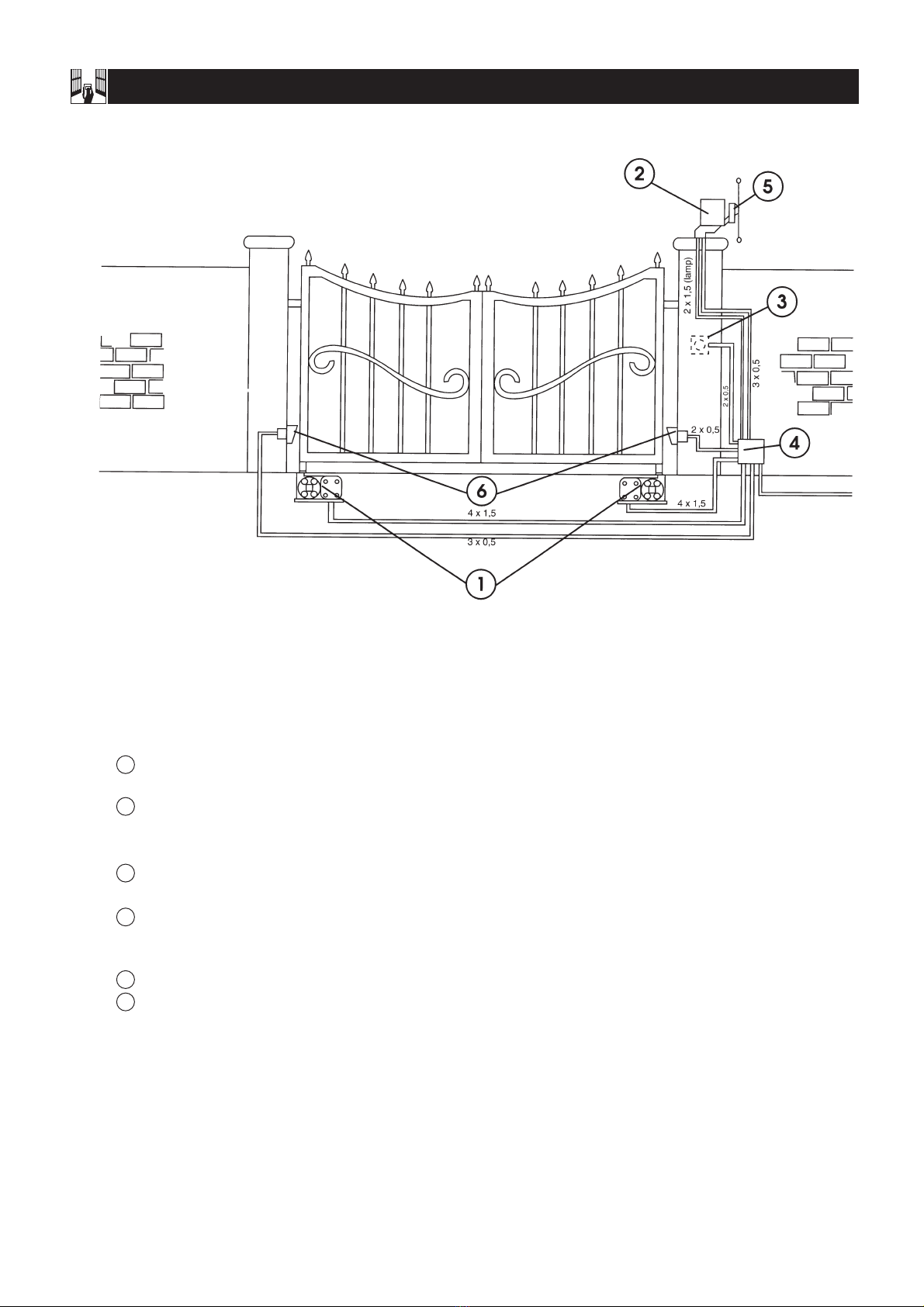
1. Typical Installation Schematic
2. Technical Specifications
3. Description and Technical Specification
3.1 Maximum Duty Cycle Curve
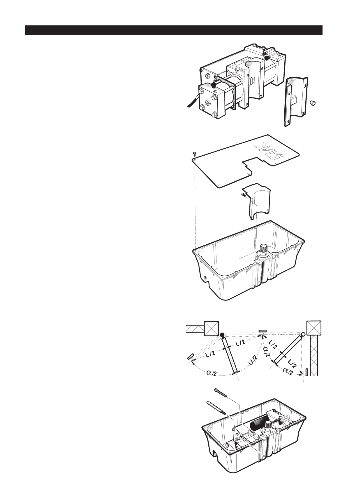
4. Installation
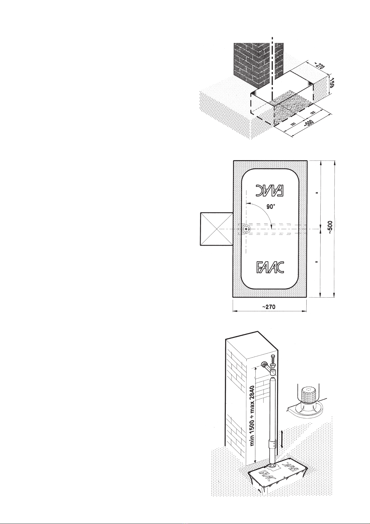
4.1 Preliminary checks
4.2 Installation of leaf supporting foundation box
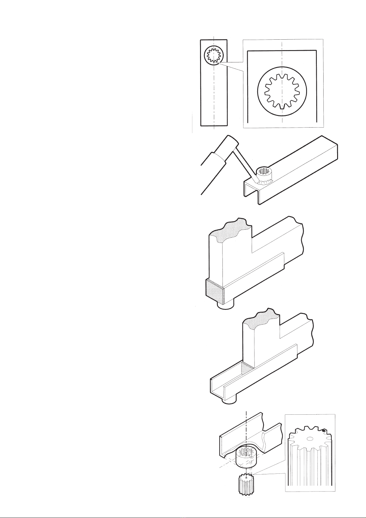
4.3 Setting up the gate
5. Start-up
5.1 Adjustment of the anti-crushing device
5.2 Adjustment of the internal travel stop screws (760 CR only)
5.3 Adjustment of deceleration ramp (760 CR only)
6. Angles of operation below 90°
7. Manual operation
8. Maintenance
General Safety Standards
• Read the instructions carefully before installing the gate automation system. Keep these instructions for future reference.
• Installation, electrical wiring and adjustments must be carried out in compliance with current safety standards.
• FAAC cannot be held responsible for failure to observe technical standards in the construction of gates, or for any deformation of the gates
which may occur during use.
•Before installing the gate automation system, make all necessary structural modifications to ensure safety clearances, and for the protection
and/or isolation of all cutting, entrapment, and crushing areas.
•This equipment should be defined only to the use for which it has been expressly conceived (all equipment), any other use should be
considered improper and therefore dangerous. The manufacturer cannot be held responsible for eventual damage caused by improper,
incorrect and unreasonable use.
• Do not use this device in areas subject to explosion: the presence of flammable gases or fumes is a serious hazard.
• Before carrying out any cleaning or maintenance operations, unplug the equipment from the electrical supply network either by removing
the plug or by turning off the system’s main switch.
•An isolation switch should be provided for the installation according to by current safety regulations with an opening distance of 3 mm or
more on the part of the contacts. Alternatively, use a 6A thermo-magnetic breaker with multi-pole switching.
• Ensure that there is a differential switch up-line of the electrical system, with a trip threshold of 0.03A.
• Check that the earthing plant is in perfect condition and connect it to the gate frame. Also earth the yellow/green wire of the operator.
•The end-user must avoid any attempt to repair or adjust the automation system; these operations must be carried out exclusively by
qualified personnel.
•Use only FAAC original spare parts for maintenance operations.
•Do not carry out any modifications to automation components.
•Packaging material (plastic, polystyrene etc.) is a potential hazard and must be kept out of reach of children
•The installer must supply all information regarding manual operation of the system in the event of an emergency and provide the end-user
with the leaflet attached to the product.
•The operator is fitted with an anti-crush safety system, this is a torque control device which guarantees ultimate safety and reliability if properly
adjusted
•In any event, FAAC always recommends the installation of other safety devices, taking into consideration current safety standards, installation
site, system operation logics, dimensions and weight of the gate.
• The safety devices (e.g photocells, safety edges, etc.) will protect the crushing and entrapment areas and general potential hazard areas of
the automation.
•Each installation must be fitted with at least one flashing light (e,g, FAAC LAMP, MINILAMP etc,) as well as a warning plate suitably fixed to the
gate.
•FAAC UK Ltd. accepts no responsibility for damage or injury resulting from the incorrect use of this gate automation system.