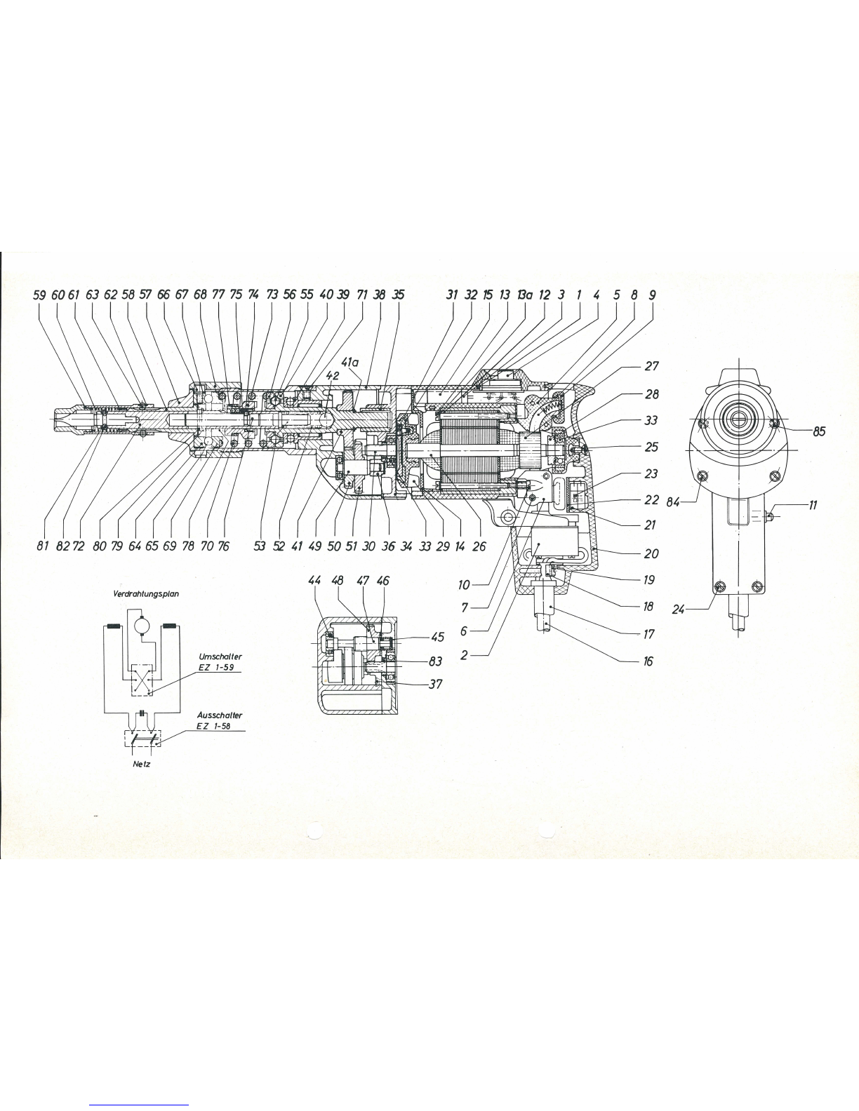
Fein ASsd 636-1 User manual

ASsd
636-1
To be handed to the workshop
Operating instructions
for the Electric Screw-Driver type ASsd 636-1
and for type ASsd 736-1
(42
Volts)
1.
Technical
data
Current:
~
(single
phase
AC)
for
iron
screws
T
oo
l
holder
Input
Type
up
to
Speed
R.P.M.
Watts
mm
Net
weight
in.
I
mm
full
load
ASsd
636-1
ASsd
736-1
,,4
6 450
2.
Construction
This
screwdriver
is
an
electric
tool
of
class
II
with
protective
insulation
without
earth
wire
and
is
in
accordance
with
the
VDE
regulations
0740.
The
protective
insulation
is
attained
by
the
shockproof
motor
housing
made
of
Polyamide
-
and
by
insulat-
ing
the
armature
against
the
pinion.
The
protective
insulation
is
t
ested
with
the
prescribed
test
voltage
of
4000 V.
The
machine
is
radio
suppressed
in
accordance
with
radio
interference
VDE
0875.
It
is
supplied
with
a
two-core
cable
without
earth
wire
and
must
not
be
earthed.
Type
ASsd
736-1
for
low
tension
(42
Volts)
is
of
the
same
design,
but
without
protectiv
e
insulation.
Th
e
machine
is
provided
with
a
reversing
switch
for
clockwise
and
anticlockwise
rotation.
It
must
not
be
operated
when
the
machine
is
running
.
To
prevent
the
overbridging
of
the
insulation
no
additional
marking
plates
and
signs
must
be
riveted
or
screwed
on
the
housing.
We
recommend
the
use
of
transfers
only
.
3.
Connection
Main
vo
lt
age
must
correspond
to
the
operating
voltage
marked
I
no
load
lbs
I
kg
70
800 230
with
round
5.1 2.3
receiver
table
below)
by
simply
exchanging
the
pressure
spring
(70).
For
exchanging
the
pressure
spring
only
unscrew
the
three
screws
(71)
and
draw
off
guide
bushing.
First
relieve
the
stress
·
of
the
adjusting
ring
(68)!
By
turning
the
adjusting
ring
(68)
the
required
to
rque
is
adjusted
by
means
of
the
pressure
spring
(70)
infinitely
variable
within
a
range
of
torque.
I
Torque
I I
Wire
dia.
I
Spring
I
kpm
ft.
lbs
mm
in
.
0.30-0.70 2.2 -5.0 FD 1-186
(stand.)
4 5
h2
0.15-0.30
1.1
-2.2 FD 1-187 3.2 1
/a
0.10-0.20 0.75-1.5 FD 1-190 2.5 3
h2
Th
e
screwdriver
is
provided
with
an
instant
release
clutch,
so
that
the
tool
shaft
is
separated
from
the
motor
when
reaching
the
torque.
When
removing
the
machine
from
the
tigh
tened
screw
the
clutch
engages
automatically.
Tightened
screws
can
be
un
-
screwed
without
adjusting
th
e
reversing
ring
(68).
on
the
rating
plate.
Th
e
tool
can
be
plugged
into
plain
or
safety
5.
Maintenance
sockets.
Switch
must
be
in
the
"Off"
position
when
connecting
.
4.
Adjustment
of
the
•
torque
The
screwdriver
can
be
adjusted
for
th
ree
ranges
of
torq
ue
(see
BE 223/e X 1.73
Printed
in
Germany
Before
carrying
out
any
maintenance
work
always
remember
to
pull
out
the
plug.
Every
300
duty
hours
blow
or
brush
out
the
tool
with
special
attention
to
carbon
brush
holders
an
d
insulated
parts
in
order
to
guarantee
the
safety
given
by
the
protective
insulation
.

59
6061
63
62
58
57
66
67 68
77
75
74
73
56 55
4039
7138
35
31
32
15
13
13a
12
3 1 4 5 8 9
81
82
72
80
79
64
65
69
78
70
76
53
52
41
49
50
51
30
36
.34
33
29
14
26
Verdrahtungsptan
Netz
Umschalter
EZ
1-59
Ausscha/ter
EZ
1-58
44
48
47 46
A""""""~~t
·
·
;~~..JI
45
~1~
~~
2
16
85
,.-------11
24

b
a
a
a
b
a
a
a
b
b
b
b
b
b
Component Parts
Part
Order
>.
Description
No
Reference
a
I
1-15,
MK
1-18-11) 1
motor
housing,
assembled
18-25
1
MK
1-18 1
motor
housing
2 EZ 1-58 1
switch
3 EZ 22-63 1
interference
capacitor
4 EZ 1-59 1
reversing
switch
5-7
EZ 12-43-1 2
I
carbon
holder,
assembled
8 EZ 11-59 2
carbon
brush
9 EZ 13-8 2
sliding
cover
10
SR
2-M
3,
5xl2
4
cylindrical
screw
11
BF
19-42-1 1
locking
pin,
assembled
12
s
tat
e type 1
pole
housing
with
winding
and
voltage
13
SR
2-M3,5x50 2
cylindrical
screw
13
a
PT
6-M3,5 2
securing
plate
14
JS
28-4 1
insulation
ring
15
JS
9-138 1
bolster
16
EZ 7-101 1
cable,
110-220
V
16 EZ 6-126 1
cable,
42 V
17
JS
13-7 1
cable
protecting
sleeve
18
PT
31-21 1
cable
clamping
bridge
19
SR
3-M3,5x
l0
2
fillister
head
screw
20-23
GH
1-18-1 1
cover
with
carbon
brushes
24
SR
2-M3,5xl5
2
cylindrical
screw
25
SR
6K-M3,5x8 1
fillister
screw
26
-32
state
type
1
armature
with
winding
and
voltage
commutator
and
fan
30
ZR
4-42 1
armature
drive,
6
teeth
31
SR
2-M3,5x6 3
cylindrical
screw
32
PT
5d
-M
3,5 3
securing
plate
33 LK 16-35 2
groove
ball
b
ear
ing
34-82
LA
8-106-5 1
screwdriver
head,
assembled
34-37
LA
6
-1
42-1 1
intermediat
e b
ea
ring,
assembled
36 LG 4-3 1
bearing
support
37
SR
2-M
3,
5xl0
2
countersunk
screw
38-70
LA
8-106-4 1
outer
bearing,
assembled
38
LA
8-106 1
outer
bearing
39 LK 20-1 1
needle
bearing
40 A 6-27 1
drive
shaft
41
ZR
15-21x0,75 1
gear
wheel,
46
teeth
41
a
RJ
16-6 1
securing
ring
42 LK 8-10 1
roller
44 LK 1-1 2
groove
ball
bearing
45 LK 6a-11 1
needle
bush
46
PT
8-153 1
driving
plat
e
47
ZR
16-16x0,75 1
countershaft
pinion,
9
teeth
48
ZR
15-13x0,75 1
countershaft
gear
wheel,
30
teeth
49-51
WB
16-4-1 1
countershaft,
assembled
I
1)
Please
state
voltage
wh
~n
ordering.
b
b
b
b
b
b
b
b
Part
Order
>.
No
Reference
a
Description
,_ _
,- - -
--
-
49
WB
16-4 1
countershaft
50
ZR
15-15x0,75 1
countershaft
gear
wheel,
31
teeth
51
ZR 15-14x0,75 1
countershaft
gear
wheel,
41
teeth
52 FD 1-203 1
pressure
spring
53 BF 16-89 1
bolt
55 LK 8-6 6 s
te
el
ball
56 A 2-53 1
claw
ring
57 BU 5-26 1
guide
bush
58 LG 3-15 1
bearing
sleeve
59-63
BU
4-24-1 1
guide
bush,
assemb
led
59
BU
4-24 1
guide
bush
60 FD 1-90 1
pressure
spring
61
RJ
2-17 1
lo
ck
ring
62, 63 FD 6-13-1 1
spring
washer,
assemb
l
ed
64
RJ
7-41 1
clamping
ring
65 LK 15-8 1
axial
ball
bearing
66 SR
35-M4x6
3
socket
hexagon
screw
67
PT
6a
-4 3
spring
washer
68 BU 4-59 1
adjusting
ring
69
RJ
2-44 1
compression
ring
70 FD 1-186 1
pressure
spring
30-70
kpcm
71
SR6-M5x8
3
fillister
head
countersunk
screw
72-82
A 9-59-1 1
too
l
holder,
assembled
72 A 9-59 1
tool
holder
73 A 2-54 1
release
ring
74 BU 7-110 1
stop
ring
75 LK 8-3 15
steel
ball
76 BF 17-170 1
locking
slide
77
MR
15-40 1
threaded
ring
78 FD 1-204 1
pressure
spring
79
PT
8-156 1
disc
80 BF 38-
3x18
1
dowel
pin
81
FD 6-14 1
ball
retaining
ring
82 LK 8-2,5 3
ball
83
RJ
12-47 1
sealing
ring
84
SR
2-M3,5x60 2
cylindrica
l
screw
85
SR
2-M3,5x45 2
cylindrical
scre
w
85 a
PT
5d-M3,5 4
securing
plate
Accessories
BU
81-9,5xll
1
centering
bush
}
Fur
t
her
sizes
Z 81-8x1
,2
1
screw
driver
bit
on
de
mand
FD 1-187 1
pressure
spring
for 0,15-0,3
kpm
FD 1-190 1
pressure
sprin
g for 0,1-0,2
kpm
Accessories
on
demand
72 I A 9-66 I 1
tool
holder
with
1
//
'
hexagon
socket
I I
Screwdriver
tools:
see
leaflet
Zs
1

After
checking
the
carbon
brushes
make
sure
to
refit
them
in
their
original
position
and
check
that
they
_
move
easily
in
their
holder.
They
should
be
replaced
at
the
latest
when
they
have
worn
down
to
7
mm
('
//'
).
Please,
only
use
original
Fein
carbon
brushes
(Order
Reference
EZ 11-59).
After
fitting
new
brushes
run
tool
unloaded
for
about
15
minutes
to
allow
brushes
to
bed
in.
One
pair
of
spare
carbon
brushes
will
be
found
in
th
e
handle
cover;
please,
do
not
forget
to
reorder
them
in
time.
In
order
to
prevent
accidents
check
cable
at
regular
intervals
.
To
replace
the
cable
take
off
the
screws
(24, 25),
then
take
off
the
handle
cover
(20).
loosen
the
two
screws
(19) of
the
terminal
clamp
(18)
and
clamp
off
the
cable
from
the
switch
(2).
6. Lubrication
We
recommend
to
renew
the
gear
grease
after
approx.
300
duty
hours.
Please,
only
use
the
Fein
special
grease
Sstl.
Quantity
20 g.
The
order
reference
for
the
tube
of
approx.
90 g
is
MZ
60-3/
Sst
1.
The
ball
bearings
are
to
be
rinsed
in
clean
solvent
and
packed
with
new
grease
Sst
1.
The
space
between
inner
and
outer
rings
is
to
be
one
third
filled
with
grease
in
order
to
prevent
overheating
of
the
bearings
.
Please
be
sure
that
all
electric
parts
are
only
cleaned
dry.
No
claims
can
be
entertained
for
damage
due
to
negligent
maintenance
and
inadequate
lubrication.
7.
Overhaul
After
900
duty
hours
the
machin
e
should
be
completely
dis-
mantled
as
described
under
paragraph
8
and
all
parts
should
be
thoroughly
cleaned.
Rinse
ball
bearings
and
gears
in
clean
solvent
and
pack
with
fresh
grease
as
per
paragraph
6.
8.
Dismantling
The
tool
should
only
be
taken
apart
by
an
expert;
first
relieve
stresses
of
adjusting
ring
(68).
NOTICE!
1.
Unscrew
fillister
head
screw
(25)
and
the
two
cylindrical
screws
(24),
then
take
off
handle
cover
(20).
2.
Remove
supply
cable
from
switch
,
draw
out
switch
an
d
dis-
connect
motor
cable.
3.
After
unscrewing
screws
(10)
draw
out
carbon
holders
(5).
Push
reversing
switch
(4)
backwards
.
Distribution
of
connec
-
tions
see
connecting
plan.
4.
Unscrew
fillister
countersunk
screws
(7
1)
and
draw
off
guide
bushing
(57).
5.
Unscrew
cylindrical
screws
(84
and
85),
remove
and
dismantle
outer
bearing
(38)
with
intermediate
bearing
(34).
6.
Pull
out
armature
(26),
unscrew
3
screws
(31)
and
remove
armature
drive
(30).
Attention!
To
maintain
true
running
conditions
never
use
force.
7.
Draw
insulation
ring
(14)
out
of
motor
housing
(1).
unscrew
cylindrical
screws
(1
3)
and
remove
pole
housing
(12).
Re-assemble
in
reverse
sequence
.
Please,
bear
in
mind
that
existing
washers
are
to
be
placed
in
the
right
places
.
Th
e
ir
lo
ss
may
lead
to
damage.
9. Repair
and
Spare Parts
We
recommend
our
Fein
Service
Stations
for
carrying
out
all
overhaul
and
repair
work
quickly
and
expertly
.
When
ordering
spare
parts,
please,
quote
Order
Reference
or
send
in
sample
part,
stating
the
type
of
the
machine.
We
draw
your
attention
to
the
need
to
carry
out
a
high
voltag
e
test
in
accordance
with
your
local
regulations
(or
VDE
regulation
0740)
before
taking
a
tool
into
service
after
any
repair
carried
out
by
your
own
staff.
(
e Reversing switch for clockwise and anticlockwise rotation must only
~
be actuated when the motor is switched off.
e When screwing, press machine with tool tightly againstthe work-piece.
This manual suits for next models
1
Other Fein Power Tools manuals

Fein
Fein AFMM 14 Setup guide

Fein
Fein FSC1.6Q User manual

Fein
Fein ABLS18-1.6 E Series User manual

Fein
Fein AFMT12SL User manual

Fein
Fein SCW 16-6 User manual

Fein
Fein AMM700 1.7Q AS User manual

Fein
Fein MOtlx 6-25 User manual

Fein
Fein ABLK1.3TE User manual

Fein
Fein KFH17-8 Series User manual

Fein
Fein AFSC18 User manual