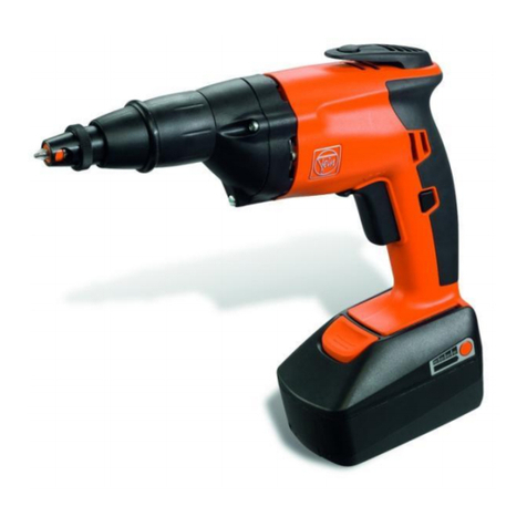
Fein ASse 636II-28bT Kinetik Setup guide

1 88 50 265 06 0 X 01.03 1
1 88 50 265 06 0 X 01.03 Printed in Germany - Imprimé en Allemagne, FEIN Stuttgart
Reparaturanleitung
Repair Instructions
Instructions de réparation
Elektro-Schrauber – umschaltbar für Rechts- und Linkslauf
Electric screwdriver –reversible for forward and reverse action
Visseuse électrique – pour marche à droite /à gauche
Technische Änderungen vorbehalten/Subject to technical modifications/Caractéristiques techniques sous réserve de modifications.
7 210 88/ASse 636II-28b Kinetik

21 88 50 265 06 0 X 01.03
D7 210 88/ASse 636II-28 bT
2.2.1 Wartungsintervalle:
Nach ca. 300 Betriebsstunden:
2.2.2 Maschine reinigen. Bürstenhalter und Isolierteile aus-
blasen oder auspinseln.
2.2.3 Getriebefett erneuern. Bitte verwenden Sie nur FEIN
Spezialfett nach Tabelle Seite 4.
Je nach Einsatzart und Einsatzdauer, spätestens jedoch
nach 6 Monaten:
2.2.4 Maschine gründlich reinigen. Kugellager und Getriebe
mit Reinigungsmittel auswaschen und mit neuem Fett
versorgen (siehe Seite 4).
Achtung: Elektrische Teile nur trocken reinigen!
Schäden, die durch unsachgemäße Behandlung, Überlastung
oder normale Abnutzung entstanden sind, bleiben von der
Garantie ausgeschlossen.
Für Schäden, die durch Material- oder Herstellfehler entstan-
den sind, übernehmen wir die Gewährleistung.
2.3 Kohlebürstenwechsel
Die Kohlebürsten sind durch neue zu ersetzen, wenn
sie sich bis auf 7 mm Länge abgenützt haben.
Beim Nachprüfen der Kohlebürsten muss darauf
geachtet werden, dass sie wieder in gleicher Stellung
eingesetzt werden und sich im Bürstenhalter leicht
bewegen lassen.
Nur Original FEIN Kohlebürsten
verwenden! Neue Kohlebürsten zuerst 15 Minuten
unbelastet einlaufen lassen.
3. Demontage der Maschine
●Netzstecker ziehen!
●Einsatzwerkzeug entfernen.
3.1 Schraube (230) lösen, Schaltdrücker (220) abziehen.
3.2
Linsensenkschraube (250) und die Linsenblechschraube
(240) lösen, dann Handgriff-Deckel (200) abnehmen.
3.3 Anschlusskabel (160) bzw. Verbindungsleiter vom
Schalter (20) und Umschalter (40) lösen, dann die
Schalter (20, 40) herausziehen.
3.4 Nach Lösen der Schrauben (100) Bürstenhalter (50)
und Störschutzkondensator (30) herausnehmen.
Anschlüsse nach Schaltschema.
3.5 Zylinderschrauben (450,460) lösen und äußeres Lager
(350) mit Zwischenlager (500) abnehmen und
zerlegen.
3.6 Anker (301) herausziehen.
3.7 Isolierring (140) aus dem Motorgehäuse (10) ziehen,
Zylinderschrauben (130) lösen, Polgehäuse (120) und
Ringe (121) herausnehmen.
1. Technische Daten
Bestellnummer 7 210 88
Bauart ASse 636II-28bT Kinetik
Nennaufnahme 450 W
Leistungsabgabe 260 W
Stromart 1 ~
Lastdrehzahl 0-2700/min
Leerlaufdrehzahl 0-3800/min
Max. Anziehdrehmoment
bei hartem Schraubfall 12 Nm
Gewicht 1,4 kg
Schutzklasse II q
Schrauben Ø 6,3 mm
Werkzeugaufnahme Innenflachkant
DIN 3126-H7
2. Wartung
Bitte beachten Sie, dass Elektrowerkzeuge grundsätzlich nur
durch Elektrofachkräfte repariert, gewartet und geprüft werden
dürfen, da durch unsachgemäße Reparaturen erhebliche
Gefährdungen für den Benutzer entstehen können (BGV A2).
Wiederholungsprüfungen sind nach DIN VDE 0702-1 durch-
zuführen. Nach Reparaturen sind die Vorschriften nach
DIN VDE 0701 Teil 1 / 9.00 zu beachten.
Nur Original FEIN-Ersatzteile verwenden!
Sicherheitshinweise 3 41 30 054 06 1 durchlesen!
Bei Inbetriebsetzung, beim Arbeiten und bei der Wartung der
Maschine sind die einschlägigen Unfallverhütungsvorschriften
der Berufsgenossenschaften zu beachten.
Für die bestimmungsgemäße Verwendung gilt das Gesetz über
technische Arbeitsmittel (Gerätesicherheitsgesetz).
2.1 Elektrische Funktionsprüfung
●Prüfung des Motors mit Elektronik:
Wenn keine Funktion, dann Prüfung des Motors
ohne elektronischen Drehzahlsteller, dabei
Prüfspannung entsprechend der Nennspannung an
den Motorzuleitungen anschließen.
2.2 Allgemeine Wartungsarbeiten:
●Anschlussleitung (160) auf Beschädigungen kontrol-
lieren!
●Motor mit trockener Druckluft ausblasen.
●Kohlebürsten überprüfen (siehe Abschnitt 2.3).

1 88 50 265 06 0 X 01.03 3
D
4. Montage der Maschine
7 210 88/ASse 636II-28 bT
Der Zusammenbau erfolgt sinngemäß in umgekehrter Reihen-
folge.
Vorhandene Beilegeringe wieder an den richtigen Stellen
einbauen. Ihr Verlust kann zu Beschädigungen führen.
Der im Getriebekopf befindliche Nockenring (390) ist so
einzubauen, dass formgleiche Nocken gegeneinander liegen.
Ist der mit dem Stirnrad (370) in Eingriff stehende Nockenring
(390) abgenützt, kann ein Austausch dadurch umgangen
werden, dass der identisch aufgepresste Nockenring gegen
den verschlissenen Nockenring getauscht wird.
Die Nocken am Stirnrad können durch stirnseitiges
Abschleifen wieder zu einer scharfkantigen Form gebracht
werden.
Bei der Montage sind folgende Punkte besonders zu beachten:
Werkzeugträger vormontiert, d.h. 2. Nockenring so aufge-
steckt, dass Verzahnung fluchtend bei Anlage, Kupplungsring
(395) mit langer Bundseite und darauf aufgesteckter Scheibe
(396) in Richtung Maschinenspitze aufgeschoben.
Abschließende Prüfung nach Punkt 2.

41 88 50 265 06 0 X 01.03
Anschlussplan
Connecting plan
Schéma des connexions
7 210 88/ASse 636II-28 bT
Fettmengen und Fettarten
Types and quantities of grease
Types et quantités de graisse
UKW-Drossel nur von 121…250 V
inductor only 121…250 V
bobine de réactance seulement de 121…250 V
Netz
Net
Réseau
Fettart
Type of grease
Type de graisse
0 40 121 0300 4
0 40 121 0300 4
für Axial-Nadelkäfig Teil 365
for thrust needle cage
part 365
pour cage de butée à
aiguilles pièce 365
Tuben-Inhalt
Contents of tube
Contenu de tube
85 g
Bestellnummer
Order Reference
Référence
3 21 60 003 21 7
Fettmenge
Quantity
Quantité
Für Getriebe:/for gears:/pour engrenages:
10 g

1 88 50 265 06 0 X 01.03 5
7 210 88/ASse 636II-28 bT
M = 0,8…1 Nm
M = 0,9…1,1 Nm
M = 0,9…1,1 Nm
mit Loctite Nr. 242 gesichert
protected with "Loctite No. 242"
protégée avec «Loctite No. 242»
M = 10…12 Nm
mit Loctite 573 abgedichtet
closed with "Loctite 573"
rendu étanche avec «Loctite 573»
abgesetzte Nocken gegenüberliegend
stepped cams are facing each other
cames échelonnées sont l'un vis-à-vis de l'autre
Außenverzahnung muss fluchten
external teeth must be aligned
denture extérieure doit être en alignement
mit Loctite Nr. 242 gesichert
protected with "Loctite No. 242"
protégée avec «Loctite No. 242»
M = 1,0…1,4 Nm
UKW-Drosseln
inductors
bobinés de réactance
b-Anschluß ohne Pos. 101
b-Connection without Pos. 101
b-Connexion sans Pos. 101
X

61 88 50 265 06 0 X 01.03
7 210 88/ASse 636 II-28b Kinetik
480
470
350
430
420
640
590
596
595
620
630
610
400
390 382
380
382396 395 385 370 375
365378
500
121
130
320 330 301
330
140 120
355
10
410
230
220
450
460
A
B
B
A
7 210 88/ASse 636II-28 bT
410
415
570
GB, AU, CA
M = 10…12 Nm
mit Loctite Nr. 242 gesichert
protected with "Loctite No. 242"
protégée avec «Loctite No. 242»
mit Loctite Nr. 242 gesichert
protected with "Loctite No. 242"
protégée avec «Loctite No. 242»
M = 1…1,4 Nm
mit Loctite 573 abgedichtet
closed with "Loctite 573"
rendu étanche avec «Loctite 573»
abgesetzte Nocken gegenüberliegend
stepped cams are facing each other
cames échelonnées sont l'un vis-à-vis de l'autre
Außenverzahnung muss fluchten
external teeth must be aligned
denture extérieure doit être en alignement
400

1 88 50 265 06 0 X 01.03 7
100
250
200
240
260
270
180
160
170
190
40
50 90
80
30
101
20
A
N 06/ AU
163
N 08/ CH
164
N 24/ GB
162
N 24/ GB
161
165
N 09/ CA
7 210 88/ASse 636II-28 bT
Anzahl
Quantity
Quantité
Teil-Nr. Bestellnummer
Part.No. Order Reference
No. Référence
10 3 19 01 117 02 1 1
20 3 07 01 234 00 2 (110 V) 1
3 07 01 228 00 2 (220-240 V) 1
30 3 07 22 179 01 0 1
40 3 07 01 238 00 1 1
50 3 07 12 043 00 1 2
80 3 07 11 059 00 7 2
90 3 07 13 010 00 9 2
100 4 30 02 014 99 8 4
101 4 24 43 002 99 2 3
120 5 1 274 001 11 2 (110-120 V) 1
5 1 274 001 23 8 (220-240 V) 1
121 3 26 01 267 00 6 2
130 4 30 02 024 99 7 2
140 3 14 28 122 00 5 1
160 3 07 07 263 01 9 (110-240 V) 1
161 3 07 07 349 01 8 (230 V, GB) 1
162 3 07 07 378 01 1 (110 V, GB) 1
163 3 07 07 358 01 3 (240 V, AU) 1
164 3 07 07 351 01 9 (230 V, CH) 1
165 3 07 07 097 01 0 (120 V, 60 Hz,CA) 1
170 3 14 13 142 00 9 1
180 3 24 31 021 00 7 1
190 4 30 46 002 00 5 2
200 3 12 01 066 00 5 1
220 3 28 05 120 00 0 1
230 4 30 66 006 03 2 1
240 4 30 46 024 00 5 1
250 4 30 66 002 99 2 1
260 3 07 64 065 01 0 (121-250 V) 2
260 3 07 19 117 01 4 (110 V) 1
270 3 07 19 118 01 2 (110 V) 1
301 5 3 274 001 11 4 (110 V) (Z=5) 1
5 3 274 001 23 0 (220-240 V) (Z=5) 1
320 3 26 12 084 00 1 1
330 4 17 01 001 17 2 2
350 3 15 08 235 00 3 1
355 4 17 09 040 00 5 3
365 4 17 15 041 00 9 1
370 3 36 57 161 00 7 (Z = 43) 1
375 4 17 19 027 00 1 1
378 4 17 19 026 00 7 1
380 3 09 01 139 00 7 1
382 3 26 24 094 03 2 2
385 3 09 01 339 00 9 1
390 3 01 02 101 01 3 1
(1 Paar/pair of /paire de)
395 3 01 01 037 00 4 1
396 3 24 08 375 00 2 1
400 3 01 04 110 01 1 1
3 01 04 112 00 4 (GB, AU, CA) 1
410 4 06 12 112 00 7 1
3 09 06 025 00 8 (GB, AU, CA) 1
415 4 17 08 014 00 1 (GB, AU, CA) 1
420 3 16 03 014 00 4 1
430 4 06 12 093 00 4 1
450 4 30 02 021 99 2 2
460 4 30 02 024 99 7 2
470 4 24 43 002 99 2 4
480 3 02 32 038 00 1 1
500 3 15 06 307 02 6 1
595 3 21 27 057 01 7 1
3 21 27 057 03 9 (GB) 1
596 3 05 05 061 02 9 1
590 3 05 05 061 00 4 1
610 3 21 27 057 00 8 1
3 21 27 039 01 1 (AU, CA) 1
3 21 27 021 04 2 (GB) 1
620 4 17 08 019 00 4 2
630 4 06 12 071 00 9 1
640 4 06 12 068 00 4 1
M = 0,8…1 Nm

81 88 50 265 06 0 X 01.03
7 210 88/ASse 636II-28 bT
Einzelteile Component Parts Pièces détachées
Teil-Nr. Bestellnummer
Part.No. Order Reference Benennung Description Désignation
No. Référence
10 3 19 01 117 02 1 1 Motorgehäuse motor housing carter moteur
20 3 07 01 234 00 2 1 elektronischer Drehzahlsteller, electronic speed control, régulateur de vitesse électronique,
110 V 110 V 110 V
3 07 01 228 00 2 1 elektronischer Drehzahlsteller, electronic speed control, régulateur de vitesse électronique,
220-240 V 220-240 V 220-240 V
30 3 07 22 179 01 0 1 Kondensator capacitor condensateur
40 3 07 01 238 00 1 1 Umschalter reversing switch renverseur
50 3 07 12 043 00 1 2 Bürstenhaltergehäuse carbon holder housing carter porte-balais
80 3 07 11 059 00 7 2 Kohlebürste carbon brush balais-charbon
90 3 07 13 010 00 9 2 Bürstenhalterkappe cover for carbon holder couvercle porte-balais
100 4 30 02 014 99 8 4 Zylinderschraube fillister head screw vis cylindrique
101 4 24 43 002 99 2 3 Sicherungsscheibe securing disc rondelle frein
120 5 1 274 001 11 2 1 Polpaket mit Wicklung, 110 V pole housing with winding, 110 V stator bobiné, 110 V
5 1 274 001 23 8 1 Polpaket mit Wicklung, pole housing with winding, stator bobiné,
220-240 V 220-240 V 220-240 V
121 3 26 01 267 00 6 2 Ring ring anneau
130 4 30 02 024 99 7 2 Zylinderschraube fillister head screw vis cylindrique
140 3 14 28 122 00 5 1 Isolierring insulating ring bague isolante
160 3 07 07 263 01 9 1 zus.ges. Kabel, 110-240 V cable, ass., 110-240 V ens. câble, 110-240 V
161 3 07 07 349 01 8 1 zus.ges. Kabel, 230 V, GB cable, ass., 230 V, GB ens. câble, 230 V, GB
162 3 07 07 378 01 1 1 zus.ges. Kabel, 110 V, GB cable, ass., 110 V, GB ens. câble, 110 V, GB
163 3 07 07 358 01 3 1 zus.ges. Kabel, 240 V, AU cable, ass., 240 V, AU ens. câble, 240 V, AU
164 3 07 07 351 01 9 1 zus.ges. Kabel, 230 V, CH cable, ass., 230 V, CH ens. câble, 230 V, CH
165 3 07 07 097 01 0 1 zus.ges. Kabel, 120 V, 60 Hz cable, ass., 120 V, 60 Hz ens. câble, 120 V, 60 Hz
170 3 14 13 142 00 9 1 Kabelschutzschlauch cable protecting sleeve gaine protectrice
180 3 24 31 021 00 7 1 Kabelklemmstück cable clamping bridge serre-câble
190 4 30 46 002 00 5 2 Linsenblechschraube pan-head tapping screw vis à tôle avec tête bombée
200 3 12 01 066 00 5 1 Deckel cover couvercle
220 3 28 05 120 00 0 1 Schaltdrücker switch trigger gâchette de l´interrupteur
230 4 30 66 006 03 2 1 Linsensenkschraube raised countersunk head screw vis à tête conique bombée
240 4 30 46 024 00 5 1 Linsenblechschraube pan-head tapping screw vis à tôle avec tête bombée
250 4 30 66 002 99 2 1 Linsensenkschraube raised countersunk head screw vis à tête conique bombée
260 3 07 64 065 01 0 2 Ringkerndrossel, 121-250 V inductor, 121-250 V bobine de réactance, 121-250 V
260 3 07 19 117 01 4 1 Verbindungskabel, 110 V connection cable, 110 V câble de connexion, 110 V
270 3 07 19 118 01 2 1 Verbindungskabel, 110 V connection cable, 110 V câble de connexion, 110 V
301 5 3 274 001 11 4 1 Anker kpl. mit Wicklung, 110 V armature with winding, 110 V induit bobiné, complet, 110 V
5 3 274 001 23 0 1 Anker kpl. mit Wicklung, armature with winding, induit bobiné, complet,
220-240 V 220-240 V 220-240 V
jeweils 5 Zähne 5 teeth for each armature 5 dents pour chaque induit
320 3 26 12 084 00 1 1 Dichtungsring sealing ring rondelle d'étanchéité
330 4 17 01 001 17 2 2 Rillenkugellager grooved ball bearing roulement à billes rainuré
350 3 15 08 235 00 3 1 äußeres Lager outer bearing palier extérieur
355 4 17 09 040 00 5 3 Lagernadel (Stift) pin tige
365 4 17 15 041 00 9 1 Axial Nadelkäfig thrust needle cage cage de butée à aiguilles
370 3 36 57 161 00 7 1 Stirnrad, 43 Zähne spur wheel, 43 teeth roue dentée droite, 43 dents
375 4 17 19 027 00 1 1 Wellenscheibe wave washer rondelle ondulée
378 4 17 19 026 00 7 1 Axialscheibe thrust disc disque de butée
380 3 09 01 139 00 7 1 Druckfeder pressure spring ressort de pression
382 3 26 24 094 03 2 2 Ausgleichscheibe compensating disc disque compensateur
385 3 09 01 339 00 9 1 Druckfeder pressure spring ressort de pression
390 3 01 02 101 01 3 2 Nockenring (1 Paar) cam ring (pair of) bague de came (paire de)
395 3 01 01 037 00 4 1 Kupplungsring clutch ring bague d'embrayage
396 3 24 08 375 00 2 1 Scheibe disc disque
400 3 01 04 110 01 1 1 zus.ges. Werkzeugträger tool holder, ass. ens. porte-outil
3 01 04 112 00 4 1 Werkzeugträger, GB, AU, CA tool holder, ass., GB, AU, CA ens. porte-outil, GB, AU, CA
410 4 06 12 112 00 7 1 Runddichtring sealing ring bague d'étanchéité
3 09 06 025 00 8 1 Haltering, GB, AU, CA retaining ring, GB, AU, CA bague de rentenue, GB, AU, CA
415 4 17 08 014 00 1 1 Kugel, GB, AU, CA ball, GB, AU, CA bille, GB, AU, CA
420 3 16 03 014 00 4 1 Lagerbuchse bearing bush coussinet
430 4 06 12 093 00 4 1 Runddichtring sealing ring bague d'étanchéité
450 4 30 02 021 99 2 2 Zylinderschraube fillister head screw vis cylindrique
460 4 30 02 024 99 7 2 Zylinderschraube fillister head screw vis cylindrique
470 4 24 43 002 99 2 4 Sicherungsscheibe securing disc rondelle frein
480 3 02 32 038 00 1 1 Klemmbügel clamp clip étrier de fixation
500 3 15 06 307 02 6 1 zus.ges. Zwischenlager intermediate bearing, assembled ensemble palier intermédiaire
595 3 21 27 057 01 7 1 zus.ges. Anschlaghülse end sleeve, assembled ens. butée de profondeur
3 21 27 057 03 9 1 zus.ges. Anschlaghülse, GB end sleeve, assembled, GB ens. butée de profondeur, GB
596 3 05 05 061 02 9 1 zus.ges. Überwurfhülse sleeve socket, ass. ens. corps de butée
590 3 05 05 061 00 4 1 Überwurfhülse sleeve socket corps de butée
610 3 21 27 057 00 8 1 Anschlaghülse sleeve douille
3 21 27 039 01 1 1 Anschlaghülse, AU, CA sleeve, AU, CA douille, AU, CA
3 21 27 021 04 2 1 Anschlaghülse, GB sleeve, GB douille, GB
620 4 17 08 019 00 4 2 Kugel ball bille
630 4 06 12 071 00 9 1 Runddichtring sealing ring bague d'étanchéité
640 4 06 12 068 00 4 1 Runddichtring sealing ring bague d'étanchéité
Listenmäßiges Zubehör Accessories as listed Accessoires suivant liste
6 01 10 210 01 9 1 Halter für Bit's (magnetisch) holder for bits (mag.) porte-outil pour embouts (mag.)
6 27 12 109 01 2 1 Einsatz für Kreuzschlitz- bit for Phillip's screws tournevis pour vis cruciformes
schrauben
1 88 50 265 06 0 X 01.03 9
G7 210 88/ASse 636II-28 bT
1. Technical Data
Order Reference 7 210 88
Type ASse 636II-28bT Kinetik
Input 450 W
Output 260 W
Current type 1 ~
Speed, full load 0-2700/R.P.M.
Speed, no load 0-3800/R.P.M.
Max. torque approx. hard base 12 Nm
Weight 1.4 kg
Safety Class II q
Self-drilling screws Ø 6.3 mm
Tool holder tool holding fixture
DIN 3126-H7
2. Maintenance
Please note that electrical tools should only be repaired, ser-
viced and checked by qualified electricians, since repairs car-
ried out improperly can place the user at serious risk
(BGV A2).
Check tests have to be carried out according to DIN VDE
0702-1.
After repair the regulations laid down in German
Industrial Standard DIN VDE 0701 Parts 1 / 9.00 must be
complied with.
Only use original FEIN spare parts! Please read safety
instructions No. 3 41 30 054 06 1 thoroughly!
The relevant German Industrial Insurers' accident prevention
regulations or equivalent must be complied with when starting
up, using and servicing the machine.
Correct usage of technical tools is as stipulated by the German
Technical Equipment Safety Act.
2.1 Electrical function test
●Testing the motor with electronics:
If the motor does not function, then it is tested
without electronics; a test voltage, corresponding to
the rated voltage, is connected to the motor supply
leads.
2.2 General maintenance:
●Check connection cable (160) for damage!
●Blow out the motor with dry compressed air.
●Check the carbon brushes (see section 2.3).
2.2.1 Maintenance intervals:
After approx. 300 operating hours:
2.2.2 Clean the machine. Blow out or brush out the brush
holders and insulating parts.
2.2.3 Replace gear lubricant. Please use only FEIN special
lubricant according to table page 4.
Depending on the type and duration of use, but at the
latest after 6 months of operation:
2.2.4 Clean the machine thoroughly. Wash out the ball
bearings and gear with a cleaning agent and add fresh
lubricant (see page 4).
Warning: Only dry clean electrical parts!
Damage to improper handling, overloading or normal wear
are excluded from the warranty. We assume warranty for
faulty material or craftsmanship.
2.3 Changing the carbon brushes
Replace the carbon brushes when they have worn
down to 7 mm.
When checking the carbon brushes, ensure that they
are re-inserted in the same position and that they move
freely in the brush holder.
Only use genuine FEIN carbon brushes!
Allow the new carbon brushes to run in for 15 minutes
without load.
3. Dismantling the machine
●Remove the power plug from the mains receptacle!
●Remove the bit.
3.1 Unscrew screw (230), pull off switch trigger (220).
3.2 Unscrew raised countersunk head screw (250) and
pan-head tapping screw (240), then take off handle
cover (200).
3.3 Remove connection cable/supply lead (160) from
switch (20) and reversing switch (40), then draw out
switches (20, 40).
3.4 After unscrewing screws (100) draw out carbon
holder (50) and capacitor (30). Connections according
to connecting plan.
3.5 Loosen fillister head screws (450, 460), remove outer
bearing (350) with intermediate bearing (500) and
take apart.
3.6 Pull out armature (301).
3.7 Draw insulation ring (140) out of motor housing (10),
unscrew fillister head screws (130), remove pole
housing (120) and rings (121).

10 1 88 50 265 06 0 X 01.03
G
4. Assembling the machine
7 210 88/ASse 636II-28 bT
Re-assemble in reverse sequence.
Please bear in mind that existing washers are to be placed in
the right places. Their loss would lead to damage.
The movable cam ring (390) for the gear head has to be
installed so that cams of the same form are facing each other.
When the cam ring (390), which is in mesh with spur wheel
(370), is worn replace it by mounting the cam ring next to it
and fitting the worn cam ring in its place.
The cams on the spur wheel can be edged again by regrinding
their faces.
When re-assembling the machine pay special attention to the
following points.
i.e. the 2nd cam ring be fitted in such a way that the toothing
of both cam rings is aligned when they sit close. Clutch ring
(395) must be slipped on with its long collar side and fitted
disc (396) pointing in the direction of the machine head.
Final check according to section 2.

1 88 50 265 06 0 X 01.03 11
F7 210 88/ASse 636II-28 bT
2.2.1 Intervalles d'entretien:
Au bout de 300 heures de service environ:
2.2.2 Nettoyer la machine. Nettoyer à l’air comprimé ou au
pinceau les supports de balais et les pièces isolantes.
2.2.3 Changer la graisse de l'engrenage. N’utiliser que de la
graisse spéciale FEIN suivant la table page 4.
En fonction du type et de la durée d'utilisation, mais au
plus tard après 6 mois:
2.2.4 Nettoyer la machine à fond. Laver les roulements à
billes et l'engrenage avec un produit nettoyant puis
remettre de la graisse neuve (voir page 4).
Attention: Nettoyer à sec seulement les pièces
conductrices de l'électricité!
Nous déclinons toute garantie pour dommages dus à un
traitement non convenable, surcharge ou usure normale.
Nous assumons la garantie pour des défauts de matière ou de
fabrication.
2.3 Changement des balais
Si les balais de charbon sont usés sur plus de 7 mm de
longueur, les remplacer par des balais neufs. Lors de la
vérification de l'état des balais, veiller à les remettre
chacun dans son logement correspondant et dans sa
position d'origine. Les balais doivent se mouvoir
aisément dans leur logement. N'utiliser que des balais
d'origine FEIN. Une fois les balais changés, faire
marcher la macine à vide pendant un quart d'heure.
3. Démontage de la machine
●Débrancher la fiche mâle de la prise de courant!
●Enlever l'embout.
3.1 Desserrer la vis (230), tirer la gâchette de
l'interrupteur (220).
3.2 Enlever la vis à tête conique bombée (250) et la vis
à tôle avec tête bombée (240), puis enlever le
couvercle de la poignée (200).
3.3 Déconnecter le câble/le conduit d'alimentation (160)
de l'interrupteur (20) et du renverseur (40), puis
enlever les deux interrupteurs (20,40).
3.4 Après avoir desserré les vis (100), enlever le porte-
balais (50) et le condensateur (30). Connexions selon
schéma des connexions.
3.5 Desserrer les vis cylindriques (450,460), enlever puis
démonter le palier extérieur (350) avec le palier
intermédiaire (500).
3.6 Sortir le rotor (301).
3.7 Sortir la bague isolante (140) du carter moteur (10),
enlever les vis cylindriques (130), sortir le stator (120)
et les anneaux (121).
1. Caractéristiques techniques
Référence 7 210 88
Modèle ASse 636II-28bT Kinetik
Puissance absorbée 450 W
Puissance utile 260 W
Nature du courant 1 ~
Vitesse en charge 0-2700/min
Vitesse à vide 0-3800/min
Couple max. en serrage fort 12 Nm
Poids 1,4 kg
Classe de protection II q
Vis autoperceuses Ø 6,3 mm
Porte-outil avec méplats
DIN 3126-H7
2. Entretien
Veuillez tenir compte du fait que les outils électriques ne
doivent être réparés, entretenus et contrôlés que par un
personnel spécialisé étant donné que des réparations
inadéquates peuvent représenter un risque considérable pour
l’utilisateur (BGV A2). Effectuer des contre-essais selon
DIN VDE 0702-1. Après des réparations il faut respecter à ce
titre les prescriptions selon DIN VDE 0701 1ère partie 9/00.
N'utiliser que des pièces de rechange d'origine FEIN!
Lire les consignes de sécurité 3 41 30 054 06 1 attentivement et
de bout en bout!
Lors de la mise en service, lors du travail et de l’entretien de la
machine, respecter les prescriptions pertinentes de prévention
des accidents édictées par les mutuelles d’assurances
professionnelles. L’utilisation de la machine conformément à sa
destination est régie en Allemagne par la loi sur les moyens de
travail techniques (loi sur la sécurité des appareils).
2.1 Vérification fonctionelle
●Vérification du moteur avec du matériel
électronique:
En l’absence de fonctionnement, vérifier le moteur
sans matériel électronique. La tension de
vérification doit coincider avec la tension nominale
sur les fils d’alimentation du moteur.
2.2 Opérations générales d'entretien:
●Vérifier si le câble d'alimentation (160) est
endommagé!
●Nettoyer le moteur à l'air comprimé sec.
●Vérifier l'état des balais (Cf. la section 2.3).

12 1 88 50 265 06 0 X 01.03
F
4. Remontage
7 210 88/ASse 636II-28 bT
Le remontage s'opère en sens inverse.
Veiller aux rondelles-cales. Leur absence peut entraîner des
endommagements.
La bague à came déplaçable (390) pour la tête d'engrenage doit
être installée de sorte que les cames de la même forme soient
l'un vis-à-vis de l'autre. Lorsque la bague à came (390), qui est
en prise avec la roue dentée (370), est usée, il faut la remplacer
par la bague à came fixée à côté et monter la bague à came
usée à sa place. Les cames sur la roue dentée peuvent être
ravivées en réaffûtant leurs fronts.
Lors du montage il faut particulièrement faire attention aux
points suivants:
Le porte-outil doit être prémonté, c'est-à-dire monter la
seconde came de manière à ce que la denture des deux cames
soit en alignement quand elles collent. Pousser la bague
d'engrenage (395) avec le collet long, et le disque (396) monté
orientés vers la tête de la machine.
Contrôle final comme indiqué à la section 2.
This manual suits for next models
1
Table of contents
Languages:
Other Fein Power Tools manuals

Fein
Fein AMM500 PLUS AS User manual

Fein
Fein ASs 648-1 User manual

Fein
Fein KBM 52 U User manual

Fein
Fein GRIT GXE Series User manual

Fein
Fein FMM350Q User manual

Fein
Fein AFMM 18 QSL User manual

Fein
Fein BLS1.6X User manual

Fein
Fein QSz 7 49 User manual

Fein
Fein FSC500QSL User manual

Fein
Fein ASM 9-2 User manual

Fein
Fein JHM Magforce User manual

Fein
Fein ASt638 User manual

Fein
Fein BLS 1.6 E User manual

Fein
Fein BLS 1.6 E User manual

Fein
Fein 7 229 43 User manual

Fein
Fein Slugger JMU 404 M User manual

Fein
Fein BLK1.3TE User manual

Fein
Fein AFMT12SL User manual

Fein
Fein FMM350Q User manual

Fein
Fein 7 230 26 Setup guide