Ferax FHF-1200 User manual

www.servotool.com 0710-01.2
GB Subjecttochange
DE Änderungenvorbehalten
CZ Změnyvyhrazeny
HU Változtatásjogátfenntartjuk
IT Conreservadimodifiche
RU Технические характеристики могут
вноситься измнения без
предварительного уведомления.
ES Reservadoelderechode
modificacionestécnicas
Art.no. 12604-0302
FHF-1200
GB
DE
CZ
HU
IT
RU
ES
USERS MANUAL 06
GEBRAUCHSANWEISUNG 16
NÁVOD K POUŽITÍ 26
HASZNÁLATI UTASÍTÁS 35
MANUALE UTILIZZATI 45
РУКОВОДСТВО ПО ЭКСПЛУАТАЦИИ
55
MANUAL DE INSTRUCCIONES 65

Ferax 79
Exploded view
02 Ferax
4
7
4
7
25
6
3
7
16
8
11
15
9
10
12
13
14
1
Fig.A1
Fig.A2

Ferax 0378 Ferax
Spare parts list
FeraxNo. Description Ref.No.
408940 Base plate with spring 6 + 7
302111 Adapter for dust extraction 8
408941 Carbon brushes (set) 64
408942 Parallel guide 88+87 (2x) +90 (4x)
408943 Guide rod (set) 91 + 93 + 89 (2x)
302133 Spannhülsenschlüssel 94
408944 Template guide 95
8
17 7
19
20
10
18
Fig. B
Fig. C

Ferax 7704 Ferax
22
923
22
9
24
22
Fig. D
Fig. E

Ferax 0576 Ferax
21
4
13 12
15
16
25
Richtig
Falsch
Fig. F
Fig. G Fig. H

Ferax 7506 Ferax
ROUTER
The numbers in the following text correspond with the pictures at page 2 - 5.
For your own safety and for the safety of others, please read these operating
instructions carefully before starting to work with this machine. This will
familiarize you more rapidly with the operation of this machine, and will prevent
unnecessary risks. Keep these operating instructions nearby in a safe location
and hand them over whenever there is a change of operator on the machine.
Intended usage
This top miller was designed for precision milling of wood and timber products in the DIY
sector and is also suitable for copy milling. It is not intended for any other form of use.
Contents
1. Technical specifications
2. Safety
instructions
3. Mounting accessoires
4. Operation
5. Maintenance
1. TECHNICAL SPECIFICATIONS
Package contents
1 Router
12 Cutters (router bits)
1 Parallel guide
1 Template guide
2Screws
2 Nuts
1Adapter for dust extraction
1 Dust tube
1 Wrench
2 Allen key
Voltage 230 V~
Frequency 50 Hz
Power input 1200 W
No load speed 9000 - 30000/min
Max. cutter diameter 30 mm
Cutting depth 40 mm
Collet 6 + 8 mm
Weight 4.5 kg
Lpa (sound pressure) 86 dB(A)
Lwa (sound power) 97 dB(A)
Vibration value 1.7 m/s2
GB

Ferax 07
1 6 mm Collet
1 8 mm Collet
1 Instruction manual
Check the machine, loose parts and accessories for transport damage.
Product information
Fig. A1+A2 and C (items 21-25: Figs. D-F)
1. On/off switch
2. Handle
3. Switch lock button
4. Handle adjustment switch
5. Adjusting wheel for electronic speed control
6. Clamping lever
7. Fixing screws for parallel fence
8. Collet nut
9. Base plate
10. Spindle lock
11. Depth stop revolver
12. Plunge depth adjustment button
13. Wing bolt for depth stop
14. Depth stop
15. Plunge depth scale
16. Plunge depth fine-tuning button
17. Parallel fence ruler
18. Zero mark
19. Parallel fence
20. Guide rod
21. Dust extraction facility
22. Screws
23. Template guide
24. Dust adapter
25. Dust tube
2. SAFETY INSTRUCTIONS
The following symbols are used in these instructions for use:
In accordance with essential applicable safety standards of European
directives.
Class II machine – Double insulation - You don’t need any earthed plug.
Denotes risk of personal injury, loss of life or damage to the tool in case of
non-observance of the instructions in this manual.
GB
74 Ferax
CE DECLARACIÓN DE CONFORMIDAD (ES)
Declaramos bajo nuestra exclusiva responsabilidad que este
FHF-1200
cumple con las siguientes normas o documentos normalizados:
EN60745-1, EN60745-2-17, EN55014-1, EN55014-2, EN61000-3-2, EN61000-3-3
de acuerdo con las normativas.
98/37/EC, 73/23/EEC, 89/336/EEC, 2002/95/EC, 2002/96/EC
del 01-08-2007
ZWOLLE NL
J.A. Bakker - van Ingen J. Lodewijk
CEO Quality Manager
Es nuestra política mejorar continuamente nuestros productos y por tanto nos reservamos
el derecho a cambiar las características del producto sin previo aviso.
Servotool B.V. • Lingenstraat 6 • 8028PM Zwolle • Holanda
ES

Ferax 73
Limpieza
Limpie periódicamente el alojamiento de la herramienta con un paño suave,
preferiblemente cada vez que la utilice. Mantenga las ranuras de ventilación sin polvo ni
suciedad. Si no puede retirar la suciedad, utilice un paño suave y agua jabonosa. No
emplee nunca disolventes como gasolina, alcohol, amoniaco, etc. Estos disolventes
pueden dañar las partes plásticas.
Lubricación
La máquina no requiere lubricación adicional.
Averías
Si ocurre algun desperfecto por motivo de desgaste de una pieza, diríjase al vendedor.
En la lista de piezas de repuesto que se encuentra adjunta aparte puede encontrar la
relacion de piezas que pueden ser encargadas.
Uso ecológico
Para prevenir los daños durante el transporte, el aparato ha sido embalado. Dicho
embalaje está hecho, en la medida de lo posible, de material reciclable. Le rogamos, por
lo tanto, que recicle dicho material.
Cualquier aparato eléctrico o electrónico desechado y/o defectuoso tiene que
depositarse en los lugares apropiados para ello.
• Se ha conectado la
herramienta pero el
motor no funciona
• La fresadora tupí va
muy lenta
• Fuerte vibración
• Chispas en el interior
de la carcasa
• La corriente está
interrumpida
• Hay cables sueltos en
el enchufe o en la caja
del enchufe
• El interruptor está
dañado
• La fresa está
desafilada o dañada
• Las revoluciones
variables son muy
bajas
• El motor presenta
sobrecarga
• El vástago de la fresa
está doblado
• Las escobillas de
carbón están
desgastadas
• Reparar la corriente
• Revisar o reparar el
enchufe y la caja del
enchufe
• Reparar el interruptor
• Afilar o cambiar la
fresa
• Aumentar las
revoluciones variables
• Reducir la presión
sobre la fresadora
tupín
• Cambiar la fresa
• Cambiar las escobillas
de carbón
ES
08 Ferax
Indicates electrical shock hazard.
Disconnect the mains power connector (i.e. isolate the system) whenever the
cable gets damaged, and also before starting any maintenance and/or
cleaning work.
Read instructions carefully
The number of revolution of the machine can be electronically set.
Wear ear and eye protection
Wear protective gloves
Faulty and/or discarded electrical or electronic apparatus have to be collected
at the appropriate recycling locations.
Additional safety instructions
• Please check workpieces for any obstructions on the surface of the material, such as
protruding nails etc., to protect the router head.
•Wait until the router has come to a complete stop before removing any blocked or
routed material around the cutter. Use a long stick for this and not your finger.
• Please keep your hands away from the routing surface.
• Immediately switch off the tool as soon as it starts producing any unusual noise or
starts vibrating excessively.
• Before every startup, always ensure that all parts are protected and that all tools have
been removed etc.
Electrical safety
Always check that the power supply corresponds to the voltage on the rating
plate.
Your machine is double insulated in accordance with EN 60745; therefore no
earthwire is required.
•Only use an approved extension cable suitable for the power input of the machine.
The minimum conductor size is 1.5 mm2.When using a cable reel always unwind the
reel completely.
GB

Ferax 09
3. MOUNTING ACCESSORIES
Prior to mounting an accessory always unplug the tool.
Wait until the machine has come to a complete standstill and the cutter has
cooled down before replacing a cutter.
Selection of milling tools
Awide range of different millers covering an equally wide range of construction types and
quality standards is available to suit various types of processing and applications:
Millers made of high-speed steel (HSS) are suitable for applications involving the
machining of soft materials such as soft timber and plastics.
Millers made of hard metal are specifically intended for the machining of hard and
abrasive materials, e.g. hardwood or aluminium.
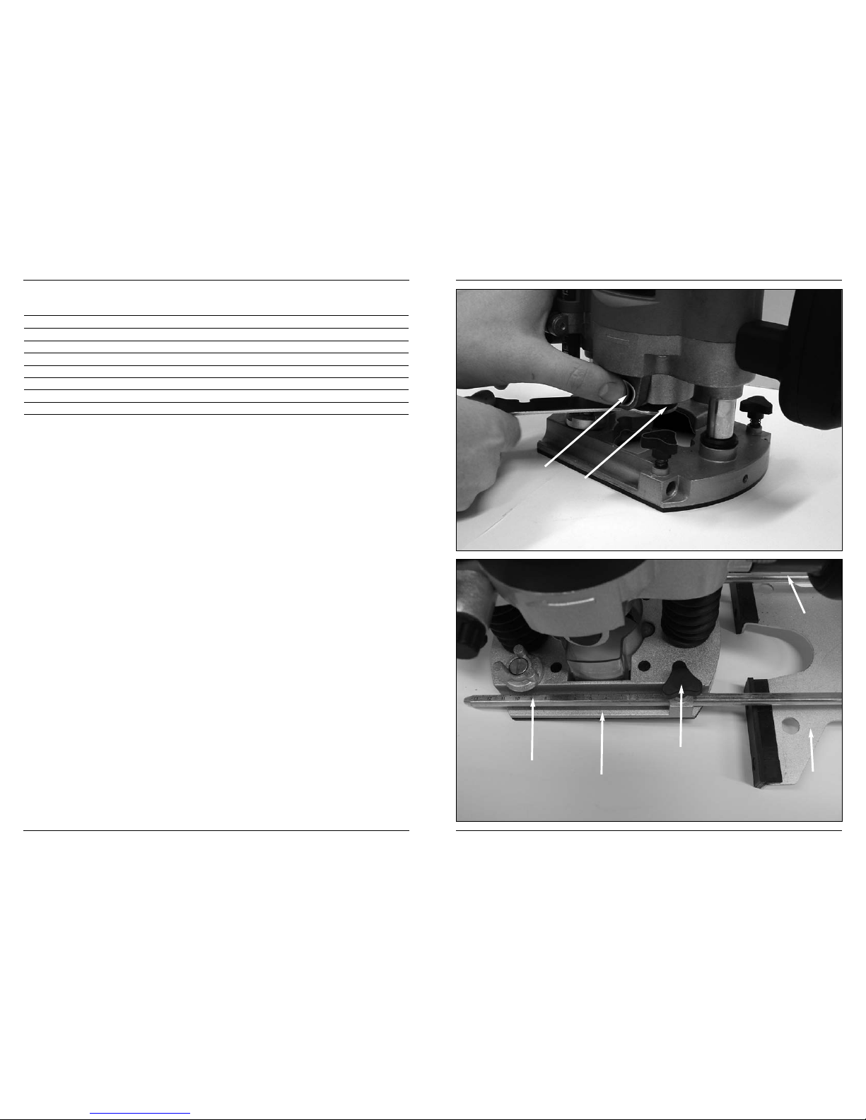
Mounting and removing cutters
Fig. B
Only use cutters with a shaft diameter which corresponds with the size of the collet. Only
use cutters which are suited for the maximum speed of the machine. The cutter diameter
should not exceed the maximum diameter (see ‘Technical specifications’). Never tighten
collet nut, if there is no router bit in collet; collet may be damaged.
Never apply pressure to the spindle inhibit when the motor is running! Failure
to comply with this instruction may damage the machine.
• Press down on the spindle interlock (10) and turn the nut on the collet nut (8) until it
locates in the interlock. Press and hold down the spindle interlock throughout this
operation.
•Open the nut on the collet nut (8) with the open-ended wrench by rotating it anti-
clockwise.
•Insert the shaft of the milling tool in the collet nut (i.e. chuck). The milling tool shaft
must be inserted to a depth of at least 20 mm.
• Tighten down the nut on the collet nut in a clockwise direction until the milling tool is
firmly secured.
• To replace the milling tool, unfasten the nut on the collet nut (8).
When the unit is supplied, the collet nut is mounted in the machine with a diameter setting
of 8 mm. To use milling tools with a shaft diameter of more than 6 mm, a different collet
nut can be fitted.
• To do this, turn the nut on the collet nut (8) anticlockwise until completely unfastened
then pull the collet nut out of the drive shaft.
• Install the 6 mm collet nut in the shaft and secure it by tightening down the nut (8).
GB
72 Ferax
Ajuste rápido
• Lea el valor de la escala (12).
• Extraiga los pernos de orejas (13) en el sentido contrario a las agujas del reloj.
• Gire hacia arriba el tope de profundidad con el botón regulador (12), y vuelva a leer
el valor de la escala. La diferencia entre ambos valores es la profundidad fijada de la
fresa.
Ejemplo: El valor de la escala (15) es de 2,5 en la posición cero. Después de girar el
botón regulador (12), el valor es de 1,5. La profundidad de la fresa se ha fijado por tanto
en 1,0 cm.
•Apriete los pernos de orejas (13) en el sentido de las agujas del reloj.
Ajuste de precisión:
• El botón micrométrico (16) en la parte superior sigue estando en cero. Gírelo por
completo una vez en el sentido de las agujas del reloj hasta que se vuelva a colocar
en la posición cero. La profundidad de la fresa se ha reducido ahora en 1,0 mm.
• Si fuera necesario, también es posible ajustar la profundidad de la fresa en 0,1 mm.
Ajuste mediante el tope de profundidad de revólver
El tope de profundidad de revólver (11) le permite elegir rápidamente entre tres
profundidades de corte distintas. Estas se determinan también ajustando el tope de
profundidad (14).
Para profundidades mayores se recomienda efectuar varios pases de fresado con
coeficientes de corte menores.
• Ajuste la profundidad de corte requerida girando el tope de profundidad de revólver
(11).
5. MANTENIMIENTO
Asegúrese de que la máquina no esté conectada cuando realice tareas de
mantenimiento en el motor.
Las máquinas están diseñadas para funcionar mucho tiempo con un mínimo de
mantenimiento. El funcionamiento satisfactorio depende del buen cuidado de la máquina
y de una limpieza frecuente.
Resolución de problemas
En la siguiente tabla encontrará algunas posibles causas de problemas y sus posibles
soluciones.
ES

Ferax 71
La velocidad requerida depende del material y puede determinarse haciendo una prueba
práctica. Además, las brocas de diámetro grande requieren una velocidad de rotación
menor.
Material Diámetro de la broca Posiciones de velocidad
Madera dura > 20 mm 1 - 2
10 - 20 mm 3 - 4
< 10 mm 5 - max
Madera blanda > 20 mm 1 - 3
10 - 20 mm 3 - 6
< 10 mm 5 - max
Aluminio > 15 mm 1
< 15 mm 1 - 2
Plástico > 15 mm 1 - 2
< 15 mm 2 - 3
Después de trabajar un largo período a baja velocidad, permita que la máquina se enfríe
haciéndola funcionar, por unos cuantos minutos, a alta velocidad.
Ajuste de altura de la columna de fresar
Fig. G
La palanca de fijación (6) se utiliza para establecer la altura máxima de la fresadora.
La profundidad de corte se define después. Habitualmente, esto es necesario cuando se
utiliza la herramienta en una mesa especial de fresado.
La fresadora se puede bajar contra la presión del muelle.
Bloquee la columna de fresar mediante la palanca de fijación.
Se fijará la fresadora y no volverá a su posición original.
Ajuste de la profundidad de fresado
Fig. G
La profundidad de fresado se ajusta con los botones 6, 12, 13 y 16. Si la profundidad de
fresado está ajustada correctamente, se puede fresar la hendidura deseada con una
precisión de 0,1 mm.
Preparación:
•Coloque la fresa deseada en la herramienta. La fresadora se puede bajar contra la
presión del muelle.
• Empuje la herramienta hacia abajo hasta que la fresa entre en contacto con la pieza,
y después fíjela con la palanca de fijación.
• Extraiga los pernos de orejas (13) en el sentido contrario a las agujas del reloj.
• Gire el botón (16) hasta la posición “0”.
• Utilice el botón (12) para fijar la profundidad hasta el fondo.
• Apriete los pernos de orejas (13) en el sentido de las agujas del reloj. La profundidad
de la fresa se ha fijado ahora en, exactamente, 0 mm.
ES
10 Ferax
Adjusting the parallel fence ruler
Fig. C
The parallel fence is a useful tool for precision routing at a fixed distance from the edge of
the workpiece.
• Install the correct miller in the tool.
• Slide the parallel fence (19) with guide rods (20) into the baseplate (9) and tighten it
down into the desired position using the fixing screws (7).
Mounting the template guide
Fig. D
The template guide is a handy aid for cutting a pattern.
•Mount the template guide (23) on the router base (9) using the screws (22).
• The template to be copied is located under the material being machined.
Set the milling depth so that the miller makes contact with the material being
machined but cannot come into contact with the template.
•Using the template guide, run along the contour of the template to create a copied
workpiece. Please note that, depending on the diameter of the milling tool, some
degree of dimensional variance can occur between template and workpiece.
Mounting the adapter for dust extraction
Fig. E + F
Inhaling sawdust is a health hazard. Use the adapter to extract all dust
generated during this operation and/or wear a facemask.
Use the dust adapter for the extraction of dust.
•Mount the dust adapter (24, Fig. E) with the screws (22) on the cutter sole (9).
•Place the dust tube (25) in the dust extraction facility (21, Fig. F).
• Place the tube of your vacuum cleaner on the dust tube (25, Fig. F).
Keep the outlet of the machine behind the machine for a good view on the
workpiece.
4. OPERATION
Adjustable handles
Fig. A1
To simplify operation, the handles (2) can be adjusted individually. The adjustment angle
is between 0 and 60 degrees in three different positions.
GB

Ferax 11
• Actuate the interlock to adjust the handle setting (4) and set the handle to the desired
angle.
• If you are unable to obtain your desired handle angle setting, release the interlock.
The handle will then lock into its new position.
The On/Off switch
Fig. A1
• To switch on the machine, press the On/Off switch (1) and keep them held down.
•Whenever you release the On/Off switch (1), the machine switches off.
• You can lock the On/Off switch in position by first pressing the On/Off switch (1), then
pressing the switch lock button (3). The switch rlock is released by a quick press on
the On/Off switch (1).
• Never put down the machine while the motor is still running. Never place the machine
on a dusty surface. Otherwise, particles of dust may get inside the machine.
Operation
• When switching on the machine, always wait until the motor reaches full speed before
starting to machine a workpiece.
• Clamp the workpiece and make sure that the workpiece cannot slide from under the
machine during the cutting activities.
•Hold the machine firmly and move it evenly over the workpiece. Do not force the
machine.
• Only use cutters which do not show any signs of wear. Worn cutters have a negative
effect on the efficiency of the machine.
• Always switch off the machine first before removing the plug from the wall socket.
• Milling must always take place in an opposing direction to the direction of rotation of
the miller. If you operate the tool in a synchronous direction to the rotational direction
of the miller, there is a serious risk of the tool being pulled out of your hands (see Fig.
H).
Speed preselection
Fig. A1
The required speed can be preselected with the adjusting wheel (5). Also during running
the rotational speed can be adjusted.
1 - 2 = low speed
3 - 4 = medium speed
5 - 6 = high speed
Max = maximum speed
GB
70 Ferax
4. FUNCIONAMIENTO
Mangos ajustables
Fig. A1
Para simplificar el manejo puede ajustar de forma individual los manubrios (2). El ángulo
de colocación se sitúa entre 0 y 60 grados, en tres posiciones diferentes.
•Utilice el regulador para la posición de los manubrios (4) para encontrar el ángulo de
agarre deseado.
• Una vez fijado el ángulo deseado, suelte el regulador. De este modo quedan fijados
los manubrios en la nueva posición.
El interruptor de Encendido/Apagado
Fig. A1
• Para encender la máquina pulse el interruptor conectador-desconectador (1) y
manténgalo apretado.
•Si suelta este interruptor, la máquina se apagará.
• Puede bloquearlo apretando primero el interruptor conectador-desconectador (1) y
seguidamente el botón de bloqueo (3). Pulsando brevemente el conectador-
desconectador (1) se volverá a liberar el bloqueo.
• No guarde la máquina con el motor encendido. No guarde la máquina sobre una
superficie polvorienta. Podrían entrar partículas de polvo en su interior.
Funcionamiento
• Una vez encendida la máquina, espere hasta que alcance su máxima velocidad de
giro antes de trabajar la pieza.
• Inmovilice la pieza de trabajo y verifique que no pueda deslizarse por debajo de la
máquina durante las actividades de cortado.
•Sostenga la máquina firmemente y muévala uniformemente sobre la pieza de trabajo.
No fuerce la herramienta.
• Utilice sólo fresas que no tengan signos de desgaste. Las fresas gastadas tienen un
efecto negativo en la eficacia de la máquina.
• Apague la máquina antes de retirar el enchufe de la toma de pared.
•El fresado se debe realizar siempre en contra de avance, es decir, en el sentido
contrario de la fresadora. Si el fresado se realizase en el mismo sentido que el de la
fresadora, existiría el peligro de que la máquina se le escapase de las manos al
operario (véase Fig. H)
Preselección de la velocidad
Fig. A1
La velocidad requerida se puede seleccionar anticipadamente mediante la ruedecilla (5).
La velocidad de rotación puede ajustarse aún estando en funcionamiento el aparato.
1 - 2 = baja velocidad
3 - 4 = velocidad media
5 - 6 = alta velocidad
Máx. = velocidad máxima
ES

Ferax 69
• Para ello desatornille por completo la tuerca tensora de sujeción (8) en el sentido
contrario a las agujas del reloj y saque todo el manguito adaptador del árbol motor.
• Coloque un manguito adaptador de 6 mm en el árbol, y fíjelo con la tuerca tensora de
sujeción (8).
Ajuste de la regla del tope paralelo
Fig. C
El tope paralelo es una herramienta útil para los fresados de precisión a distancia fija
desde el borde de la pieza.
•Coloque la fresa necesaria en la herramienta.
• Deslice el tope paralelo (19) a lo largo de las barras de guía (20) en la placa de
montaje (9), y fíjelo en la posición deseada con los pernos de orejas (7).
Montaje del casquillo guía
Fig. D
El casquillo guía es una ayuda práctica para el corte de diseños y patrones.
•Monte el casquillo guía (23) en el soporte de la fresadora (9) con los tornillos (22).
• El patrón a copiar se coloca bajo el material a trabajar. Ajuste la profundidad de la
fresa de modo que la fresa llegue al material a trabajar, pero no al patrón.
• Con ayuda de la guía patrón pase por el borde del patrón y cree de este modo una
pieza copiada. Tenga presente que en función del diámetro de la fresa se puede
producir una desviación del tamaño entre el patrón y la pieza.
Montaje del adaptador de serrín
Fig. E + F
Utilice el adaptador para el polvo para la extracción del polvo.
Es peligroso para la salud inhalar polvo de madera. Utilice el adaptador de
absorción de polvo y/o una protección pertinente de la respiración.
• Instale el adaptador para el polvo (24, Fig. E) con los tornillos (22) en la base de la
cortadora (9).
•Coloque el tubo para el polvo (25) en la salida para el polvo (21, Fig. F).
• Ponga el tubo de su aspiradora en el tubo para el polvo (25, Fig. F)
La salida del extractor debe colocarse por detrás de la má-quina para ver
correctamente la pieza de trabajo.
ES
12 Ferax
The required speed depends of the material and can be determined by practical testing.
Furthermore router bits with a large diameter need a lower rotational speed.
Material Diameter router bit Speed stages
Hardwood > 20 mm 1 - 2
10 - 20 mm 3 - 4
< 10 mm 5 - max
Softwood > 20 mm 1 - 3
10 - 20 mm 3 - 6
< 10 mm 5 - max
Aluminium > 15 mm 1
< 15 mm 1 - 2
Plastic > 15 mm 1 - 2
< 15 mm 2 - 3
After longer periods of working at low speed, allow the machine to cool down by running it
for a few minutes at high speed with no load.
Height setting of the router column
Fig. G
The clamping lever (6) is used to set the maximum height of the router.
The plunge depth is then fixed. This is usually necessary when using the tool on a special
router table.
The router can then be pushed down against the spring force.
Lock the router column using the clamping lever
The router is now locked and will no longer return to its original position.
Setting the plunge depth
Fig. G
The plunge depth can be adjusted by using buttons 6, 12, 13 and 16. If the plunge depth
is set correctly, the groove in question can be routed accurately to within 0.1 mm.
Preparation:
•Place the desired cutter in the tool. The router can be pushed down against the
spring force.
• Push the tool down until the cutter touches the workpiece, then lock it using the
clamping lever (11).
• Unfasten the wing bolt (13) by turning it anticlockwise.
• Set button (16) to zero.
• Use button (12) to set the depth all the way down.
• Tighten the wing bolt (13) by turning it clockwise. The milling depth is now set
precisely to 0 mm.
Rough setting:
• Read the value from the scale (15).
GB

Ferax 13
• Unfasten the wing bolt (13) by turning it anticlockwise.
• Turn the depth gauge upwards using the adjusting knob (12) and read off the value
again from the scale. The difference between the two values corresponds to the miller
depth setting.
Example: The value on the scale (15) corresponds to a datum setting of 2.5. After turning
the adjusting button (12), this value changes to 1.5. Accordingly, the miller depth setting is
now 1.0 cm.
• Tighten the wing bolt (13) by turning it clockwise.
Fine adjustment:
• The precision adjustment button (16) on the top of the unit is always set to zero. Turn
this button clockwise once only through 360° until it returns to its zero setting. The
milling depth is now reduced by 0.1 mm.
• If required, the milling depth can be set precisely to the nearest 0.1 of a millimetre.
Adjustment using the revolver- depth stop
The depth stop revolver (11) enables you to quickly choose between three different cutting
depths. These are also determined by the adjustment of the depth stop (14).
For larger routing depths, it is recommended to carry out several repetitive cuts with lower
removal rates.
• Adjust the required cutting depth by rotating the depth stop revolver (11).
5. MAINTENANCE
Make sure that the machine is not live when carrying out maintenance work on
the motor.
The machines have been designed to operate over a long period of time with a minimum
of maintenance. Continuous satisfactory operation depends upon proper machine care
and regular cleaning.
Troubleshooting
The following table contains a few possible causes of defect, together with proposed
solutions.
GB
68 Ferax
•Utilice sólo un cable de prolongación aprobado que sea adecuado para la potencia
de esta máquina. El tamaño mínimo del conductor es 1,5 mm2.Si utiliza un carrete
de cable, desenrolle siempre el carrete completamente.
3. ACCESORIOS DE MONTAJE
Antes de montar un accesorio desenchufe siempre la herra-mienta.
Espere hasta que la máquina esté completamente parada y la fresadora se
haya enfriado antes de reemplazar la fresa.
Selección de la fresa
Según la clase de tratamiento y aplicación existen diferentes fresas de diverso diseño y
calidad: las fresas de acero rápido (High Speed Steel, HSS) son adecuadas para los
trabajos de materiales blandos, como madera blanda y material sintético. Las fresas de
metal duro son especialmente adecuadas para el tratamiento de materiales más duros y
con mayor capacidad de desgaste sobre la herramienta, como la madera dura o el
aluminio.
Montaje y desinstalación de fresas
Fig. B
Utilice sólo fresas con un diámetro del eje que corresponda al tamaño de la pinza. Utilice
unas adecuadas para la velocidad máxima de la máquina. El diámetro de la fresa no
debe ser superior al diámetro máximo (consulte los ‘Datos técnicos'). No apriete nunca la
tuerca del mandril sin la fresa, puesto que puede dañar la tuerca.
¡No pulse nunca el bloqueador de husillo con el motor encendido! De lo
contrario podría dañarse la máquina.
• Pulse el regulador de husillo (10) y gire la tuerca tensora de sujeción (8) hasta que
llegue al regulador. Mantenga apretado el regulador de husillo durante este proceso.
•Abra la tuerca tensora de sujeción (8) con la llave de boca girando en dirección
contraria a las agujas del reloj.
• Coloque el vástago de la fresa en el manguito adaptador. El vástago de la fresa se
deberá introducir un mínimo de 20 mm.
• Apriete la tuerca tensora de sujeción en el sentido de las agujas del reloj hasta que la
fresa esté correctamente fijada.
• Para cambiar la fresa, abra la tuerca tensora de sujeción (8).
Cuando se suministra la máquina, el manguito adaptador está montado con un diámetro
de 8 mm. Para la utilización de fresas con un diámetro de 6 mm es posible cambiar el
manguito adaptador.
ES

Ferax 67
Herramienta de tipo II – Doble aislamiento – No requiere enchufe con
conexión a tierra.
Indica peligro de accidente, de muerte o riesgo de provocar averías en el
aparato en caso de no seguir las instrucciones de este manual.
Indica el peligro de sufrir descargas eléctricas.
Desconectar el enchufe en caso de que se dañe el cable, así como para los
trabajos de mantenimiento y limpieza.
Lea las instrucciones atentamente
Se puede establecer el número de revoluciones de la máquina de forma
electrónica.
Lleve protectores para los ojos y los oídos.
Llevar guantes de protección.
Cualquier aparato eléctrico o electrónico desechado y/o defectuoso tiene que
depositarse en los lugares apropiados para ello.
Instrucciones de seguridad específicas
• Compruebe que las piezas de trabajo no tengan ningún tipo de traba en la superficie,
como, por ejemplo, clavos que sobresalen, etc., para no dañar la cabeza fresadora.
•Permita que la herramienta fresadora se detenga por completo antes de retirar
posibles materiales atascados o fresados en el entorno del filo cortante. Para ello,
utilice una barrita larga y no los dedos.
• Mantenga las manos alejadas de la superficie de fresado.
• Detenga la máquina inmediatamente si emite cualquier ruido inusual o si vibra
excesivamente.
• Antes de la puesta en servicio, cerciórese de que todas las piezas están aseguradas,
se han retirado todas las herramientas, etc.
Compruebe siempre que el voltaje de la red corresponde al valor indicado en
la placa de características.
Su máquina tiene doble aisla-miento, conforme a la norma EN 60475, por lo
que no se requiere conexión a tierra.
ES
14 Ferax
Cleaning
Regularly clean the machine housing with a soft cloth, preferably after each use. Keep the
ventilation slots free from dust and dirt. If the dirt does not come off use a soft cloth
moistened with soapy water. Never use solvents such as petrol, alcohol, ammonia water,
etc. These solvents may damage the plastic parts.
Lubrication
The machine requires no additional lubrication.
Faults
Should a fault occur, e.g. after wear of a part, please contact your reseller. On the
separately enclosed spare parts list you can find an overview of the parts that can be
ordered.
Environment
To prevent damage during transport, the appliance is
delivered in a solid packaging which consists largely of reusable material. Therefore
please make use of options for recycling the packaging.
Faulty and/or discarded electrical or electronic apparatus have to be collected
at the appropriate recycling locations.
• Tool is switched on, but
motor is not running
• Top miller running very
slowly
• Strong vibration
• Sparks inside the
housing
• Power circuit
interrupted, i.e.
switched off
• Loose wires inside the
mains connector or in
the connector
receptacle
• Switch is damaged
• Miller is blunt or
damaged
• Variable speed setting
very low
• Motor is overloaded
• Miller shaft is bent
• Carbon brushes are
worn
• Have power circuit
repaired
• Check receptacle or
connector, or have
it/them repaired
• Have switch repaired
• Sharpen miller or
replace it
• Increase variable
speed
• Reduce pressure on
top miller
• Replace miller
• Arrange to have the
carbon brushes
replaced
GB

Ferax 15
CE DECLARATION OF CONFORMITY (GB)
We declare under our sole responsibility that
FHF-1200
is in conformity with the following standards or standardized documents:
EN60745-1, EN60745-2-17, EN55014-1, EN55014-2, EN61000-3-2, EN61000-3-3
in accordance with the regulations.
98/37/EC, 73/23/EEC, 89/336/EEC, 2002/95/EC, 2002/96/EC
from 01-08-2007
ZWOLLE NL
J.A. Bakker - van Ingen J. Lodewijk
CEO Quality Manager
It is our policy to continuously improve our products and we therefore reserve the right to
change the product specification without prior notice.
Servotool B.V. • Lingenstraat 6 • 8028 PM Zwolle • The Netherlands
GB
66 Ferax
1 Adaptador de salida de serrín
1 Tubo para el polvo
1 Llave de boca
2 Llave Allen
1 Pinza portaherramienta de 6 mm
1 Pinza portaherramienta de 8 mm
1 Manual de instrucciones
1 Tarjeta de garantía
Compruebe la máquina, las piezas sueltas y los accesorios por si se handañado en el
transporte.
Información del producto
Fig. A1+A2 y C (Pos. 21-25: Fig. D-F)
1. Interruptor de encendido/apagado
2. Mango
3. Bloqueo de conexión
4. Botón de ajuste de altura
5. Rueda de ajuste electrónico del número de revoluciones
6. Palanca de fijación
7. Tornillos de fijación para el tope paralelo
8. Tuerca del mandril de pinza
9. Placa de base
10. Bloqueo del husillo
11. Tope de profundidad tipo revólver
12. Botón de ajuste de profundidad del fresado
13. Tornillo mariposa para el tope de profundidad
14. Tope de profundidad
15. Escala de profundidad de fresado
16. Ajuste de precisión de la profundidad de fresado
17. Regla del tope paralelo
18. Marca de “0”
19. Tope paralelo
20. Barra guía
21. Utilidad de extracción de aserrín
22. Tornillos
23. Casquillo guía
24. Adaptador de aspiración
25. Tubo de aspiración
2. INSTRUCCIONES DE SEGURIDAD
En el presente manual figuran los pictogramas siguientes:
Conforme a los estándares europeos CE aplicables en materia de seguridad.
ES

Ferax 65
FRESADORA VERTICAL
Los números indicados en el texto siguiente corresponden con las ilustraciones de
la página 2 - 5.
Para no poner en peligro su propia seguridad y la seguridad de otras
personas, lea atentamente este manual de instrucciones antes de poner la
máquina en funcionamiento. De este modo se familiarizará más rápida y
cómodamente con el manejo de la máquina, y evitará riesgos innecesarios.
Conserve este manual de instrucciones en un lugar seguro y que pueda
consultar y, en caso de entregar la máquina a otro usuario, entrégueselo con
ella.
Uso de acuerdo a la normativa
La fresadora tupín ha sido diseñada para el fresado exacto de madera y productos de
madera en el ámbito del bricolaje, y es apropiada también para el fresado copiador. Se
excluye cualquier otro uso diferente por estar en desacuerdo con la normativa.
Contenidos
1. Datos técnicos
2. Instrucciones de seguridad
3. Accesorios de montaje
4. Funcionamiento
5. Mantenimiento
1. DATOS TÉCNICOS
Contenido del embalaje
1 Fresadora vertical
12 Fresas (broca fresadoras)
1 Guía paralela
1 Casquillo de guía
2 Tornillos
2 Tuercas
Voltaje 230 V~
Frecuencia 50 Hz
Potencia absorbida 1200 W
Velocidad en vacío 9000 - 30000/min
Diámetro máx. de fresa 30 mm
Profundidad de corte 40 mm
Pinza 6 + 8 mm
Peso 4.5 kg
Lpa (volumen de sonido) 86 dB(A)
Lwa (potencia acústica) 97 dB(A)
Valor de vibración 1.7 m/s2
ES
16 Ferax
OBERFRÄSE
Die Nummern im nachfolgenden Text korrespondieren mit den Abbildungen auf
Seitte 2 - 5.
Um Ihre eigene Sicherheit und die Sicherheit Anderer nicht zu gefährden,
lesen Sie diese Bedienungsanleitung sorgfältig, bevor Sie die Maschine in
Betrieb nehmen. So werden Sie schneller und einfacher mit der Handhabung
der Maschine vertraut und vermeiden unnötige Risiken. Bewahren Sie diese
Bedienungsanleitung nachschlagebereit und sicher auf und geben Sie diese
mit, wenn Sie die Maschine an einen anderen Benutzer weitergeben.
Bestimmungsgemäßer Gebrauch
Die Oberfräse wurde für das exakte Fräsen von Holz und Holzprodukten im
Heimwerkerbereich entworfen und ist auch zum Kopierfräsen geeignet. Jede andere
Verwendung wird als nicht bestimmungsgemäß ausgeschlossen.
Inhalt
1. Technische Daten
2. Sicherheitsvorschriften
3. Montage des Zubehörs
4. Bedienung
5. Wartung
1. TECHNISCHE DATEN
Inhalt der Verpackung
1 Oberfräse
12 Fräser (Fräsbits)
1Parallelführung
1 Schablonenführung
2 Schrauben
2 Muttern
1 Adapter für Staubabsaugung
Spannung 230 V~
Frequenz 50 Hz
Aufgenommene Leistung 1200 W
Drehzahl unbelastet 9000 - 30000/min
Max. Fräserdurchmesser 30 mm
Frästiefe 40 mm
Spannfutter 6 + 8 mm
Gewicht 4.5 kg
Lpa (Schalldruck) 86 dB(A)
Lwa (Schalleistung) 97 dB(A)
Vibrationswert 1.7 m/s2
DE

Ferax 17
1 Staubrohr
1 Gabelschlüssel
2 Inbusschlüssel
1 6 mm Spannpatrone
1 8 mm Spannpatrone
1Betriebsanleitung
Überprüfen Sie die Maschine, lose Teile und Zubehör auf Transportschäden.
Produktinformation
Abb. A1+A2 und C (Pos. 21-25: Abb. D-F)
1. Ein-/Ausschalter
2. Handgriff
3. Arretierknopf für Schalter
4. Verriegelung für Griffverstellung
5. Stellrad für elektronische Drehzahlregelung
6. Spannhebel
7. Fixierschrauben für Parallelanschlag
8. Spannhülsenmutter
9. Grundplatte/Frässohle
10. Spindelverriegelung
11. Revolver für Tiefenanschlag
12. Stellknopf für Frästiefe
13. Flügelschraube für Tiefenanschlag
14. Tiefenanschlag
15. Skalierung Tiefenanschlag
16. Feineinstellknopf für Frästiefe
17. Lineal für Parallelanschlag
18. Nullmarkierung
19. Parallelanschlag
20. Führungsstange
21. Staubauslass
22. Schrauben
23. Schablonenführung
24. Staubabsaugadapter
25. Staubrohr
2. SICHERHEITSVORSCHRIFTEN
In dieser Betriebsanleitung erscheinen folgende Piktogramme:
Übereinstimmung mit den jeweils maßgeblichen EU-Sicherheitsrichtlinien.
Gerät der Schutzklasse II – schutzisoliert – kein Schutzkontakt erforderlich
DE
64 Ferax
CE ДЕКЛАРАЦИЯ О СООТВЕТСТВИИ (RU)
Под нашу исключительную ответственность удостоверяем, что данное
FHF-1200
удовлетворяет следующим стандартам и нормативным документам:
EN60745-1, EN60745-2-17, EN55014-1, EN55014-2, EN61000-3-2, EN61000-3-3
согласно следующим предписаниям:
98/37/EC, 73/23/EEC, 89/336/EEC, 2002/95/EC, 2002/96/EC
01-08-2007
ZWOLLE NL
J.A. Bakker - van Ingen J. Lodewijk
CEO Quality Manager
Постоянное улучшение нашей продукции является нашей политикой и, поэтому, мы
оставляем за собой право на изменение технических характеристик продукции без
предварительного уведомления.
Servotool B.V. • Lingenstraat 6 • 8028 PM Zwolle • Нидерланды
RU

Ferax 63
Oчисука
Слдит за чистотой внтиляционных щлвых отврстий для прдотвращния пргрвания
мотора. Ргулярно протирайт прибор мягкой втошью, жлатльно посл каждого
использования. Oчищайт внтиляционны отврстия от пыли и грязи. Если грязь н
поддатся удалнию, протрит станок мягкой втошью, смочнной в мыльной вод. Н
пользуйтсь растворитлями, такими как бнзин, спирт, водный раствор аммиака и т.п.,
так как они могут поврдить пластмассовы дтали.
Смезка
Прибор н нуждатся в дополнитльной смазк.
Неисправности
Вслучае возникновения дефекта, напр. в результате износа деталей, обратитесь к
Вашему продавцу. В перечне запасных частей, прилагаемом отдельно, приведен
обзор запасных частей, поставляемых по запросу.
Защита окружающей среды
Во избежание транспортных повреждений изделие поставляется в прочной упаковке.
Значительная часть материалов упаковки подлежит утилизации, поэтому просим
передать упаковку в соответствующую специализированную организацию.
Неисправный и/или бракованный электрический или электронный
прибор должен быть утилизирован должным образом.
• Прибор включён, но
мотор не работает
• Прибор идёт очень
медленно
• Сильная вибрация
•Искры внутри панели
прибора
• Электрическая цепь
прервана, т. е.
отключена
• Слабая проводка
штекерного
соединителя или
розетки
•Выключатель сломан
• Резец затупился или
сломался
• Выставлено очень
малое количество
оборотов
• Мотор перегружен
• Вал резца погнулся
• Угольные щётки
пришли в негодность
• Починить
электрическую цепь
• Проверить штекер или
розетку, починить их
•Починить
выключатель
• Заострить резец или
сменить его
• Выставить большее
количество оборотов
• Уменьшить давление
на прибор
• Заменить резец
•Заменить угольные
щётки
RU
18 Ferax
Lebens- und Verletzungsgefahr und Gefahr von Beschädigungen am Gerät bei
Nichteinhaltung der Sicherheitsvorschriften in dieser Anleitung.
Elektroschockgefahr
Netzstecker ziehen, falls das Kabel beschädigt wird und auch vor Wartungs-
und Reinigungsarbeiten.
Anweisungen sorgfältig lesen
Die Drehzahl der Maschine kann elektronisch eingestellt werden.
Tragen Sie Augen- und Gehörschutzvorrichtungen.
Schutzhandschuhe tragen
Schadhafte und/oder entsorgte elektrische oder elektronische Geräte müssen
an den dafür vorgesehenen Recycling-Stellen abgegeben werden.
Zusätzliche Sicherheitshinweise
•Überprüfen Sie Werkstücke auf Hindernisse an der Oberfläche des Werkstücks, wie
herausragende Nägel ect., um den Fräskopf zu schützen.
•Lassen Sie das Fräswerkzeug komplett anhalten, bevor Sie eventuell verstopftes oder
gefrästes Material um die Schneide entfernen. Benutzen Sie hierfür einen länglichen
Stab und nicht Ihre Finger.
• Halten Sie Ihre Hände von der Fräsfläche fern
• Schalten Sie die Maschine sofort ab, falls sie ein ungewöhnliches Geräusch erzeugt
oder über-mässig vibriert.
• Stellen Sie vor der Inbetriebnahme sicher, dass alle Teile gesichert sind, alle
Werkzeuge entfernt wurden usw.
Überprüfen Sie immer, ob Ihre Netzspannung der des Typenschilds entspricht.
Die Maschine ist nach EN 60745 doppelisoliert; daher ist Erdung nicht
erforderlich.
•Benutzen Sie nur ein genehmigtes Verlängerungskabel, das der Maschinenleistung
entspricht. Die Ader müssen einen Mindestquerschnitt von 1,5 mm2haben. Befindet
das Kabel sich auf einem Haspel. muß es völlig abgerollt werden.
DE

Ferax 19
3. MONTAGE DES ZUBEHÖRS
Ziehen Sie immer den Netz stecker, bevor Sie mit der Arbeit anfangen.
Warten Sie mit dem Austausch der Fräser, bis die Maschine völlig stillsteht
und der Fräser abgekühlt ist.
Auswahl der Fräser
Je nach Verarbeitungsart und Anwendung stehen verschiedene Fräser unterschiedlicher
Bauart und Qualität zur Verfügung: Fräser aus Schnellarbeitsstahl (High Speed Steel,
HSS) sind für die Bearbeitung weicher Werkstoffe, wie Weichholz und Kunststoffe,
geeignet. Fräser aus Hartmetall sind speziell für die Bearbeitung harter und abreibender
Werkstoffe, wie Hartholz oder Aluminium, geeignet.
Montieren und Entfernen der Fräser
Fig. B
Montieren Sie Fräser mit einem Schaftdurchmesser, der dem Spannfutter entspricht.
Benutzen Sie nur Fräser, die für die Höchstdrehzahl der Maschine geeignet sind. Der
Fräserdurchmesser darf den größten Durchmesser nicht überschreiten (siehe Technische
Daten). Die Spannhülsenmutter nur anziehen, wenn sich ein Fräser in der Spannhülse
befindet. Andernfalls kann die Spannhülse beschädigt werden.
Drücken Sie die Spindelarretierung nie bei laufendem Motor! Die Maschine
kann ansonsten beschädigt werden.
• Drücken Sie die Spindelverriegelung (10), und drehen Sie die Spannhülsenmutter (8),
bis diese in der Verriegelung greift. Halten Sie die Spindelverriegelung während
dieses Arbeitsschritts gedrückt.
•Öffnen Sie die Spannhülsenmutter (8) mit dem Gabelschlüssel durch Drehen
entgegen der Uhrzeigerrichtung.
• Setzen Sie die Fräserschaft in die Spannhülse ein. Der Fräserschaft muss
mindestens 20 mm eingeschoben werden.
• Ziehen Sie die Spannhülsenmutter in Uhrzeigerrichtung an, bis der Fräser
ordnungsgemäß fixiert ist.
•Öffnen Sie zum Austauschen des Fräsers die Spannhülsenmutter (8).
Im Auslieferzustand ist die Spannhülse mit 8 mm Durchmesser in der Maschine montiert.
Zum Einsatz von Fräsern mit einem Schaftdurchmesser von 6 mm kann die Spannhülse
ausgetauscht werden.
• Schrauben Sie dazu die Spannhülsenmutter (8) entgegen dem Uhrzeigersinn
vollständig ab und ziehen Sie die Spannhülse aus der Antriebswelle heraus.
• Setzen Sie die 6 mm-Spannhülse in die Welle ein und befestigen Sie diese mit der
Spannhülsenmutter (8).
DE
62 Ferax
Грубая настройка:
• Считайте значение со шкалы (12).
• Открутите гайку (13) в направлении против часовой стрелки.
• Поверните вверх ограничитель глубины, используя ручку регулировки (12), и
снова посмотрите значение на шкале. Разница между этими двумя значениями
соответствует установленной глубине фрезерования.
Пример: Значение на шкале (15) при выставлении нуля составляет 2,5. После
поворота ручки регулировки (12) значение составляет 1,5. Следовательно,
выставленная глубина фрезерования составляет 1,0 см.
• Закрутите гайку (13) в направлении по часовой стрелке.
Точная настройка:
• Рычаг точной регулировки (16) сверху прибора всегда стоит на нуле. Поверните
этот рычаг один раз в направлении по часовой стрелке на 360 градусов, чтобы
он снова встал на нулевую отметку. Теперь глубина фрезерования уменьшена на
0,1 мм.
• Если необходимо, глубина фрезерования может быть выставлена с точностью
до 0,1 мм.
Регулировка при помощи барабанного ограничителя глубины
Барабанный ограничитель глубины (11) позволяет быстро выбирать одну из трех
различных глубин фрезерования. Они могут быть также определены при помощи
регулировки ограничителя глубины (14). Для больших глубин фрезерования
рекомендуется выполнить несколько повторных разрезов, уменьшая при этом
интенсивность съема материала.
• Установите нужную глубину резания, вращая барабанный ограничитель глубины
(11).
5. ОБСЛУЖИВАНИЕ
При провднии работ по обслуживанию мотора убдитсь, что станок
отключн от сти
Станки рассчитаны на длитльную эксплуатацию при минимальном обслуживании.
Продолжитльность бзотказной работы станка зависит от правильного ухода и
ргулярной чистки.
Выявление неисправностей
Вданной таблице приведены возможные причины неисправностей и предлагаемые
пути их устранения.
RU

Ferax 61
Необходимая скорость зависит от материала, и ее можно определить в результате
практического тестирования. Кроме того, для обнаружения элементов большего
диаметра нужна более низкая скорость вращения.
Материал Диаметр обнаруживаемого Ступени
скорости элемента
Твердые породы дерева > 20 mm 1 - 2
10 - 20 mm 3 - 4
< 10 mm 5 - max
Мягкие породы дерева > 20 mm 1 - 3
10 - 20 mm 3 - 6
< 10 mm 5 - max
Алюминий > 15 mm 1
< 15 mm 1 - 2
Пластик > 15 mm 1 - 2
< 15 mm 2 - 3
После продолжительных периодов работы с низкой скоростью дайте машине остыть,
поработав несколько минут на высокой скорости без нагрузки.
Установка высоты уровня фрезы
Рис. G
Для установки максимальной высоты фрезы используется зажимной рычаг (11).
После этого фиксируется глубина вруба. Как правило, это необходимо при
использовании инструмента на специальном столе для фрезы.
Затем фрезу можно ввести вниз в направлении против усилия пружины.
Заблокируйте высоту фрезы при помощи зажимного рычага.
Теперь фреза заблокирована и не вернутся в исходное положение.
Установка глубины вруба
Рис. G
Глубину вруба можно регулировать при помощи заглушек 6, 12, 13 и 16. Если
глубина вруба установлена правильно, прорезь будет находиться точно в пределах
0,1 мм.
Подготовка:
• Установите в инструмент нужную фрезу. Фрезу можно ввести вниз в
направлении против усилия пружины.
• Вводите инструмент вниз до тех пор, пока фреза не коснется заготовки, после
чего заблокируйте ее зажимным рычагом (11).
• Открутите гайку (13) в направлении против часовой стрелки.
• Установите заглушку (16) на нуль.
• При помощи заглушки (12) установите глубину до упора вниз.
•Закрутите гайку (13) в направлении по часовой стрелке. Сейчас глубина
фрезерования установлена на отметке 0 мм.
RU
20 Ferax
Einstellen des Parallelanschlags
Abb. C
Der Parallelanschlag ist ein nützliches Werkzeug zum präzisen Fräsen mit einem festen
Abstand zur Werkstückskante.
• Setzen Sie den erforderlichen Fräser in das Werkzeug ein.
• Schieben Sie den Parallelanschlag (19) mit den Führungsstangen (20) in die
Grundplatte (9), und ziehen Sie diesen an der gewünschten Position mit den
Flügelschrauben (7) fest.
Montage der Schablonenführung
Abb. D
Die Schablonenführung erleichtert das Schneiden von Formen und Mustern mithilfe von
Schablonen.
•Fixieren Sie die Schablonenführung (23) mit den Schrauben (22) auf der Grundplatte
(9).
•Die zu kopierende Schablone wird unter dem zu bearbeitenden Material angeordnet.
Stellen Sie die Frästiefe so ein, dass das zu bearbeitende Material, nicht aber die
Schablone vom Fräser erfasst wird.
• Fahren Sie mit Hilfe der Schablonenführung an der Kontur der Schablone entlang und
erstellen Sie so ein kopiertes Werkstück. Beachten Sie, dass abhängig vom
Fräserdurchmesser eine Größenabweichung zwischen Schablone und Werkstück
entstehen kann.
Montieren des Staubsaugadapters
Abb. E + F
Benutzen Sie den Adapter zum Absaugen von anfallendem Staub.
Das Einatmen von Holzstaub ist gesundheitsschädlich. Benutzen Sie den
Adapter zum Absaugen von anfallendem Staub und/oder einen
entsprechenden Atemschutz.
• Montieren Sie den Staubabsaugadapter (24, Abb. E) mit Hilfe der Schrauben (22) auf
die Frässohle (3).
•Stecken Sie das Staubrohr (25) in die Auslassöffnung für Staub (21, Abb. F)
• Stecken Sie die Mundöffnung eines Staubsaugers auf das Staubrohr (25, Abb. F)
Halten Sie zwecks einer guten Sicht auf dem Werkstück, den Auslauf des
Adapters hinter der Maschine.
DE
Other Ferax Power Tools manuals

Ferax
Ferax BJS-600 User manual

Ferax
Ferax BCT-135 User manual

Ferax
Ferax XAGD50/9040 User manual

Ferax
Ferax XKKC64II User manual

Ferax
Ferax FPS-280 User manual

Ferax
Ferax BHG-1800 User manual

Ferax
Ferax BHG-1800 User manual

Ferax
Ferax FVP-2000 User manual

Ferax
Ferax 16 DB User manual

Ferax
Ferax BTS-651 User manual