9.4 Display and operating components (HMI)
The display and operating components (HMI) can be used to perform the fol-
lowing functions in the HMI menu:
–Unlock pushbutton actuators (Unlock HMI), press and hold for 3 s — an
active positioning task in DIO or IO-Link mode is stopped
(Condition for IO-Link operation: IO-Link parameter 0x000C.4 = false)
–Select menu function with pushbutton actuators (selecting menu), press
–Parameterise Speed Out, Speed In and Force setpoint values
(Set value: 10, 20, ..., 100% of the maximum value è 13 Technical data) and
save (Save), press
–Parameterise the position of the reference end position "Ref" (Set Ref) and run
the referencing movement MovRef (StartRef: PosAct è LimIn è LimOut), press
–Run Start Press movement (Start/Stop) and save Start Press Position PosStart
Press (Save), press
–Execute Demo Run (Start/Stop)
–Lock pushbutton actuators (Lock HMI), press and hold for 3 s or no push-
button actuator input for 15 s
–To acknowledge an error, press and hold for 3 s
–Reset to factory setting, press and hold , and simultaneously for 10 s
!!!!!!!! !!! !! !!!!
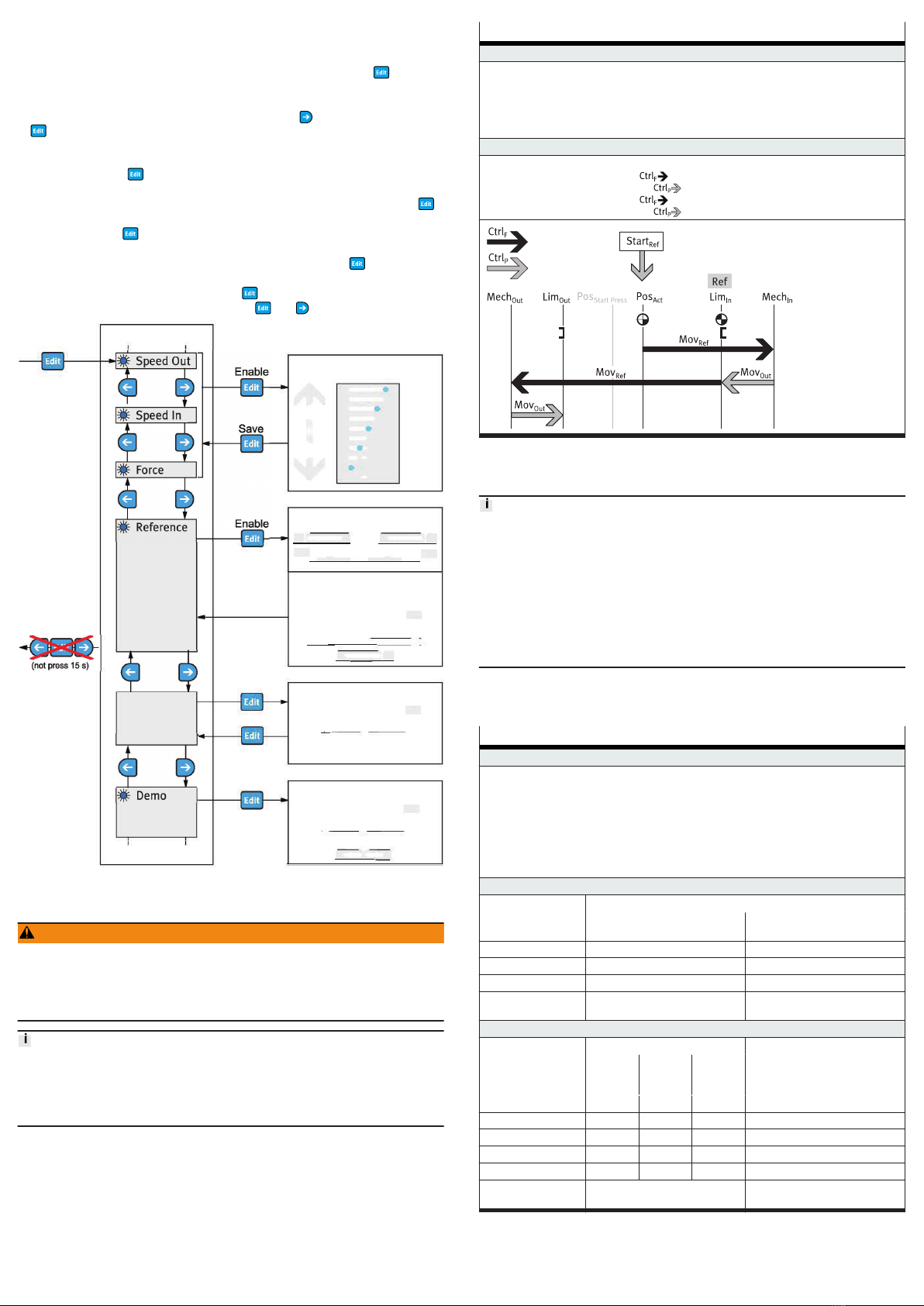
Fig. 8: HMI menu
9.5 Referencing with end position determination
WARNING
Risk of injury due to unexpected movement of components.
When starting the homing run, the drive is disconnected from the power supply
for a short time. This can cause unexpected movements of the connected
mechanics and crush parts of the body.
• Bring moving parts of the connected mechanical system into a safe position.
•Referencing with end position determination is only required again if the refer-
ence end position "Ref" or the useful range needs to be changed.
• During referencing with end position determination the intermediate position
PosImp and the start press position PosStart Press is set equal to the new end
position LimOut.
During referencing with end position determination the positions of the mechan-
ical stops MechIn/MechOut are recorded in order to calculate the end positions
LimIn ("Ref")/LimOut for the dimension reference system.
Before running referencing with end position determination to a new reference
end position "Ref", the drive is de-energized for a required re-initialisation. Then
the power is restored and the process is started.
Activate referencing with end position determination StartRef
Factory setting: motor-facing reference end position "Ref"
–HMI: activate "Reference" menu, parameterise reference end position "Ref" and initiate refer-
encing movement è 9.4 Display and operating components (HMI)
–IO-Link, process data: parameterise reference end position "Ref" 0x0103.0, false (factory setting)
or true and initiate referencing movement 0x0104.0 = true
–IO-Link, system parameter: 0x0002, value = 0xCE (Execute "Reference" Movement (False), factory
setting) or value = 0xCF (Execute "Reference" Movement (True))
Sequence
The diagram shows the referencing movements with end position determination
–MovRef: force-controlled movement against mechanical stop "MechIn"
–MovOut: position-controlled movement to the reference end position "Ref"
–MovRef: force-controlled movement against the mechanical stop "MechOut"
–MovOut: position-controlled movement to the end position LimOut
Tab. 5: Initialise referencing sequence with reference end position "Ref" and end
position determination
9.6 Point-to-point operating modes
Automatic saving of device data
If automatic storage is activated (0x0109.0 = true, default), parameter changes
in the device data (= data storage parameters è "Integrated drive EMCS"
instruction manual è www.festo.com/sp) are made automatically and perma-
nently saved in the flash memory. Exceeding the maximum permissible 100,000
write cycles results in irreparable damage to the flash memory and the device,
e.g. when using the device for positioning tasks via IO-Link.
If automatic saving is deactivated (0x0109.0 = false), parameter changes are
only temporarily stored in the RAM. The RAM permits an unlimited number of
parameter changes, e.g. for positioning tasks via IO-Link.
For single point-to-point operation the drive can be traversed to the target posi-
tions "end positions "LimIn/LimOut and intermediate positions PosImp" (IO-Link
only).
Point-to-point operation
Parameterise point-to-point operation
HMI:
–Speed Out, Speed In, Force and Start Press è 9.4 Display and operating components (HMI)
IO-Link (acyclic device data):
–Velocity Speed Out: 0x0101.0, Speed Out1)
–Velocity Speed In: 0x0100.0, Speed In1)
–Force/Torque: 0x0102.0, Force1)2)
–Start Press Position PosStart Press: 0x0105.0, Position Start Press [mm]2)3)4)
–End position LimOut: 0x0106.0, end position Out [mm]4)
–Intermediate position PosImp: 0x0108.0, Intermediate Position [mm]3)4)
Control point-to-point operation via digital inputs
Positioning task Control signals
MovIn
DI1 [Logic, Pin 5]
MovOut
DI2 [Logic, Pin 6]
StartIn/MovIn 1 0
StartOut/MovOut 0 1
Stop5) 0 0
Switch off output
stage6)
1 1
Control point-to-point operation via IO-Link
Positioning task Process parameters System parameters
Move "In" Move
"Out"
Move
"Inter-
mediate"
System commands
0x0029.1 0x0029.2 0x0029.5 0x0002
StartIn/MovIn true false false = 0xC8, Execute "MoveIn"
StartOut/MovOut false true false = = 0xC9, Execute "MoveOut"
StartImp/MovImp false false true = 0xD0, Execute "MoveIntermediate"
Stop5) false false false = 0xCA, stop motion
Switch off output
stage6)
³ 2 x true = 0xCB, disable power stage