Festo DHTG A Series Setup guide

Repair
instructions (en)
Rotary indexing table
DHTG-…-A
DHTG-…-A-P4/P4E4 / P4L12
7DHTGd_en

2 / 92 Festo 7DHTGd_en
Imprint
Version:
7DHTGd_en (04.2019)
Copyright:
©Festo AG & Co. KG
Postfach
73726 Esslingen
Germany
Editorial team:
Spare Part Documentation and
Support
Phone:
+49 / 711 / 347-0
Fax:
+49 / 711 / 347-2144
Email:
Internet:
http://www.festo.com
Reproduction, distribution or sale of
this document or communication of
its contents to others without express
authorisation is prohibited. Offenders
will be held liable for damages. All
rights reserved in the event that a
patent, utility model or design patent
is registered.
All product designations and brand
names used are the property of the
owners and not explicitly identied
as such.
All technical data are subject to
change according to technical
updates.

3 / 92Festo 7DHTGd_en
Foreword
These repair instructions are valid for the rotary indexing tables listed on the
title page to the exclusion of any liability claims.
Deviations compared to the descriptions in these repair instructions may arise
depending on the version and/or modication status of the rotary indexing
tables. The user must check this prior to carrying out the repair and take the
deviations into consideration if necessary.
These repair instructions have been prepared with care.
Festo AG & Co. KG does not, however, accept liability for any errors in these
repair instructions or their consequences. Likewise, no liability is accepted for
direct or consequential damage resulting from incorrect use of the products.
Further information is given in Chapter 8 on page 91.
The relevant regulations on occupational safety, safety engineering, and
interference suppression as well as the stipulations contained in these repair
instructions must be observed when working on the products.

4 / 92 Festo 7DHTGd_en
Table of Contents
1 Important information 6
1.1 About these repair instructions 6
1.2 Symbols used in these repair instructions 6
1.3 Text designations used in these repair instructions 7
1.4 General safety instructions 7
1.5 Technical requirements 8
1.6 Standards and test values 8
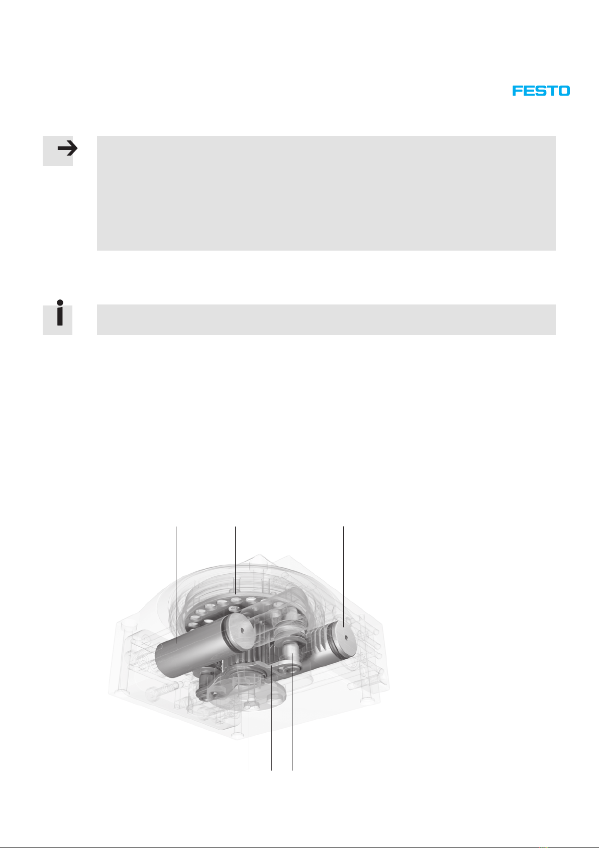
2 General product description 8
2.1 Functional description 8
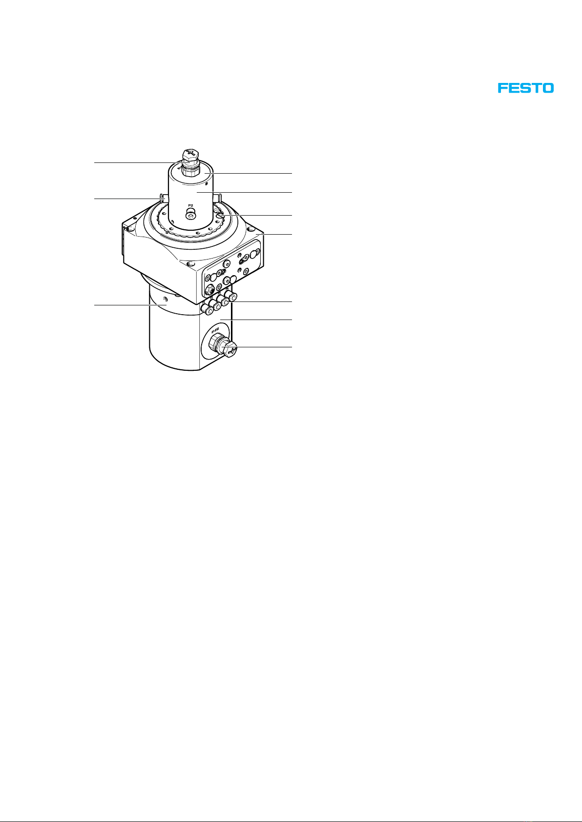
2.2 Energy throughfeed 9
2.2.1 DHTG-…-P4 9
2.2.2 DHTG-…-P4E4 9
2.2.3 DHTG-…-P4L12 10
2.3 Types and part or module numbers 11
2.3.1 Rotary indexing tables without energy throughfeed 11
2.3.2 Rotary index tables with energy throughfeed 11
2.4 Orientation designations 12
2.5 Type code 12
3 Component overviews and bill of materials 13
3.1 Components overview DHTG-65-…-A, series up to F7 (up to July 2015) 14
3.1.1 Bill of materials DHTG-65-…-A, Series up to F7 (up to July 2015) 15
3.2 Components overview DHTG-65-…-A, series from F8 (from August 2015) 16
3.2.1 Bill of materials DHTG-65-…-A, series from F8 (from August 2015) 17
3.3 Components overview DHTG-90-…-A, series up to F7 (up to July 2015) 18
3.3.1 Bill of materials DHTG-90-…-A, Series up to F7 (up to July 2015) 19
3.4 Components overview DHTG-90-…-A, series from F8 (from August 2015) 20
3.4.1 Bill of materials DHTG-90-…-A, series from F8 (from August 2015) 21
3.5 Components overview DHTG-140-…-A, series up to F7 (up to July 2015) 22
3.5.1 Bill of materials DHTG-140-…-A, Series up to F7 (up to July 2015) 23
3.6 Components overview DHTG-140-…-A, series from F8 (from August 2015) 24
3.6.1 Bill of materials DHTG-140-…-A, series from F8 (from August 2015) 25
3.7 Components overview DHTG-220-…-A, series up to F7 (up to July 2015) 26
3.7.1 Bill of materials DHTG-220-…-A, Series up to F7 (up to July 2015) 27
3.8 Components overview DHTG-220-…-A, series from F8 (from August 2015) 28
3.8.1 Bill of materials DHTG-220-…-A, series from F8 (from August 2015) 29
3.9 Components overview DHTG-65-…-A-P4 30
3.9.1 Bill of materials DHTG-65-…-A-P4 31
3.10 Components overview DHTG-65-…-A-P4E4 32
3.10.1 Bill of materials DHTG-65-…-A-P4E4 33
3.11 Components overview DHTG-65-…-A-P4L12 34
3.11.1 Bill of materials DHTG-65-…-A-P4L12 35
3.12 Components overview DHTG-90-…-A-P4 36
3.12.1 Bill of materials DHTG-90-…-A-P4 37
3.13 Components overview DHTG-90-…-A-P4E4 38
3.13.1 Bill of materials DHTG-90-…-A-P4E4 39
3.14 Components overview DHTG-90-…-A-P4L12 40
3.14.1 Bill of materials DHTG-90-…-A-P4L12 41

5 / 92Festo 7DHTGd_en
3.15 Components overview DHTG-140-…-A-P4 42
3.15.1 Bill of materials DHTG-140-…-A-P4 43
3.16 Components overview DHTG-140-…-A-P4E4 44
3.16.1 Bill of materials DHTG-140-…-A-P4E4 45
3.17 Components overview DHTG-140-…-A-P4L12 46
3.17.1 Bill of materials DHTG-140-…-A-P4L12 47
3.18 Components overview DHTG-220-…-A-P4 48
3.18.1 Bill of materials DHTG-220-…-A-P4 49
3.19 Components overview DHTG-220-…-A-P4E4 50
3.19.1 Bill of materials DHTG-220-…-A-P4E4 51
3.20 Components overview DHTG-220-…-A-P4L12 52
3.20.1 Bill of materials DHTG-220-…-A-P4L12 53
4 Repair steps 54
4.1 Preparatory steps 54
4.2 Visual inspection 54
4.3 Dismantling the energy throughfeed 55
4.3.1 Dismantling the rotary distributor, only DHTG-…-A-P4/ P4E4 / P4L12 55
4.3.2 Dismantling of the pneumatic and electrical module 57
4.4 Dismantling the rotary indexing table 58
4.4.1 Removing the plate 58
4.4.2 Dismantling the plate (DHTG-65 and DHTG-90) 59
4.4.3 Dismantling the plate (DHTG-140) 60
4.4.4 Dismantling the plate (DHTG-220) 62
4.4.5 Removing the gear racks 64
4.4.6 Removing the bolts 69
4.4.7 Dismantling the bolts 70
4.5 Mounting the rotary indexing table 71
4.5.1 Assembling the bolts 71
4.5.2 Installing the bolts 73
4.5.3 Installing the gear racks 74
4.5.4 Assembling the plate (DHTG-65 and DHTG-90) 80
4.5.5 Assembling the plate (DHTG-140) 81
4.5.6 Assembling the plate (DHTG-220) 82
4.5.7 Installing the plate 84
4.6 Mounting the energy throughfeed 86
4.6.1 Mounting of the pneumatic and electrical module 86
4.6.2 Mounting the rotary distributor, only DHTG-…-A-P4/ P4E4 / P4L12 86
5 Cleaning 90
6 Maintenance 90
6.1 Cleaning and lubricating the rotary indexing table 90
6.2 Inspection interval for the shock absorber 90
7 Tools 91
8 Liability 91

6 / 92 Festo 7DHTGd_en
1 Important information
1.1 About these repair instructions
This document contains important information about proper repair of the rotary indexing table type DHTG-…-A and
DHTG-…-A-P4 / -P4E4 / -P4L12.
However, the costs of carrying out a repair must be considered in the case of larger defects.
Before carrying out a repair, the relevant chapter in these instructions must be read in full and followed consistently.
For reasons of clarity, these repair instructions do not contain all detailed information. The following documents should
therefore also be available when repairing the rotary indexing table:
– Operating instructions: Rotary indexing table DHTG and energy throughfeed DHTG-…-P4/-P4E4 / -P4L12
Contain information on the peripherals of the respective product as well as about the function, structure, ap-
plication, installation, commissioning, maintenance and care, etc. They are available on the Festo website
(www.festo.com/sp).
– Assembly instructions: Energy throughfeed DHTG-P4 and rotary throughfeed DHAS-SCR12-H6
Contain information on the assembly / dismantling of the respective product, they are available on the Festo website
(www.festo.com/sp).
– Spare parts documentation
Contains an overview of the spare and wearing parts as well as information on their installation. This can be found in
the online spare parts catalogue on the Festo website (www.festo.com/spareparts).
– “Tools and repair accessories” information brochure
Contains an overview of available assembly aids (e.g. lubricants, locking agent), special tools, schematic diagrams,
xtures, measuring devices, etc. The information can be found in the online spare parts catalogue on the Festo
website (Tools and repair accessories.pdf).
1.2 Symbols used in these repair instructions
Danger categories
The following symbols identify text passages which draw attention to specic hazards.
Warning
Caution
Marking special information
The following symbols identify text passages which contain special information.
Note
Information
Environment

7 / 92Festo 7DHTGd_en
1.3 Text designations used in these repair instructions
• Activities that can be carried out in any order.
.1 Activities which should be carried out in the specied order.
– General list
Result of an activity /references to further information
Underlined, blue text indicates a cross-reference or hyperlink that you can click on in the PDF.
1.4 General safety instructions
Warning
The rotary indexing table must only be repaired by authorised and trained persons in accordance with the specica-
tions in the technical documentation and using genuine spare parts.
Installation and repair by unauthorised and untrained persons, repairs using non-original spare parts or without the
technical documentation required for installation and/or repair are dangerous and therefore not permitted.
Repairs must only be carried out in conjunction with these repair instructions and the respective device-specic oper-
ating instructions.
Caution
Unintended switching on can trigger unexpected movements and cause bruises.
• Ensure that the unit is protected against restarting before any modication or maintenance work or inspections
are carried out. Loosened parts can make unexpected movements or fall off.
• Secure parts against accidental movements or move them into a safe end position.
Caution
Lifting large loads can lead to permanent injury.
• Depending on their size and weight, the products must be lifted by several persons or using suitable lifting gear.
Note
Carrying out repair work without the respective necessary technical documentation is dangerous, and therefore not
permissible. Repairs must only be carried out in conjunction with these repair instructions and the respective operat-
ing instructions for the device, as well as the documents listed in Chapter 1.1 on page 6.
In the event of damage caused by unauthorised manipulation, improper use or use of non-original spare parts, all
warranty and liability claims against the manufacturer expire.
Instead of carrying out the repair yourself, your local Festo sales ofce offers the option of having the repair carried
out by Festo.
Note
• Observe the given tightening torques. If no special information is given the tightening torques given in the relevant
standard apply to the screws, bolts and nuts used.
• Note the strength class of the screws, bolts and nuts!
Components and equipment replaced during repair must be disposed of in accordance with the relevant local environ-
mental protection regulations.

8 / 92 Festo 7DHTGd_en
1.5 Technical requirements
Note
The following instructions for safe and proper use must be observed:
– Observe the connection and ambient conditions specied in the technical data of the products and all the connect-
ed components. The product can only be operated in compliance with the relevant safety guidelines if you comply
with the limit values and load limits (see enclosed documentation).
– The rotary indexing table must be in perfect technical condition.
– The rotary indexing table may only be operated in its original condition and without unauthorised modications.
– The rotary indexing table is designed for industrial use.
1.6 Standards and test values
Standards and test values which products comply with and full can be found in the “Technical data” sections of the
enclosed documentation.
2 General product description
2.1 Functional description
The DHTG-…-A is a rotary indexing table based on the rack and pinion principle for power transmission and forced lock-
ing. The linear motion of two pneumatically actuated rack pistons is converted into swivel motion by a pinion. A second
pair of pistons controls meshing of the pinion in the table gearing and locking of the holding position.
The DHTG rotary indexing table's intended use is to turn the mass of the workpiece through a dened rotation angle into
a holding position.
As an additional function, an energy throughfeed can be selected in the versions P4 (purely pneumatic) and P4E4, P4L12
(pneumatic / electrical).
3
2
1
45
11Gear rack
2Index plate
3Pinion
4Metal sheet
5Bolt for locking the index plate

9 / 92Festo 7DHTGd_en
2.2 Energy throughfeed
Electrical signals or compressed air can be transferred through the hollow shaft using the energy throughfeed.
2.2.1 DHTG-…-P4
Energy throughfeed: pneumatic, 4 channels
4
2
3
1
7
6
5
1End cap
2Flat head screw
3Rotary indexing table (DHTG)
4 Push-in tting, input
5Energy throughfeed, pneumatic
module
6Rotary distributor
7 Push-in tting, output
2.2.2 DHTG-…-P4E4
Energy throughfeed: pneumatic, 4 channels and electrical, 4 signals
4
2
5
3
1
aJ
9
8
6
7
1End cap assembly
2Rotary distributor
3Flat head screw
4Rotary indexing table (DHTG)
5 Push-in tting, input
6Energy throughfeed, electrical
module
7Flanged plug, input
8Energy throughfeed, pneumatic
module
9 Push-in tting, output
aJ Flanged plug, output

10 / 92 Festo 7DHTGd_en
2.2.3 DHTG-…-P4L12
Energy throughfeed: pneumatic, 4 channels and electrical, 12 cables
4
2
5
3
1
aJ
8
9
6
7
1End cap assembly
2Rotary distributor
3Flat head screw
4Rotary indexing table (DHTG)
5 Push-in tting, input
6Energy throughfeed, electrical
module
7Flanged plug, input
8Energy throughfeed, pneumatic
module
9 Push-in tting, output
aJ Flanged plug, output

11 / 92Festo 7DHTGd_en
2.3 Types and part or module numbers
The complete overview of features, accessories, type codes, technical data and dimensions of the rotary indexing tables
can be found in the product catalogue and on the Festo website (www.Festo.com).
2.3.1 Rotary indexing tables without energy throughfeed
Type Part number
DHTG-65-2-A 548076
DHTG-65-3-A 555448
DHTG-65-4-A 548077
DHTG-65-6-A 548078
DHTG-65-8-A 548079
DHTG-65-12-A 548080
DHTG-65-24-A 548081
DHTG-90-2-A 548082
DHTG-90-3-A 555449
DHTG-90-4-A 548083
DHTG-90-6-A 548084
DHTG-90-8-A 548085
DHTG-90-12-A 548086
DHTG-90-24-A 548087
DHTG-140-3-A 555450
DHTG-140-4-A 548088
DHTG-140-6-A 548089
DHTG-140-8-A 548090
DHTG-140-12-A 548091
DHTG-140-24-A 548092
DHTG-220-3-A 555451
DHTG-220-4-A 548093
DHTG-220-6-A 548094
DHTG-220-8-A 548095
DHTG-220-12-A 548096
DHTG-220-24-A 548097
2.3.2 Rotary index tables with energy throughfeed
Type Module number
DHTG-65-…-A-P4 / P4E4 / P4L12 575738
DHTG-90-…-A-P4 / P4E4 / P4L12 575739
DHTG-140-…-A-P4 / P4E4 / P4L12 575740
DHTG-220-…-A-P4 / P4E4 / P4L12 575741

12 / 92 Festo 7DHTGd_en
2.4 Orientation designations
These illustrations give an overview of the direction designations of the rotary indexing tables.
Orientation:
O = top
U = bottom
R = right
L = left
V = front
H = rear
2.5 Type code
The precise features of a rotary indexing table can be determined with the help of the two sets of product labelling on the
rotary indexing table. The order code describes the features of the rotary indexing table, separated by a dash “-”.
Rotary indexing table product labelling:
Example:
DHTG-220-4-A
548093 H7
p max: 8bar
1
32
1Order code
2Serial number
3Part number
The order code on the product labelling provides the following information:
DHTG Rotary indexing table
220 Size
4Pitch
AFor proximity sensor
Additional product labelling only with energy throughfeed:
Example:
Complete Unit:
DHTG-220
575741 H802
1
32
1Designation
2Serial number
3Part number

13 / 92Festo 7DHTGd_en
3 Component overviews and bill of materials
The data sheet contains a list and description of all possible equipment features of the product (www.festo.com).
The component overviews with corresponding bills of materials for the following rotary indexing tables are listed on the
following pages:
Rotary indexing tables without energy throughfeed
Size Part number Components list Bill of materials
DHTG-65-…-A 548076 Series up to F7 (up to July 2015)
Chapter 3.1 on page 14
Series from F8 (from August 2015)
Chapter 3.2 on page 16
Series up to F7 (up to July 2015)
Chapter 3.1.1 on page 15
Series from F8 (from August 2015)
Chapter 3.2.1 on page 17
555448
548077
548078
548079
548080
548081
DHTG-90-…-A 548082 Series up to F7 (up to July 2015)
Chapter 3.3 on page 18
Series from F8 (from August 2015)
Chapter 3.4 on page 20
Series up to F7 (up to July 2015)
Chapter 3.3.1 on page 19
Series from F8 (from August 2015)
Chapter 3.4.1 on page 21
555449
548083
548084
548085
548086
548087
DHTG-140-…-A 555450 Series up to F7 (up to July 2015)
Chapter 3.5 on page 22
Series from F8 (from August 2015)
Chapter 3.6 on page 24
Series up to F7 (up to July 2015)
Chapter 3.5.1 on page 23
Series from F8 (from August 2015)
Chapter 3.6.1 on page 25
548088
548089
548090
548091
548092
DHTG-220-…-A 555451 Series up to F7 (up to July 2015)
Chapter 3.7 on page 26
Series from F8 (from August 2015)
Chapter 3.8 on page 28
Series up to F7 (up to July 2015)
Chapter 3.7.1 on page 27
Series from F8 (from August 2015)
Chapter 3.8.1 on page 29
548093
548094
548095
548096
548097
Rotary index tables with energy throughfeed
Size Module number Components list Bill of materials
DHTG-65-…-A-P4 575738 Chapter 3.9 on page 30 Chapter 3.9.1 on page 31
DHTG-65-…-A-P4E4 Chapter 3.10 on page 32 Chapter 3.10.1 on page 33
DHTG-65-…-A-P4L12 Chapter 3.11 on page 34 Chapter 3.11.1 on page 35
DHTG-90-…-A-P4 575739 Chapter 3.12 on page 36 Chapter 3.12.1 on page 37
DHTG-90-…-A-P4E4 Chapter 3.13 on page 38 Chapter 3.13.1 on page 39
DHTG-90-…-A-P4L12 Chapter 3.14 on page 40 Chapter 3.14.1 on page 41
DHTG-140-…-A-P4 575740 Chapter 3.15 on page 42 Chapter 3.15.1 on page 43
DHTG-140-…-A-P4E4 Chapter 3.16 on page 44 Chapter 3.16.1 on page 45
DHTG-140-…-A-P4L12 Chapter 3.17 on page 46 Chapter 3.17.1 on page 47
DHTG-220-…-A-P4 575741 Chapter 3.18 on page 48 Chapter 3.18.1 on page 49
DHTG-220-…-A-P4E4 Chapter 3.19 on page 50 Chapter 3.19.1 on page 51
DHTG-220-…-A-P4L12 Chapter 3.20 on page 52 Chapter 3.20.1 on page 53
The following diagrams are intended only to provide an overview of the individual components. To order spare and
wearing parts, please use the online spare parts catalogue on the Festo website (www.festo.com/spareparts).

14 / 92 Festo 7DHTGd_en
3.1 Components overview DHTG-65-…-A, series up to F7 (up to July 2015)

15 / 92Festo 7DHTGd_en
3.1.1 Bill of materials DHTG-65-…-A, Series up to F7 (up to July 2015)
No. Designation, type
1 Flat head screw, DIN 921-M3×6-5.8
2 Clamping ring
3 Plate seal
4 Rail
5 Rail
6 Ball bearing
7 Bearing module
8 O-ring, 14×2
9 Plate
10 Index plate
11 Cylindrical dowel pin, DIN 6325-6M6×10
12 Countersunk screw, DIN 7991-M4×8-8.8
13 Retaining ring, DIN 472-18×1
14 End cap
15 O-ring, 11.5×1.5
16 Wiper seal
17 O-ring, 2.2×1
18 Stop pin
19 Compression spring, D-001
20 Lock bolt
21 Bolt
22 Piston seal
23 Housing
24 Pinion
25 Metal sheet
26 Cover
27 Retaining ring, DIN 471-18×1.2
28 Flange
29 Cylindrical dowel pin, DIN 6325-4M6×12
30 Socket head screw, DIN 7984-M4×8-8.8
31 Countersunk screw, DIN 7991-M5×16-8.8
32 Plate module
33 Sealing ring, OK-M3
34 Plug screw, B-M3-S9
35 Blanking plug, B-M3-S9
36 Piston seal
37 Gear rack
No. Designation, type
38 O-ring, 24.8×1.5
39 O-ring, 3×1.5
40 Shock absorber, YSRD- 8- 8-C
41 Retaining ring, DIN 472-12×1
42 O-ring, 8×1.6
43 Buffer, SLT-6
44 Compression spring, D-055
45 Plate module
46 Socket head screw, DIN 912-M4×16-8.8
47 Stop screw, M8×1×12
48 Clamping component, DGSL-10
49 Sealing ring, OK-M5
50 Plug screw, B-M5-B
51 Blanking plug, B-M5-B
52 Stop screw, M8×1×…
53 Hollow bolt module, GRLA-M5-B
54 Pinion module
55 Lubricating grease LUB-E1, silicone-free

16 / 92 Festo 7DHTGd_en
3.2 Components overview DHTG-65-…-A, series from F8 (from August 2015)

17 / 92Festo 7DHTGd_en
3.2.1 Bill of materials DHTG-65-…-A, series from F8 (from August 2015)
No. Designation, type
1 Flat head screw, DIN 921-M3×6-5.8
2 Clamping ring
3 Plate seal
4 Rail
5 Rail
6 Ball bearing
7 Bearing module
8 O-ring, 14×2
9 Plate
10 Index plate
11 Spring pin, 3×12
12 Cylindrical dowel pin, DIN 6325-6M6×10
13 Countersunk screw, DIN 7991-M4×8-8.8
14 Retaining ring, DIN 472-18×1
15 End cap
16 O-ring, 11.5×1.5
17 Wiper seal
18 O-ring, 2.2×1
19 Stop pin
20 Compression spring, D-001
21 Lock bolt
22 Bolt
23 Piston seal
24 Housing
25 Pinion
26 Metal sheet
27 Cover
28 Retaining ring, DIN 471-18×1.2
29 Flange
30 Cylindrical dowel pin, DIN 6325-4M6×12
31 Socket head screw, DIN 7984-M4×8-8.8
32 Countersunk screw, DIN 7991-M5×16-8.8
33 Plate module
34 Sealing ring, OK-M3
35 Plug screw, B-M3-S9
36 Blanking plug, B-M3-S9
37 Piston seal
No. Designation, type
38 Gear rack
39 O-ring, 24.8×1.5
40 O-ring, 3×1.5
41 Shock absorber, YSRD- 8- 8-C
42 Retaining ring, DIN 472-12×1
43 O-ring, 8×1.6
44 Buffer, SLT-6
45 Compression spring, D-055
46 Plate module
47 Socket head screw, DIN 912-M4×16-8.8
48 Stop screw, M8×1×12
49 Clamping component, DGSL-10
50 Sealing ring, OK-M5
51 Plug screw, B-M5 B
52 Blanking plug, B-M5-B
53 Stop screw, M8×1×…
54 Hollow bolt module, GRLA-M5-B
55 Pinion module
56 Lubricating grease LUB-E1, silicone-free
The new F8 series (from August 2015)
differs from the previous series only due to
an additional heavy-duty spring pin in the
plate (www.festo.com/spareparts).

18 / 92 Festo 7DHTGd_en
3.3 Components overview DHTG-90-…-A, series up to F7 (up to July 2015)

19 / 92Festo 7DHTGd_en
3.3.1 Bill of materials DHTG-90-…-A, Series up to F7 (up to July 2015)
No. Designation, type
1 Flat head screw, DIN 921-M3×6-5.8
2 Clamping ring
3 Plate seal
4 Rail
5 Rail
6 Ball bearing
7 Bearing module
8 O-ring, 20×2
9 Plate
10 Index plate
11 Countersunk screw, DIN 7991-M5×12-8.8
12 Cylindrical dowel pin, DIN 6325-8M6×16
13 Retaining ring, DIN 472-25×1.2
14 End cap
15 O-ring, 20×1.5
16 Wiper seal
17 O-ring, 2.2×1
18 Stop pin
19 Compression spring, D-001
20 Lock bolt
21 Bolt
22 Piston seal
23 Housing
24 Pinion
25 Metal sheet
26 Cover
27 Retaining ring, DIN 471-24×1.2
28 Flange
29 Cylindrical dowel pin, DIN 6325-4M6×12
30 Socket head screw, DIN 912-M4×8-8.8
31 Countersunk screw, DIN 7991-M5×16-8.8
32 Plate module
33 Sealing ring, OK-M3
34 Plug screw, B-M3-S9
35 Blanking plug, B-M3-S9-OK
36 Piston seal
37 Gear rack
No. Designation, type
38 O-ring, 28×1.5
39 O-ring, 5×1.5
40 O-ring, 3×1.5
41 Shock absorber, YSRD- 8- 8-C
42 Retaining ring, DIN 472-12×1
43 O-ring, 8×1.6
44 O-ring, 12×2
45 Compression spring, D-055
46 Plate module
47 Socket head screw, DIN 912-M4×16-8.8
48 Stop screw, M8×1×12
49 Clamping component, DGSL-10
50 Sealing ring, OK-M5
51 Plug screw, B-M5 B
52 Blanking plug, B-M5-B-OK
53 Stop screw, M8×1×…
54 Hollow bolt module, GRLA-M5-B
55 Pinion module
56 Lubricating grease LUB-E1, silicone-free

20 / 92 Festo 7DHTGd_en
3.4 Components overview DHTG-90-…-A, series from F8 (from August 2015)
This manual suits for next models
71
Table of contents
Other Festo Power Tools manuals

Festo
Festo MAS Series User manual

Festo
Festo DNCE-...-LAS-...-C Series User manual

Festo
Festo YJKP Assembly instructions

Festo
Festo DNCKE Series User manual

Festo
Festo DNCKE Series User manual

Festo
Festo CLR Series User manual

Festo
Festo SLE Series User manual

Festo
Festo DHDS User manual

Festo
Festo BV-50- 40 User manual

Festo
Festo DRQD-8 Product guide