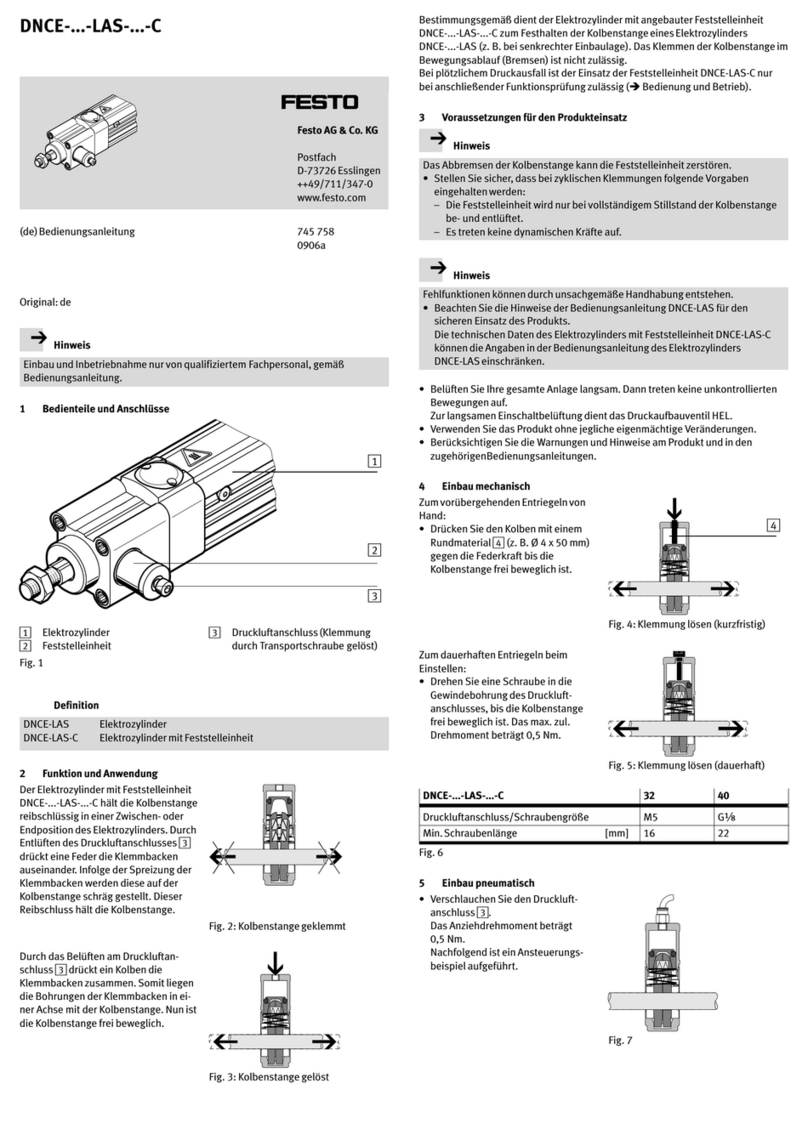
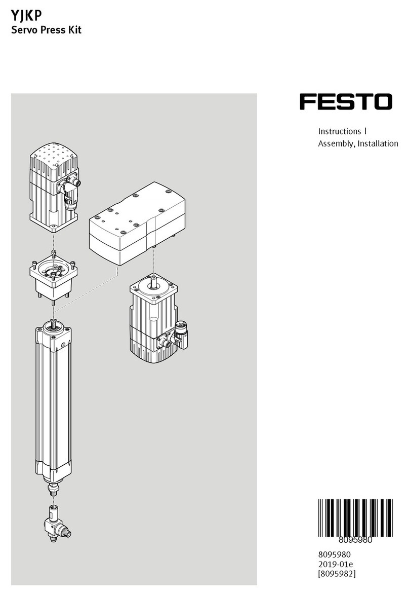
Festo YJKP Assembly instructions

Translation of the original instructions
CANopen®, EtherNet/IP®, MODBUS®, PI PROFIBUS PROFINET® are registered
trademarks of the respective trademark owners in certain countries.
1 About this document
1.1 Further applicable documents
All available documents for the product èwww.festo.com/pk.
User documentation
Name, type Link, contents
Sensor SKDA-...-AB (operating instructions) èwww.festo.com/sp
Electric drive ESBF-BS (operating instructions) èwww.festo.com/sp
Axial kit EAMM-A (assembly instructions) èwww.festo.com/sp
Parallel kit EAMM-U (assembly instructions) èwww.festo.com/sp
Servo motor EMMS-AS-55 (operating instruc-
tions)
èwww.festo.com/sp
Servo motor EMMS-AS-70 (operating instruc-
tions)
èwww.festo.com/sp
Servo motor EMMS-AS-100 (operating instruc-
tions)
èwww.festo.com/sp
Servo motor EMMS-AS-140 (operating instruc-
tions)
èwww.festo.com/sp
Motor controller CMMP-AS-...-M0 (user docu-
mentation)
èwww.festo.com/sp
Controller CECC-X-M1 (user documentation) èwww.festo.com/sp
Encoder cable NEBM-M (assembly instructions) èwww.festo.com/sp
Encoder cable NEBM-T1G8 (assembly instruc-
tions)
èwww.festo.com/sp
Motor cable NEBM-M23G8 (assembly instruc-
tions)
èwww.festo.com/sp
Motor cable NEBM-T1G8 (assembly instructions) èwww.festo.com/sp
Connecting cable NEBU-M12G5-E-...-LE3
(assembly instructions)
èwww.festo.com/sp
Connecting cable NEBC-S1WA9-P-1.5-N-BB-L2G4
(assembly instructions)
èwww.festo.com/sp
Connecting cable NEBC-S1G25-P-1.5-N-LE6
(assembly instructions)
èwww.festo.com/sp
Tab. 1 Further applicable documents on the Servo Press Kit
Additional media
Name, type Table of contents
Web Help YJKP Operation of the software for servo press kit YJKP
Application note Application examples for connection and com-
missioning
èwww.festo.com/sp
Tab. 2 Additional media on the Servo Press Kit
The range of application and certifications of the individual components of the kit
are described in separate documents èwww.festo.com/sp.
2 Safety
2.1 Intended use
This product is a module for execution of joining tasks with monitoring of the join-
ing process. The module can be used within machines or automated systems with
a higher-order controller.
Use the product only as follows:
– in perfect technical condition
– in its original condition, without unauthorised modifications
– Within the limits of the product defined by the technical data
– in an industrial environment
– permanently mounted
2.2 Foreseeable misuse
Never use the product as follows:
– with unauthorised modifications or alterations to the product
– with load limits exceeded
– in an invalid mounting position
2.3 Qualification of specialized personnel
Only qualified personnel may perform installation, commissioning, maintenance
and disassembly of the product.
The qualified personnel must be familiar with installation of mechatronic systems.
3 Additional information
– Accessories èwww.festo.com/catalogue.
– Spare parts èwww.festo.com/spareparts.
4 Service
Contact your regional Festo contact person if you have technical questions
èwww.festo.com.
5 Product overview
1Servo motor EMMS-AS
2Axial/parallel kit EAMM-A/U
3Electric drive ESBF-BS
4Sensor SKDA-...-AB
5Connecting cable
NEBU-M12G5-E-...-LE3
6Encoder cable NEBM
7Motor cable NEBM
8LAN cable (not included in the
delivery)
9Connecting cable
NEBC-S1WA9-P-1.5-N-BB-L2G4
10 Controller CECC-X-M1-YS
11 Memory card
12 Motor controller CMMP-AS
13 Connecting cable
NEBC-S1G25-P-1.5-N-LE6
14 Higher-order controller (not
included in the delivery)
15 Laptop (not included in the deliv-
ery)
Fig. 1
6 Transport
6.1 Sequence of transport and unpackaging
NOTICE!
Damage to the product due to incorrect transport.
• Observe the transport labelling and information on the packaging.
1. Transport the product to the installation/storage location in its packaging and
set it down on a firm and flat base.
2. When storing: Pay attention to the storage conditions è 14 Technical data.
8076678
Servo Press Kit
YJKP
8076678
2017-12d
[8076680]
Instructions| Assembly, Installation
Festo AG & Co. KG
73734 Esslingen
Ruiter Straße 82
Germany
+49 711 347-0
www.festo.com

NOTICE!
Damage to the product due to incorrect unpacking.
• Observe the labelling and information on unpacking shown on the packaging.
• Unpack the product with at least 2 persons present.
• Use appropriate tools.
• Parts of the packaging are large and heavy:
– Do not let any parts fall onto the product.
– Use suitable aids to raise and lower the product (e.g. crane).
3. Remove the packaging in accordance with the printed sequence.
6.2 Restraints in the packaging
Transport restraints prevent uncontrolled movement of the product in the pack-
aging during transport and installation. The product is provided with the following
designated transport restraints:
Fig. 2
Fig. 3
7 Mounting
7.1 Preparation
7.1.1 Fitting space
The fitting space required for the product depends on the selected size of the
Servo Press Kit and the following factors:
– Stroke of the electric cylinder èwww.festo.com/catalogue
– Attachment position and type of motor
Unintentional lowering of the piston rod is possible at any time. The axis cannot
be pushed back manually. If necessary, the electric cylinder may need to be dis-
mantled.
7.1.2 Mounting surface
The mounting surface must exhibit the following characteristics:
– torsionally rigid
– free of stress
– sufficient strength to absorb the maximum forces
– sufficient evenness
7.2 Assembly
WARNING!
Risk of injury due to lowering piston rod.
• Before working on the product: Secure the piston rod to prevent it from
lowering.
CAUTION!
Risk of injury due to falling product.
• Make sure the mounting surface is sufficiently strong to absorb the maximum
forces.
• Only use the supplied mounting components.
• Secure the screw connections.
In the Servo Press Kit, the electric drive, axial or parallel kit and servo motor can
be pre-assembled. With individual components, the following assembly steps are
required.
7.2.1 Assemble the motor mounting kit
Depending on the configuration, an axial or parallel kit can be assembled.
Assemble the axial kit EAMM-A
Fig. 4
èPay attention to the accompanying documentation: Axial kit EAMM-A
(assembly instructions)
èwww.festo.com/sp
• Assemble the axial kit EAMM-A
Assemble the parallel kit EAMM-U
Fig. 5
èPay attention to the accompanying documentation for EAMM-U.
èwww.festo.com/sp
• Assemble the parallel kit EAMM-U.
7.2.2 Mount the drive unit on the frame
èPay attention to the accompanying documentation for ESBF.
èwww.festo.com/sp
• Mount the complete unit consisting of axis, axial/parallel kit and motor on the
customer-provided frame so that it is tension-free.
7.2.3 Assemble the sensor SKDA
Fig. 6
èPay attention to the accompanying documentation for SKDA.
èwww.festo.com/sp
1. Do not screw the lock nut up to the stop on the ESBF-BS.
2. Screw the sensor on the ESBF-BS.
3. Apply the lock nut to secure the sensor.
7.2.4 Additional steps
1. Insert the memory card (microSD card) into the CECC-X-M1-YS.
2. Assemble the CECC-X-M1-YS.
èPay attention to the accompanying documentation for the CECC-X-M1-YS.
èwww.festo.com/sp
3. Assemble the CMMP-AS.
èAccompanying documentation for the CMMP-AS.
èwww.festo.com/sp
Up-to-date information on the accessories èwww.festo.com/catalogue.
8 Installation
8.1 Safety
WARNING!
Risk of injury due to lowering piston rod.
• Before working on the product: Secure the piston rod to prevent it from
lowering.
WARNING!
Risk of injury due to unexpected movement of the product.
Electrical energy can cause unexpected movement of the product.
• Before working on the product: Switch off the power supply, ensure that it is
off and secure it against being switched on again.

NOTICE!
Material damage as a result of using the wrong connections.
In accordance with intended use, all unnamed connections must not be used.
Details on handling the individual components of the kit are described in separate
documents èwww.festo.com/sp.
8.2 Electrical installation - cables
8.2.1 Connecting cable NEBU-M12G5-E-...-LE3
The connecting cable connects the sensor on the electric drive with the analogue
input [X19] on the controller.
The accompanying connector must be assembled on the open cable ends.
Sensor SKDA Controller
CECC-X-M1-YS
Connection Pin Wire colour1) Usage Pin Connection
[X19]
1 BN 24VDC
Power supply for
sensor
X19.0.1
2 – –
3 BU Input 4…20mA
Evaluation of the
sensor signal
through servo
press software
X19.0.2
4 BK Not used
5 – –
1) colour code in accordance with IEC 60575:1983-01
Tab. 3 Sensor connecting cable - analogue inputs [X19]
1. Connect connecting cable to the sensor.
2. Place the open cable ends in the connector provided in accordance with the
table.
3. Insert the plug into the controller connection [X19.0].
8.2.2 Connecting cable NEBC-S1WA9-P-1.5-N-BB-L2G4
The connecting cable connects the CANopen interface [X4] of the motor controller
with the CANopen interface [X18] of the controller.
The cable is readily assembled.
1. Insert the plug into the connection [X4] of the motor controller.
2. Insert the plug into the connection [X18] of the controller.
8.2.3 Connecting cable NEBC-S1G25-P-1.5-N-LE6
The connecting cable is used to provide power to the digital controller interface
[X1] of the motor controller.
The wiring should be carried out in accordance with the following table.
Motor controller
CMMP-AS-...-M0
Provided by the cus-
tomer
Connection
[X1]
Pin Wire colour1) Usage Type
YJKP
Connection
0.8/ 1.5/ 4 GND7 BN Fieldbus: Offset
node number
bit 17/ 12/ 17 +24VDC
8 YE Fieldbus: Offset
node number
bit 3
all GND
9 GY Controller
enable
all +24VDC
0.8/ 1.5/
7/ 12
GND19 WH Fieldbus: Offset
node number
bit 04/ 17 +24VDC
20 GN Fieldbus: Offset
node number
bit 2
all GND
21 PK Output stage
enable
all +24VDC
1) colour code in accordance with IEC 60575:1983-01
Tab. 4 Connecting cable wiring, digital control interface [X1]
1. Insert plug into the connection [X1] of the motor controller.
2. Place the open cable ends in accordance with the table.
If a customer-specific connecting cable is used, the following PIN must also be
laid:
Motor controller
CMMP-AS-...-M0
Provided by the
customer
Connection [X1] Pin Wire colour1) Usage Connection
3, 11 - - GND
16, 23 - - +24VDC
1) colour code in accordance with IEC 60575:1983-01
Tab. 5 Connecting cable wiring, digital control interface [X1] - customer-specific
1. Insert plug into the connection [X1] of the motor controller.
2. Place the additional open cable ends in accordance with the table also.
8.2.4 Motor cable NEBM-M23G8-E-...-Q9N-LEB; NEBM-T1G8-E-...-Q7N-LEB
The motor cable connects the connection [X6] on the servo motor with the connec-
tion [X6] on the motor controller. The wiring should be carried out in accordance
with the following table.
The wiring should be carried out in accordance with the following table.
Servo motor EMMS-AS Motor controller
CMMP-AS
Connection
[X6]
Pin Wire colour1) Usage Pin Connection
[X6]
2 Motor power
supply
8 V
3 Motor power
supply
7 W
1 Motor power
supply
9 U
GN/YE Motor power
supply
6 PE
WH Temperature
sensor
5 +MTdig
BN Temperature
sensor
4 -MTdig
GN Brake (optional) 2 BR+
YE Brake (optional) 1 BR-
1) colour code in accordance with IEC 60575:1983-01
Tab. 6 Motor cable
1. Insert the plug into the connection [X6] of the servo motor.
2. Place the open cable ends in accordance with the table in the connection [X6]
of the motor controller.
8.2.5 Encoder cable NEBM-M12W8-E-...-N-S1G15;
NEBM-T1G8-E-...-N-G1G15
The encoder cable connects the connection [X2] on the servo motor with the con-
nection [X2B] on the motor controller.
The cable is readily assembled.
NOTICE!
Restart single-turn encoder.
Loss of the reference position.
• Homing is required at the restart of the encoder.
1. Insert the plug into the connection [X2] of the servo motor.
2. Insert the plug into the connection [X2B] of the motor controller.
8.3 Electrical installation CECC-X-M1-YS
8.3.1 Overview of interfaces
1Ethernet interface [X8]
2USB interface [X9]
3Functional earth connection
4I/O interfaces [X2, X3, X4]
5Power supply [X1]
Fig. 7
1Status LEDs
2Memory card
3Power supply [X5] for digital out-
puts
4CANopen interface [X18]
5Digital outputs [X20]
6Digital inputs [X17]
7Analogue inputs [X19]
Fig. 8
NOTICE!
Material damage as a result of using the wrong connections.
In accordance with intended use, all unnamed connections must not be used.

The status LEDs show the operating status of the controller.
Status LED Meaning
Run Application status
Error Errors
Net Device detected
Mod reserved
Tab. 7 Status LEDs
8.3.2 Overview of connection and plug/cable: CECC-X-M1-YS
Connection Plug/cable Purpose
[X1] NECC-L2G4-C11) Power supply for device
[X5] NECC-L2G2-C11) Power supply for digital outputs
[X2] NECC-L2G8-C11)
[X3] NECC-L2G6-C11)
[X4] NECC-L2G4-C11)
I/O interface
[X8] Standard LAN patch cable2) Ethernet interface
[X9] USB interface
[X17] 2x NECC-L2G6-C11) Digital inputs
[X18] NECC-L2G4-C1 CANopen interface
[X20] NECC-L2G2-C11) Digital outputs
1) Plug for customer-provided cable
2) not included in the scope of delivery of the kit
Tab. 8 Connection and plug
8.3.3 Power supply [X1]
WARNING!
Risk of injury due to electric shock.
• For the electric power supply, use only PELV circuits that ensure a reliable
electric disconnection from the mains network.
• Observe IEC60204-1/EN60204-1.
– Power supply for device, digital and analogue inputs
–Resultant current for all supplied ports: £750mA
–Of which intrinsic current consumption: £200mA
– Use an external overload protection for the power supply of the device.
Terminal Connection Usage
X1.1 24 24V DC
X1.2 0 0V DC
X1.3 Functional earth
X1.4 Unused –
Tab. 9 Power supply connection for device, digital and analogue inputs
1. Supply the device with power.
2. Place the open cable ends in the connector provided in accordance with the
table.
3. Insert the plug into the connection [X1] of the controller.
8.3.4 Power supply [X5]
– Power supply for digital outputs.
–Resultant current for all supplied ports: £5A
Terminal Connection Usage
X5.1 24 24VDC
X5.2 0 0VDC
Tab. 10 Connection, power supply for digital outputs
1. Supply the device with power.
2. Place the open cable ends in the connector provided in accordance with the
table.
3. Insert the plug into the connection [X5] of the controller.
8.3.5 I/O interface [X2, X3, X4]
Terminal Connection Usage
X2.0…X2.7 8 digital inputs Configurable as step enabling
condition in the sequencer of
the press process: DI1…DI81)
X3.0 Start press process1)
Manual operating mode: Plot
the reference curve
Automatic operating mode:
Start the press process
X3.1 “Manual” operating mode1)
X3.2 "Automatic B" operating
mode1)
X3.3 Referenzfahrt starten1)
X3.4
6 digital inputs
Acknowledge error1)
Terminal Connection Usage
X3.5 6 digital inputs Terminate press process 1)2)
X4.0…X4.3 4 digital outputs Configurable as output signals
in the sequencer of the press
process: DO1 …DO41)
24VDC output set by the soft-
ware as soon as certain event
occurs (position reached, force
reached).
X4.4…X4.7 Unused –
1) For details, see online help
2) Process termination if input = FALSE.
Tab. 11 I/O interface connection
8.3.6 Ethernet interface [X8]
The Ethernet interface is designed as an RJ45 socket and supports gigabit LAN.
The following protocols are supported:
– EtherNet/IP (server)
– ModbusTCP (Server)
– Ethernet TCP/IP
– PROFINET IO
The interface [X10] of the controller is not supported. The controller cannot be
used as a switch.
The Ethernet interface is used to configure and parameterise the system through
a PC/tablet connected to the network. After the mechanical and electrical installa-
tion, the servo press kit can be commissioned with a web browser. Control and
process data can be exchanged with a higher-order controller through this inter-
face during the run-time of the system.
A requirement for this is integration of the CECC-X-M1-YS in the local network.
Minimum requirements for a PC/tablet
– Web browser with Java Script and support of HTML5 Canvas, e.g. Firefox,
Chrome, Internet Explorer ³ Version9
– Screen resolution 1024 x 768 pixels
Access is through entry in the address line:
http://<<IP address>>:8080/servo_press_kit.htm
Example: http://192.168.4.2:8080/servo_press_kit.htm
NOTICE!
Unauthorised access to the device can cause damage or malfunctions.
When connecting the device to a network, protect the network from unauthorised
access.
Measures to protect the network include:
• Firewall
• Intrusion prevention system (IPS)
• Network segmentation
• Virtual LAN (VLAN)
• Virtual private network (VPN)
• Security at physical access level (port security)
Further informationèDirectives and standards for security in information tech-
nology, e.g.IEC62443, ISO/IEC27001.
8.3.7 USB interface [X9]
The controller offers the option of connecting the USB memory stick up to 32GB to
the USB interface [X9] and saving the press results.
The USB interface is compatible with the USB 3.0 and USB 2.0 standards. It is
suitable for USB plug type A.
8.3.8 Digital inputs [X17]
The digital inputs, configured in 3-wire connection technology, are not galvanic-
ally separated. The ground potential for all inputs relates to GND of the power
supply [X1].
For connecting additional sensors (e.g. external cylinder limit switches, workpiece
inspection) with 3-wire connection technology: Use 3 adjacent terminals each.
NOTICE!
Material damage or loss of function due to incorrect I/O circuitry.
• All digital inputs/outputs are designed as PNP. Use only corresponding cir-
cuitry.
Terminal Connection Usage
X17.0.1 24VDC Power supply 24VDC for pro-
gram selection bit 01)
X17.0.2 Input DI9 Program selection bit 0
X17.0.3 GND logic Power supply GND sensor for
program selection bit 0
X17.1.1 24VDC Power supply 24VDC sensor
for program selection bit 1
X17.1.2 Input DI10 Program selection bit 1
X17.1.3 GND logic Power supply GND sensor for
program selection bit 1
X17.2.1 24VDC Power supply 24VDC sensor
for program selection bit 2
Terminal Connection Usage
X17.2.2 Input DI11 Program selection bit 2
X17.2.3 GND logic Power supply GND sensor for
program selection bit 2
X17.3.1 24VDC Power supply 24VDC sensor
for program selection bit 3
X17.3.2 Input DI12 Program selection bit 3
X17.3.3 GND logic Power supply GND sensor for
program selection bit 3
X17.4.1 24VDC Power supply 24VDC2)
X17.4.2 Servo press activation Release of motor controller out-
put stage via controller
CECC-X-M1-YS
X17.4.3 GND logic Power supply GND2)
X17.5.1 24VDC Power supply24VDC2)
X17.5.2 Activation of step operation Press process in step operation
X17.5.3 GND logic Power supply GND2)
X17.6.1…X17.6.3 Unused –
X17.7.1…X17.7.3 Unused –
1) optional
2) reserve
Tab. 12 Connection of digital inputs
8.3.9 Digital outputs [X20]
The digital outputs, configured in 2-wire connection technology, are galvanically
separated. The current load for each output is 0.5A.
The ground potential for all outputs relates to GND of the power supply [X5]. All
outputs are protected against short circuit and thermal overload.
NOTICE!
Material damage or loss of function due to incorrect I/O circuitry.
• All digital inputs/outputs are designed as PNP. Use only corresponding cir-
cuitry.
Fig. 9
Use 2 adjacent terminals when connecting a consumer.
Terminal Connection Assignment Comments
X20.0.1 Signal P Errors 0.5 A per channel, SSR
1)2)
X20.0.2 Unused – –
X20.1.1 Signal P Servo press ready for
operation
0.5 A per channel, SSR
1)2)
X20.1.2 Unused – –
X20.2.1 Signal P Homing requirement 0.5 A per channel, SSR
1)2)
X20.2.2 Unused – –
X20.3.1 Signal P Press result OK 0.5 A per channel, SSR
1)2)
X20.3.2 Unused – –
X20.4.1 Signal P Press result not OK 0.5 A per channel, SSR
1)2)
X.20.4.2 Unused – –
X20.5.1 Signal P Servo press activated –
X20.5.2 Unused – –
X20.6.1 Signal P Program step com-
pleted
–
X20.6.2 Unused – –
X20.7.1…X20.7.2 Unused – –
1) SSR: Solid State Relay
2) For details, see online help
Tab. 13 Terminal allocation of digital outputs
8.3.10 Card slot for memory card
• Plug the memory card laterally into the device so the system can run.
ÄConfigurations, programs and results of press processes can be stored.
8.4 Electrical installation CMMP-AS
8.4.1 Overview of interfaces
1Activation of firmware download
2Activation of CANopen terminat-
ing resistor
3CANopen interface [X4]
4Ethernet interface [X18]
57-segments display
6Reset button
7Status LEDs
8Digital I/O interface for control of
the STO function [X40]
Fig. 10
1Digital control interface [X1]
2Power supply [X9]
3PE connection
Fig. 11
1Motor connection [X6]
2Encoder connection [X2B]
Fig. 12

NOTICE!
Material damage as a result of using the wrong connections.
In accordance with intended use, all unnamed connections must not be used.
The status LEDs show the operating status of the motor controller.
Status LED Meaning
Ready/Error Status
Enable release
CAN CAN bus status display
Tab. 14 Status LEDs
8.4.2 Overview of connection and plug/cable: CMMP-AS
Connection Plug/cable Purpose
[X1] Connecting cable
NEBC-S1G25-P-1.5-N-LE6
Digital control interface for cus-
tomer connection
[X2B] Encoder cable Connection for servo motor
encoder connection
[X4] Connecting cable
NEBC-S1WA9-P-1.5-N-BB-L2G4
Connection for controller
CECC-X-M1-YS
[X6] Motor cable Connection for servo motor con-
nection
[X9] Plug1) Power supply
[X18] Standard LAN patch cable2) Ethernet interface
[X40] Plug connector1) Interface for STO function
1) Plug for customer-provided cable
2) not included in the scope of delivery of the kit
Tab. 15 Connection and plug
8.4.3 Basic setting of DIP switch
The two DIP switches on the motor controller CMMP-AS must be set to a defined
basic setting in this application.
1. Set switch [S2] to the position 0.
2. Set switch [S3] t the position 0.
8.4.4 Power supply [X9]
• Connect the power supply in accordance with the table
è 1.1 Further applicable documents.
Force range Power supply
Up to 4kN 100…230V AC (1 phase)
Ab 7kN 230…480VAC (3 phases)
Tab. 16 Power supply
8.4.5 Ethernet interface [X18]
The Ethernet interface is used to for the connection with the higher-order control-
ler.
8.5 I/O interface for STO [X40]
The STO function is described in the additional documents
è 1.1 Further applicable documents.
Motor controller Design on the device Counterplug
CMMP-AS PHOENIX MINICOMBICON MC
1.5/8-GF-3.81 BK
PHOENIX MINICOMBICON MC
1.5/8-STF-3.81 BK
Tab. 17 Plug design [X40]
[X40] Pin Designation Value Specification
1 STO-A 0V / +24VDC Control input A for
the function STO
2 0V-A 0V Reference potential
for STO-A
3 STO-B 0V / +24VDC Control input B for
the function STO
4 0V-B 0V Reference potential
for STO-B
5 C1 – Acknowledgment
contact for the STO
status on an extern-
al controller
6 C2 – Acknowledgment
contact for the STO
status on an extern-
al controller
7 24V +24VDC Output for auxiliary
power supply
(24VDC logic sup-
ply of the motor
controller brought
out)
8 0V 0V Reference potential
for auxiliary power
supply
Tab. 18 Assignment [X40]: I/O interface for STO
8.5.1 Circuitry with use of the STO safety function [X40]
• To work safely with the STO safety function (safe torque off), please observe
the additional information in the further applicable documents
è 1.1 Further applicable documents.
9 Commissioning
WARNING!
Risk of injury due to unexpected movement of the product.
Electrical energy can cause unexpected movement of the product.
• Before working on the product: Switch off the power supply, ensure that it is
off and secure it against being switched on again.
The first steps for commissioning the servo press kit are made with the help of the
Festo Field Device Tool (FFT èwww.festo.com/sp).
Requirements
– PC with FFT as well as control and motor controller are connected over the
same network.
– Participants (control, motor controller) are connected directly over a switch.
Port Manual TCP/UDP
161 PROFINET (use of SNMP)
80, 8080 HTTP. Access to the servo press
software
TCP
20, 21 FTP TCP
1024 - 65535 FTP logging
Depending on the FTP server
configuration, ports in this area
have to be released.
TCP
4444 Control of servo press via
TCP/IP
TCP
502 Modbus® TCP
44818 EtherNet/IP TCP
2222 EthernetIP UDP
10002 Festo Field Device Tool UDP/TCP
Tab. 19 Ports for servo press controller
Preparation with the FFT
1. Preparation with the FFT: Set network parameters of the controller
CECC-X-M1-YS.
2. Set network parameters of the motor controller CMMP-AS.
3. Optional: Update firmware and software.
– Firmware update for controller CECC-X-M1-YS
– Firmware update for motor controller CMMP-AS
– Software update for servo press software on the controller CECC-X-M1-YS
Examples with explanations in the application notes from Festo
èwww.festo.com/sp.
NOTICE!
Increased wear in case of operation with too little stroke.
• Observe the minimum stroke.
• If undercut: minimum stroke of 12.5mm must be traversed 10 times in every
100 movement cycles.
10 Maintenance
10.1 Safety
WARNING!
Risk of injury due to lowering piston rod.
• Before working on the product: Secure the piston rod to prevent it from
lowering.
WARNING!
Risk of injury due to unexpected movement of the product.
Electrical energy can cause unexpected movement of the product.
• Before working on the product: Switch off the power supply, ensure that it is
off and secure it against being switched on again.
10.2 Maintenance work
The maintenance work required for the individual components of the kit is
described in the further applicable documents
è 1.1 Further applicable documents.
Interval Maintenance work
Check the mounting of the force sensor.
Check the toothed belt for wear and pretension.
If the toothed belt breaks, the axis can fall down
in an uncontrolled manner.
at least once a year - depending on the number
of movements and load
Check the mounting of the coupling on a regular
basis.
Tab. 20

10.3 Cleaning
NOTICE!
Material damage due to incorrect cleaning.
• Do not clean the guide elements.
• Clean product only with non-abrasive cleaning agents and a soft cloth.
The procedure for cleaning the individual components of the kit is described in
the further applicable documents è 1.1 Further applicable documents.
11 Repair
Repair is described in separate documents èwww.festo.com/sp.
For additional support for repairs: Consult your regional Festo contact.
12 Dismounting
WARNING!
Risk of injury due to unexpected movement of the product.
Electrical energy can cause unexpected movement of the product.
• Before working on the product: Switch off the power supply, ensure that it is
off and secure it against being switched on again.
WARNING!
Risk of injury due to unexpected movement of the product when lifting it.
• Secure movable components with transport locks to prevent unexpected
movement.
• Use all of the transport lugs.
• Observe the position of the centre of gravity.
Details on handling the individual components of the kit are described in separate
documents èwww.festo.com/sp.
13 Disposal
ENVIRONMENT!
Send the packaging and product for environmentally sound recycling in accord-
ance with the current regulations èwww.festo.com/sp.
14 Technical data
14.1 General features
Servo press Kit YJKP 0.8 1.5 4 7 12 17
Max. pressing force [kN] 0.8 1.5 4 7 12 17
Max. payload [kg] 19.5 19.5 48 48 95 95
PLC interface Ethernet
Duty cycle [%] 100 1)
Mounting position Optional
Control CECC-X-M1-YS
Motor controller
CMMP-AS-...-M0
C2-3A C5-3A C5-11A-P3 C10-1-
1A-P3
Servo motor EMMS-AS-...-HS 55-M 70-S 100-S 100-M 140-L
Electric cylinder
Electric drive ESBF-BS-...-5P 32-...2) 40-...2) 50-...2) 63-...2) 80-...2) 100-...
2)
Spindle pitch [mm] 5
Repetition accuracy [mm] ± 0.01 ± 0.015 ± 0.01
Feed speed [mm/s] £250 £160
Acceleration 3) [m/s2] 2
Deceleration 4) [m/s2] 2
Quick-stop deceleration [m/s2] 5
Motor attachment position Axial, parallel
Vibration and shock resist-
ance 5)
SG2 / SG2
Force sensor
Force sensor SKDA-...-AB 0.8 1.5 4 7 12 17
Max. overload [kN] ± 1.5 ± 3.75 ± 11.25 ± 15 ± 30 ± 37.5
Scanning frequency [Hz] 1000
Accuracy of measurement [%FS] £± 0.25
Vibration and shock resist-
ance5)
SG3 / SG2
1) The system can permanently press with nominal force against a component/load (with v less than 50
mm/s).
2) Working stroke [mm]: 100, 200, 300, 400
3) Acceleration for positioning procedures
4) Deceleration when force is reached
5) in accordance with IEC 60068-2-6/EN 60068-2-6
Tab. 21 Technical data YJKP
14.2 Technical data of the main components
Controller
CECC-X-M1-YS
Operating voltage [X1, X5] [VDC] 19.2…30
Operating voltage [X21] [VDC] 19.2…50
Nominal current consump-
tion at 24VDC
[mA] 200
Reverse polarity protection No
Fan noise LpAeq (1m dis-
tance)
[dB(A)] 35.7
Memory card
Supported type microSD
Capacity [GByte] 32
File system FAT32
Analogue input [X19]
Input signal [mA] 0…20
Resolution 14 bits
Hardware
Processor (CPU) Dual core, 2 x 866 MHz
Total main memory [MByte] 512
Tab. 22 Technical data
Motor controller
CMMP-AS
C2-3A-
M0
C5-3A-
M0
C5-11A-
P3-M0
C10-11A-
P3-M0
Nominal voltage [VDC] 24 ± 20 %
Nominal voltage 1) [A] 0.55 0.65 1
Max. current for holding
brake
[A] 1 2
Type of mounting Screwed onto sub-base
Display 7-segments display
Protocol ModbusTCP, EtherNet/IP, TCP/IP, PROFINET
Dimensions (HxWxD) 2) [mm] 202x66x207 227x66x207 252x79x247
Mounting plate dimensions [mm] 248x61 297x75
1) Plus current consumption from an existing holding brake and I/Os
2) Without plug, shield screw and screw heads
Tab. 23 Technical data
14.3 Product weight
Servo press Kit YJKP 0.8 1.5 4 7 12 17
CECC-X-M1-YS [kg] 0.41
CMMP-AS-...-M0 [kg] 2.1 2.2 3.5
Servo motor
Servo motor EMMS-AS-...-HS 55-M 70-S 100-S 100-M 140-L
Basic weight [kg] 1.6 2.1 4.8 6.9 16.2 16.2
Additional weight of brake [kg] 0.1 0.2 0.5 0.6 0.8 0.8
Electric cylinder
Electric drive ESBF-BS-...-5P 32-a 40-a 50-a 63-a 80-a 100-a
Basic weight with 0mm
stroke
[kg] 0.781 1.237 1.982 3.163 7.393 7.393
Additional weight per
100mm stroke
[kg] 0.33 0.47 0.65 0.87 1.55 1.55
Force sensor
Force sensor SKDA-..-AB 0.8 1.5 4 7 12 17
Basic weight [kg] 0.2 0.2 0.3 0.3 0.7 0.7
Connecting kit
Parallel kit [kg] 1.05 2.45 4.99 4.95 11.9 11.8
Axial kit [kg] 0.26 0.41 1.14 1.17 2.92 3.46
Tab. 24 Technical data, product weight
14.4 Operating and storage conditions
Feature
Storage temperature [°C] –10…+60
Storage location Dry, solid and flat base (in original packaging)
Max. storage time 48 months
Ambient temperature [°C] 0…+40
Air humidity [%] 0…90 (non-condensing)
Corrosion resistance class
CRC
01)

Feature
Permissible setup altitude above sea level
At nominal power [m] 1000
With performance reduction
2)
[m] 1000…2000
1) No corrosion stress. Applies to small, optically irrelevant standard parts such as threaded pins, circlips and
clamping sleeves which are usually only available on the market in a phosphated or burnished version
(and possibly oiled) as well as to ball bearings (for components < CRC 3) and plain bearings.
2) Above 1000 m above sea level, performance reduction of 1 % per 100 m
Tab. 25 Technical data, operating and storage conditions
14.5 Severity level (SL) for vibration and shock
Vibration load
Frequency range [Hz] Acceleration [m/s2] Deflection [mm]
Severity
level 1
Severity
level 2
Severity
level 1
Severity
level 2
Severity
level 1
Severity
level 2
2…8 2…8 – – ± 3.5 ± 3.5
8…27 8…27 10 10 – –
27…58 27…60 – – ± 0.15 ± 0.35
58…160 60…160 20 50 – –
160…200 160…200 10 10 – –
Tab. 26 Vibration load
Shock load
Acceleration [m/s2] Duration [ms] Shocks per direction
Severity
level 1
Severity
level 2
Severity
level 1
Severity
level 2
Severity
level 1
Severity
level 2
± 150 ± 300 11 11 5 5
Tab. 27 Shock load
Continuous shock load
Acceleration [m/s2] Duration [ms] Shocks per direction
± 150 6 1000
Tab. 28 Continuous shock load
Other manuals for YJKP
2
Other Festo Power Tools manuals

Festo
Festo DRQD-8 Product guide

Festo
Festo DNCKE Series User manual

Festo
Festo DNCKE Series User manual

Festo
Festo CLR Series User manual

Festo
Festo DHTG A Series Setup guide

Festo
Festo MAS Series User manual

Festo
Festo DMSP Series User manual

Festo
Festo YJKP Series Assembly instructions

Festo
Festo BV-50- 40 User manual

Festo
Festo SLE Series User manual
Popular Power Tools manuals by other brands

Hitachi
Hitachi NV 90HMC Technical data and service manual

Orgapack
Orgapack OR-T 300 Short instruction: Operating and maintenance

Grizzly
Grizzly T23094 owner's manual

Dremel
Dremel 8200 Original instructions

Jet
Jet JTM-949EVS/230 Operating instructions and parts manual

HOLZMANN MASCHINEN
HOLZMANN MASCHINEN SB 4132SM user manual