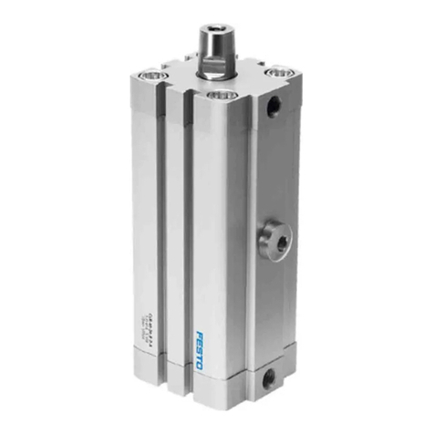
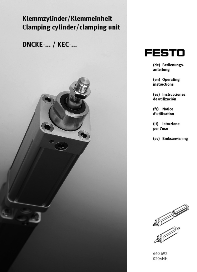
Festo DNCKE Series User manual

8098628
DNCKE-...-S / KEC-...-S
Cylinder with clamping unit/Clamping unit
8098628
2018-12d
[8098630]
Instructions | Operat-
ing

Translation of the original instructions
2 Festo — DNCKE-...-S / KEC-...-S — 2018-12d

3Festo — DNCKE-...-S / KEC-...-S — 2018-12d
1 Design.......................................................................................................................... 4
2 Safety........................................................................................................................... 5
2.1 Intended use................................................................................................................ 5
2.2 Foreseeable misuse...................................................................................................... 6
2.3 Specified standards...................................................................................................... 6
2.4 General safety instructions........................................................................................... 6
2.5 Mounting and connecting............................................................................................. 6
2.6 Training of qualified personnel..................................................................................... 6
3 Function........................................................................................................................7
4 Transport..................................................................................................................... 7
5 Installation.................................................................................................................. 7
5.1 Mechanical installation................................................................................................. 7
5.1.1 Mounting the clamping unit....................................................................................8
5.1.2 Mounting attachments............................................................................................9
5.1.3 Mounting accessories.............................................................................................10
5.2 Pneumatic installation.................................................................................................. 10
5.2.1 Requirements......................................................................................................... 10
5.2.2 Functional tests...................................................................................................... 11
5.2.3 Creating a tubing connection to the clamping unit..................................................12
6 Commissioning............................................................................................................ 13
6.1 Dismantling the round material (only required for KEC).................................................13
6.2 Adjustment of the clamping unit................................................................................... 15
6.3 Test run......................................................................................................................... 17
6.4 Checking clamping force/overtravel............................................................................. 18
7 Operation and use....................................................................................................... 23
7.1 Regular adjustment of the clamping unit...................................................................... 24
8 Maintenance and care................................................................................................. 24
9 Disassembly and repair............................................................................................... 24
10 Disposal........................................................................................................................25
11 Accessories.................................................................................................................. 25
12 Fault clearance............................................................................................................ 25
13 Technical data............................................................................................................. 26
14 Characteristic curves................................................................................................... 28
Table of contents
1 Design
NOTICE!
Documentation on the product
All available documents for the product èwww.festo.com/pk
1Supply port for cylinder next to the adjusting
screws for the pneumatic cushioning (only
for DNCKE)
2Supply port for releasing the clamp
3Locking screw with internal hexagon socket
(for adjusting sleeve)
4Piston rod (DNCKE only)
5Adjusting sleeve with spanner flat
6Hollow bolts with thread for mounting
7Hole with filter element for exhausting the
clamping chamber
8Slots for proximity sensors (DNCKE only)
9Round material for transportation lock (KEC
only)
Fig. 1
Design
Festo — DNCKE-...-S / KEC-...-S — 2018-12d4

Definition
In these operating instructions, the designation “clamping unit” is used for:
• The individual product KEC
• The design type DNCKE integrated in the cylinder
In these operating instructions, the designation “round material” is used for:
• The transportation lock for KEC
• The piston rod for DNCKE
1DNCKE-...-S 2KEC-...-S
Fig. 2
2 Safety
2.1 Intended use
The clamping unit KEC is intended to serve both as an individual product and integrated into a cylinder
DNC (for cylinder with clamping unit DNCKE) for the following usage:
– As a safety device for holding and clamping round material.
– As a well-tried component for braking a linear movement (stopping a movement) for processing or
handling procedures in a normal industry environment without substances and ambient condi-
tions that influence the function or materials used.
The product has been checked by the Institute for Occupational Safety and Health and is documented
by a DGUV test certificate.
If used as a braking device, e.g. for interrupting potentially dangerous movements in a danger zone, a
regular check of the overtravel as a factor of the travel speed and the frequency of the braking proced-
ures (increased wear) as well as of the ambient operating conditions (min./max. temperature) is
necessary.
Safety
5Festo — DNCKE-...-S / KEC-...-S — 2018-12d

2.2 Foreseeable misuse
The clamping unit is not suitable for positioning tasks or for transmitting torques and lateral forces. A
self-aligning rod coupler (è 11 Accessories) can prevent the transmission of lateral forces and bend-
ing moments.
2.3 Specified standards
Version
DINENISO12100:2011-03
DINENISO4414:2011-04
DINENISO13849-1:2008-12
Tab. 1 Standards specified in the document
2.4 General safety instructions
– Observe legal regulations applicable to the destination.
– Only use the product if it is in its original condition and in perfect working order.
– Use the product only within the defined values (è 13 Technical data).
– Observe product labelling.
– Observe further applicable documents.
– Take into consideration the ambient conditions at the location of use.
– Protect the product during storage and operation from the following:
– Wetness or moisture
– Corrosive coolant or other materials (e.g. ozone)
– UV radiation
– Oils, greases and grease-solvent vapours
– Grinding dust
– Glowing chips or sparks
The operating modes must guarantee that the residual risk is smaller/equal to the accepted risk
(èDINENISO12100). The measures for risk reduction are to be taken in accordance with
DINENISO4414, DINENISO12100 and DINENISO13849-1.
Monitor/check the function of the entire system during use in accordance with the measures defined
in the validation report (èDINENISO13849-2).
2.5 Mounting and connecting
•Observe tightening torques. Unless otherwise specified, the tolerance is ±20%.
2.6 Training of qualified personnel
Only qualified personnel may install, commission, service or disassemble the clamping unit. The
skilled personnel must be familiar with the installation of electrical and pneumatic control systems.
Safety
6 Festo — DNCKE-...-S / KEC-...-S — 2018-12d

3 Function
Pressurising with compressed air on the supply port 2 (è Fig.1) opens the internal clamping com-
ponent through a pneumatically driven release mechanism. The round material can then move freely.
Fig. 3
If the supply port is exhausted, a spring-loaded mechanism generates the clamping force of the clamp-
ing component. The round material is then clamped.
Fig. 4
4 Transport
• Take product weight into account (è 13 Technical data).
5 Installation
5.1 Mechanical installation
Requirements
NOTICE!
Lateral loads and bending moments exerted on the round material damage its function and destroy
the internal clamping component.
• Make sure that the loads are only exerted on the round material in the direction of movement. The
use of a self-aligning rod coupler (è 11 Accessories) prevents lateral forces.
NOTICE!
Movement of the round material against the clamping forces leads to heavy wear on the internal
clamping component and the round material.
• Make sure that the holding force is never exceeded. Otherwise, unexpected movement may occur.
– Make sure that the clamping unit is installed as follows:
– Operating elements always accessible
– Product secured free from distortion and deflection
– Direct reaction forces via the mounting components as compressive force. Observe the braking
direction r (è Tab. 2 ).
Function
7Festo — DNCKE-...-S / KEC-...-S — 2018-12d

– Check whether safety measures (e.g. toothed latches or moving bolts) are also required externally
(èDINENISO12100 and DINENISO13849-1).
– Select the installation type for the desired application. Refer to the Festo catalogue for more
mounting alternatives (è Tab. 2 ) and required accessories.
5.1.1 Mounting the clamping unit
Interfaces for mounting components on the cover
e.g. with foot mounting HNC1)
(only permitted for use as a holding device)
e.g. with flange mounting FNC1)
(permitted for use as a holding and braking
device – observe braking direction r)
1) è www.festo.com/catalogue
Tab. 2
Installation
8 Festo — DNCKE-...-S / KEC-...-S — 2018-12d

Dimensions (see catalogue information)1)
Clamping unit KEC Clamping unit (with cylinder) DNCKE
1) è www.festo.com/catalogue
1) èwww.festo.com/catalogue
Tab. 3
DNCKE 40 63 100Size
KEC 16 20 25
L11) [mm] 178 208.5 287
ZJ+ (plus stroke length) [mm] 277 315 408
TG [mm] 38 56.5 89
E [mm] 54 80 126
Screw-in depth [mm] 9.5 ... 15 12.5 ... 14 14 ... 17
Screw M6 (4x) M8 (4x) M10 (4x)
Tightening torque [Nm] 5 13 30
1) Dimension varies depending on setting of the adjusting screw.
Tab. 4
1. Place the clamping unit in the intended position.
2. Tighten screws evenly (tightening torques è Tab. 4).
5.1.2 Mounting attachments
Mounting on the DNCKE
• Mount the attachment component on the piston rod. The spanner flat aJ on the piston rod serves
as a counter holder for the lock nut. If necessary, secure the lock nut with a screw locking agent.
Fig. 5
Installation
9Festo — DNCKE-...-S / KEC-...-S — 2018-12d

5.1.3 Mounting accessories
If proximity sensors are used in the cylinder with clamping unit DNCKE:
– Use Festo accessory proximity sensors (èwww.festo.com/catalogue).
– Place the proximity sensors in the grooves 8 of the cylinder.
– Fasten the proximity sensors in the desired switching positions.
8Slot
Fig. 6
5.2 Pneumatic installation
5.2.1 Requirements
• Check if the following accessories are required:
Designation Type Function
Slow pressure reduction with loss of compressed
air
Check valve HGL
Redundancy with “stop function”
Compensation reservoir VZS Reduction of pressure fluctuations in the follow-
ing compressed air line
Tab. 5
• Use a one-way flow control valve type (e.g. GRLZ or GRLA) directly in the relevant supply port.
For activating the cylinder with clamping unit:
– Select a suitable activation type for the specific application.
Installation
10 Festo — DNCKE-...-S / KEC-...-S — 2018-12d

Example for clamping unit activation
2 functions are possible:
– Protection against unexpected start-up of the piston rod (holding function)
– Stopping a dangerous movement of the piston rod (emergency brake function)
Before the clamping unit is released, measures must be taken to prevent the piston rod from advan-
cing suddenly.
Fig. 7
5.2.2 Functional tests
Functional test when used as a holding device (clamping function)
The frequency (test interval) of a static functional test is to be determined based on the applica-
tion/risk assessment and the category selected in accordance with DINENISO13849. In addition, the
static functional test, if not required by C-type standards or other regulations, must be performed at
least once per month and every 100,000 switching cycles.
Functional test when used as an emergency braking device (emergency brake/emergency stop func-
tion)
In principle, a static functional test and a dynamic braking test are required after every emergency
brake (emergency stop).
The frequency (test interval) of a dynamic braking test is to be determined based on the applica-
tion/risk assessment and the category selected in accordance with DINENISO13849. In addition, the
dynamic braking test, if not required by C-type standards or other regulations, must be performed at
least once per year. After the dynamic braking test, a static functional test must be performed.
Information on conducting the static functional test and the dynamic braking test
(è 6.4 Checking clamping force/overtravel).
Installation
11Festo — DNCKE-...-S / KEC-...-S — 2018-12d

5.2.3 Creating a tubing connection to the clamping unit
When operated in normal ambient air (without particles):
– Remove covers (if present) from the supply ports.
– Remove dirt particles and foreign matter from the ports and tubing lines.
– Use the shortest suitable tubing lines. This will reduce switching times.
– Connect the tubing to the supply ports of the clamping unit 2 and to the supply ports of the cylin-
der 1 in accordance with DINENISO4414.
2Supply port for clamping unit 1Supply port for cylinder
Fig. 8
DNCKE 40 60 100Size
KEC 16 20 25
Supply port for clamp-
ing unit
2G 1/8 G 1/4 G 3/8
Supply port for cylinder
(DNCKE only)
1G 1/4 G 3/8 G 1/2
Tab. 6
Installation
12 Festo — DNCKE-...-S / KEC-...-S — 2018-12d

When operated in ambient air containing fine dust and mist to prevent dirt particles from entering the
pneumatic system:
1. Use a barbed fitting (e.g. QS-CM-M5) instead of the filter nipple in the exhaust channel 7 of the
spring interior.
2. Route the hose in an area with clean ambient air.
Fig. 9
6 Commissioning
WARNING!
Unexpected movement of components. Injury due to impacts or crushing.
• Protect positioning range from access (e.g. using protective guards).
• Make sure that no foreign objects are present in the positioning range.
NOTICE!
• Ensure that:
– Adjustment is only performed by qualified personnel.
– The holding force corresponds to the specified values
(è 6.4 Checking clamping force/overtravel).
– The critical limit values are not exceeded (è 13 Technical data).
NOTICE!
Clamping without round material will destroy the internal clamping component
• Make sure that the clamping unit KEC is always pressurised when the round material is not inser-
ted.
If the clamping unit KEC is exhausted when the round material is not inserted, the high spring
force will deform the internal clamping component until it cannot function.
6.1 Dismantling the round material (only required for KEC)
1. Pressurise the supply port 2 with at least 3.8bar.
Commissioning
13Festo — DNCKE-...-S / KEC-...-S — 2018-12d

2Supply port 3Locking screw
Fig. 10
2. Loosen the locking screw 3 using an Allen key.
DNCKE 40 63 100Size
KEC 16 20 25
Spanner size for intern-
al hexagon socket 3 ß
[mm] 6 8
Tab. 7
5Adjusting sleeve 9Round material
Fig. 11
3. Unscrew the adjusting sleeve 5 half a turn in an anticlockwise direction.
4. Pull supplied round material 9 out completely.
NOTICE!
If the round material is inserted at an angle, the scraper and seals might be damaged.
• A 15° chamfer at least 3mm wide at the end of the round material ensures it can be slid on
easily (workpiece quality è 13 Technical data).
Commissioning
14 Festo — DNCKE-...-S / KEC-...-S — 2018-12d

Fig. 12
5. Slide the clamping unit onto the rod of the attachment product carefully.
6. Adjust the KEC to the new round material (è 6.2 Adjustment of the clamping unit).
6.2 Adjustment of the clamping unit
Adjustment is not required for initial start-up of DNCKE.
1. Exhaust the cylinder in a stable position (e.g. if installed vertically, at the lowest point).
2Supply port 3Locking screw
Fig. 13
2. Pressurise the supply port 2 with at least 3.8bar.
3. Loosen the locking screw 3 using an Allen key.
DNCKE 40 63 100Size
KEC 16 20 25
Spanner size for intern-
al hexagon socket 1 ß
[mm] 6 8
Tab. 8
Commissioning
15Festo — DNCKE-...-S / KEC-...-S — 2018-12d

5Adjusting sleeve
Fig. 14
4. Unscrew the adjusting sleeve 5 half a turn in an anticlockwise direction.
5Adjusting sleeve
Fig. 15
5. Turn the adjusting sleeve 5 clockwise until the round material can no longer move.
6. Turn the adjusting sleeve 5 anticlockwise until the round material is just free to move (approx.
10–30°).
3Locking screw
Fig. 16
7. Re tighten the locking screw 3. The tightening torque is 7Nm.
8. Exhaust the clamping unit. The round material is then clamped.
Commissioning
16 Festo — DNCKE-...-S / KEC-...-S — 2018-12d

6.3 Test run
• Comply with critical limits for all loads.
For setting the speed and pneumatic cushioning:
11 One-way flow control valve
12 Pneumatic cushioning
Fig. 17
1. First, fully screw in the screws of the upstream one-way flow control valves aA and the pneumatic
cushioning aB on the DNCKE, then loosen by about one turn.
2. Pressurise the complete system slowly, e.g. with the soft-start valve type HEL.
3. Pressurise the cylinders simultaneously at both supply ports (1 è Fig.1, only for DNCKE). This
prevents movement in the direction of the unpressurised cylinder chamber.
4. Pressurise the clamping unit at the supply port (2 è Fig.1) with a minimum of 3.8bar. In some
circumstances, this will be enough for the piston rod to move slowly into the advanced end posi-
tion.
5. Start a test run at a low cycle rate and low impact speed.
6. Repeat the test run, increasing the speed incrementally until the operating speed is reached.
If set correctly, the payload (e.g. the moved machine part) should reach the end position without
stopping hard.
7. In the test run, check if the following equipment settings need to be modified:
– Speed of the payload
– Pneumatic cushioning
– Clamping force
After completing the required adjustments:
8. End the test run.
Commissioning
17Festo — DNCKE-...-S / KEC-...-S — 2018-12d

6.4 Checking clamping force/overtravel
WARNING!
Unexpected movement of components
Injury due to impacts or crushing.
If the clamping force of the clamping unit is no longer sufficient, the movable parts of the pneumatic
components can cause uncontrolled movements. Uncontrolled movements of the connected actuators
can cause personal injury or material damage. Frequent checking of the overtravel will increase wear,
depending on how often it is used.
• Perform a check of the overtravel only if the product is used as a brake.
The overtravel is dependent on the load and the ambient conditions: temperature, oil on the pis-
ton rod, number of switching cycles, speed, mass, operating pressure and control (diagrams
è 14 Characteristic curves).
• The overtravel check in a dynamic braking test must be performed beginning with the maximum
possible speed in the application (the maximum permissible travel speed must not be exceeded).
• The clamping force is checked in the resting position.
The specified test examples correspond to cases of application with the maximum amount of stress.
Deviating applications (slanted mounting position) cannot be represented. It may be necessary to
make calculations for a specific application and carry out a specific test for that.
WARNING!
Unexpected movement of components
Injury due to electric shocks, impacts or pinching.
• Make sure that there is a balance of forces acting on the operating cylinder’s piston. There is a
danger of the piston rod advancing suddenly when it is loosened due to the axial force (weight
force) applied, especially with vertical installation.
Observe the following points:
– The test force (test pressure) must be at least equal to the force (pressure) in the application or be
specified in the risk assessment for the application.
– The test force must not be greater than the maximum static holding force (è 13 Technical data).
– The overtravel in the dynamic braking test must be less than the tolerable overtravel from the
application/risk analysis.
– The piston rod must not slip through during a testing period of 60s. Remedy in case of slipping:
readjust the clamping unit (è 6.2 Adjustment of the clamping unit).
Commissioning
18 Festo — DNCKE-...-S / KEC-...-S — 2018-12d

Horizontal mounting position
Case 1: Without additional weight force:
Fig. 18
Size KEC 16 20 25
Test force FP[N] 1300 3200 8000
Tab. 9
Static functional test Dynamic braking test
Place the piston rod in the returned end position.
Exhaust the port (2 è Fig.1). The
clamp is active.
Pressurise the cylinder chamber of the DNCKE in the advancing
direction at P=10bar while simultaneously exhausting the cyl-
inder chamber in the returning direction.
That corresponds to the following test force (for testing with KEC
è Tab. 9 ).
– The movement begins (danger of crushing).
– The max. permissible travel speed must not be exceeded.
Exhaust the port (2 è Fig.1).
– Braking begins.
– The cylinder stops.
Pressurise the cylinder chamber
of the DNCKE in the advancing
direction at P=10bar while sim-
ultaneously exhausting the cylin-
der chamber in the returning dir-
ection.
Test force for testing with KEC
è Tab. 9 .
Determine the path from the exhaust start signal until the cylin-
der is at rest.
– This path equals the overtravel.
The test force (test pressure) should act for 60s. During this time, the piston must not move any fur-
ther.
Tab. 10
Commissioning
19Festo — DNCKE-...-S / KEC-...-S — 2018-12d

Vertical mounting position
Case 2: Test with additional weight force, suspended orientation:
Fig. 19
• Calculate the required test pressure PA using the following equation:
Symbol Description Unit
PATest pressure [bar]
FPTest force [N]
m Payload [kg]
g Acceleration due to gravity [9.81]m/s2
A Piston area [mm2]
Tab. 11
Size DNCKE 40 63 100
Test force FP[N] 1300 3200 8000
Piston area A
advancing direction
[mm2] 1257 3117 7854
Tab. 12
Commissioning
20 Festo — DNCKE-...-S / KEC-...-S — 2018-12d
Other manuals for DNCKE Series
1
This manual suits for next models
7
Table of contents
Other Festo Power Tools manuals

Festo
Festo DHTG A Series Setup guide

Festo
Festo DRQD-8 Product guide

Festo
Festo BV-50- 40 User manual

Festo
Festo CLR Series User manual

Festo
Festo YJKP Series Assembly instructions

Festo
Festo DNCE-...-LAS-...-C Series User manual

Festo
Festo DMSP Series User manual

Festo
Festo DNCKE Series User manual

Festo
Festo MAS Series User manual

Festo
Festo YJKP Assembly instructions