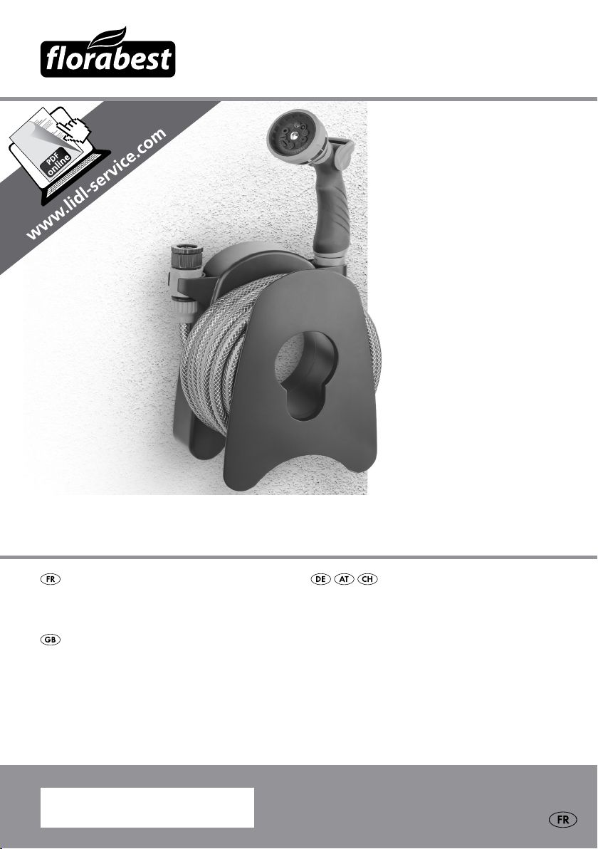
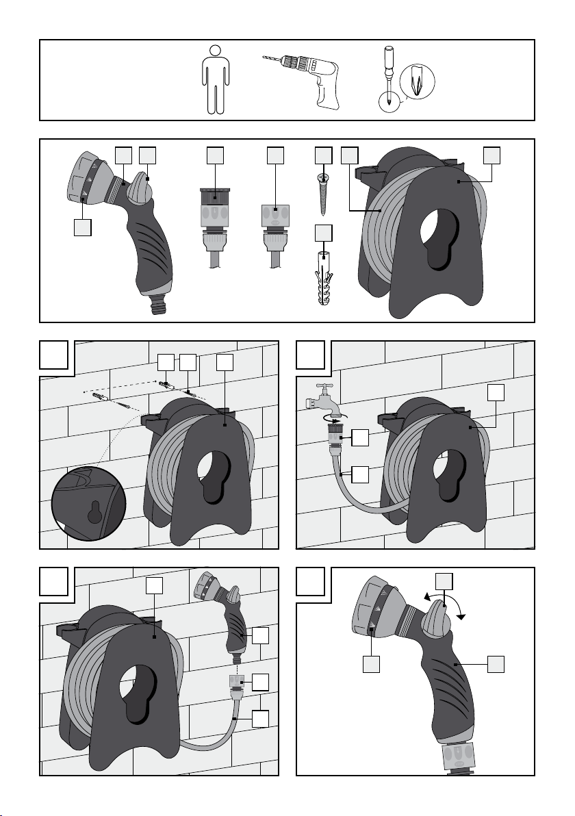
FLORABEST 280351 Installation and operating instructions
Other FLORABEST Lawn And Garden Equipment manuals

FLORABEST
FLORABEST Z30744A User manual

FLORABEST
FLORABEST 295721 User manual

FLORABEST
FLORABEST FGS 10 A1 Owner's manual

FLORABEST
FLORABEST FSTK 10 A1 User manual

FLORABEST
FLORABEST FLV 1200 B1 Owner's manual

FLORABEST
FLORABEST FHE 710 A1 Owner's manual

FLORABEST
FLORABEST FGA 20 A1 User manual

FLORABEST
FLORABEST FHV 32 A1 Owner's manual

FLORABEST
FLORABEST LAWN EDGING Technical specifications

FLORABEST
FLORABEST 315958-1904 Installation and operating instructions

FLORABEST
FLORABEST FGS 10 A1 Owner's manual

FLORABEST
FLORABEST HG00491 Installation and operating instructions

FLORABEST
FLORABEST FRP 350 B1 Owner's manual

FLORABEST
FLORABEST FHE 710 A1 Owner's manual

FLORABEST
FLORABEST GB-2784 User manual

FLORABEST
FLORABEST FLV 1200 A1 Owner's manual

FLORABEST
FLORABEST 291857 User manual

FLORABEST
FLORABEST 282463 User manual

FLORABEST
FLORABEST 282465 Installation and operating instructions

FLORABEST
FLORABEST HG04444A User manual


Popular Lawn And Garden Equipment manuals by other brands

Vertex
Vertex 1/3 HP Maintenance instructions

GHE
GHE AeroFlo 80 manual

Millcreek
Millcreek 406 Operator's manual

Land Pride
Land Pride Post Hole Diggers HD25 Operator's manual

Yazoo/Kees
Yazoo/Kees Z9 Commercial Collection System Z9A Operator's & parts manual

Premier designs
Premier designs WindGarden 26829 Assembly instructions


AQUA FLOW
AQUA FLOW PNRAD instructions

Tru-Turf
Tru-Turf RB48-11A Golf Green Roller Original instruction manual

BIOGROD
BIOGROD 730710 user manual

Land Pride
Land Pride RCF2784 Operator's manual

Makita
Makita UM110D instruction manual

BOERBOEL
BOERBOEL Standard Floating Bar Gravity Latch installation instructions