1
Cautions
Please read this manual carefully. If this desk
changes hands, please provide this manual to the
new owner.
Make sure the desk top is not touching any obsta-
cles or walls. Make sure no obstacles are in the
desk’s path. Make sure all cords are an appropriate
length to accommodate the full range of height
adjustment.
Keep children away from desk components. There
is risk of injury and electric shock.
Do not sit or stand on the desk frame. Do not crawl
or lie under the desk frame.
Do not open or modify any of the components, in-
cluding the Lifting Columns, Control Box, or Hand-
set. Doing so risks electric shock and voids any
warranty claims.
Placing objects taller than 20” underneath the desk
will obstruct the desk’s movement and may result
in physical damage.
Voltage converters
Using a voltage converter could cause damage to
the desk, and is considered improper use. Resulting
damage is not covered by the warranty.
Verify the voltage of the Control Box as labeled to
avoid damage. Alternative voltage Control Boxes
are available from Fully.
Use & liability
This Jarvis height adjustable desk has electric
motors and is designed for use in dry work environ-
ments only.
This Jarvis desk is adjustable so it can be posi-
tioned at an optimal ergonomic height. Any extra-
curricular use is at user’s own risk.
Under no circumstances does the manufacturer
accept warranty claims or liability claims for dam-
ages caused by improper use or handling of the
desk frame.
Jarvis is a registered trademark of Fully, Inc.
All rights reserved.
Before starting
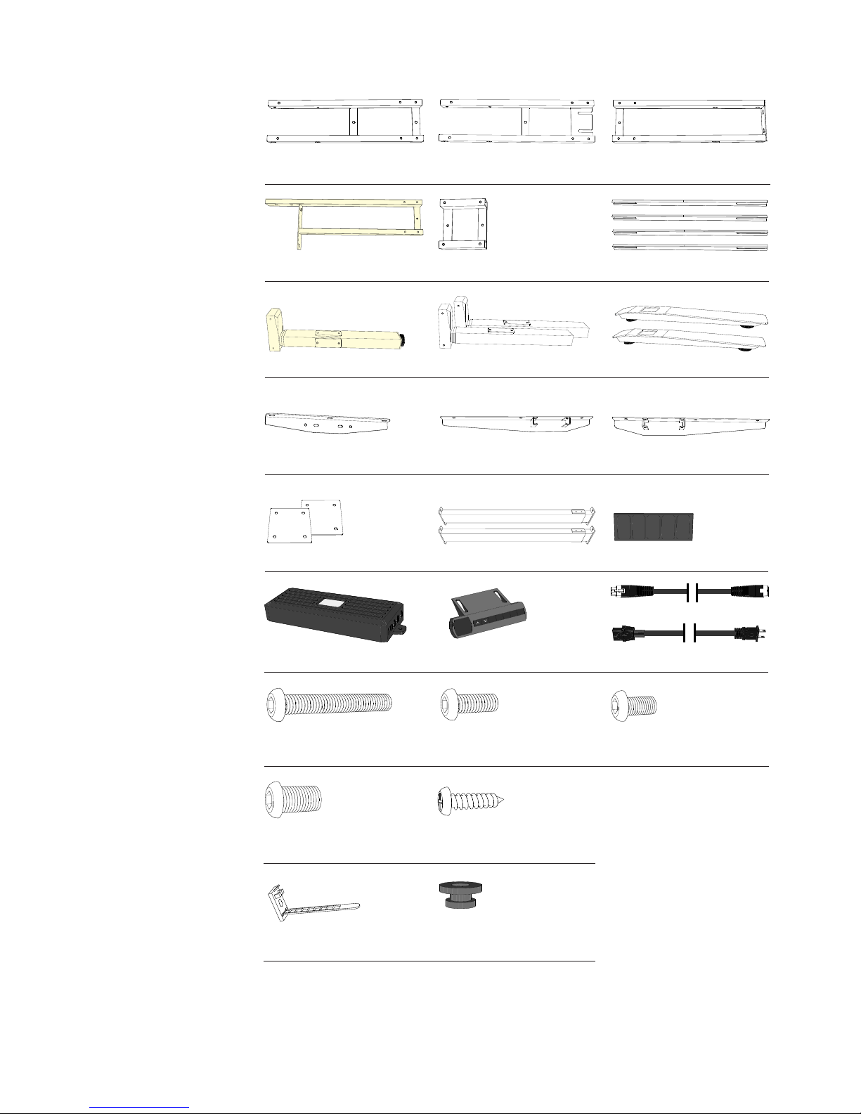
On a padded or carpeted area, take all of the items out of your Jarvis two frame boxes, and confirm that
nothing is missing. Reference the included parts listings on page 2.
Pro tip
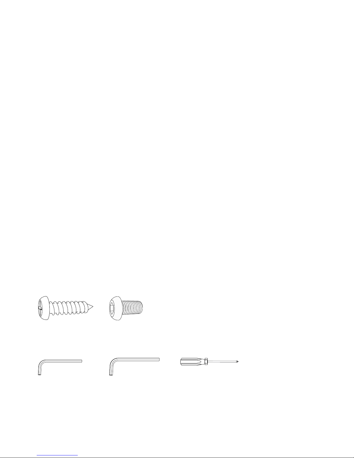
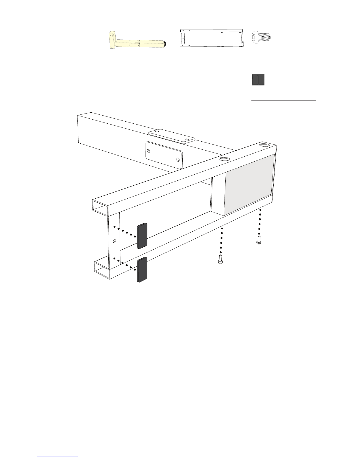
Tools
Wood Screws: Pointy End Machine Screws: Flat End
4mm Hex Wrench
(included)
5mm Hex Wrench
(included)
Phillips Head Screwdriver
(not included)