fully Jarvis User manual

Jarvis crank-powered standing desk
Assembly instructions
For assembly assistance,
call 888-508-3725
or email support@fully.com

Thank you for choosing a Jarvis desk
from Fully.

Cautions and Use
Before starting
In the box
Assembly
Using your own desk top
Laying it out
Contact
1
1
2
3
12
13
14

4mm Hex Key
6mm Wrench
Make sure the desk top is not in contact with any obstacles or walls.
Make sure all cords are an appropriate length to accommodate the full range of
height adjustment.
Do not sit or stand on the desk frame. Do not crawl or lie under the desk frame.
Do not place any objects taller than 25” underneath the desk.
Be careful to not pinch your hand when using the handle.
The desk height is adjustable so that it can be positioned at the most ergonomically
suitable height. Any other operation is at the user’s own risk.
Under no circumstances does the manufacturer accept warranty claims or liability
claims for damages caused from improper use or handling of the desk frame.
Please read this manual carefully. If this desk is resold, please provide this manual to
the new owner.
Take all of the items out on a padded or carpeted area to confirm that nothing is
missing as displayed on page 2
1
Cautions
Before starting
Tools
3mm Hex Key 2.5 mm Hex Key
#2 Phillips Screwdriver
(not included)
Jarvis is a registered trademark of Fully, LLC. All rights reserved.

Jarvis crank-powered standing desk
A— Left Lifting Column
I— Right Side Crank Rod
B— Right Lifting Column
J— Left Side Crank Rod K— Crank Sleeve
E— Right Side Bracket
M— Driving Rod
Q— Wood Screw
x12
U— Medium Set
Screw x8 (Pre-Installed)
F— Frame Ends x2
N— Adapter Plate
R—Medium Machine
Screw x16
V— Small Set
Screw x2 (Extra)
G— Center Rails x2
O— Crank Spring
S— Small Machine
Screw x4
T— Small Socket-Head
Screw x2
H— Hand Crank
P— Crank Washer x2
C— Feet x2 D— Left Side Bracket
L— Driving Rod Sleeves x2
2
W— Noise Attenuation
Grommets x5 (Extra)
Q—Desk Top Washer
x10

Assembly
Step 1
Step 2
Insert the Left Lifting Column into the Frame End as shown below.
To secure the Frame End to the Left Lifting Column, thread four (4) of the Medium
Machine Screws into the holes as shown, but do not tighten them all the way.
Once all four screws are in place, tighten completely.
Select the Left Side Bracket. The two tabs on the side bracket will slot into the
Step 1 Assembly.
Use two (2) of the Small Machine Screws to secure the Left Side Bracket. As before,
don’t tighten all the way until both screws are in place.
AF
D
A— Left Lifting Column
F— Frame End
D— Left Side Bracket
Step 1 Assembly
3
R—Medium Machine
Screw x4
S— Small Machine
Screw x2

Step 4
Lay your desk top on your padded workspace with the underside facing up, and the
front of the desk top towards you.
Place the right leg assembly (with “R” labels) on the desk top to your left, with the
frame end pointing towards you. (Once you flip your desk over, this will become the
right side, and the world will make sense again.)
B
E
F
*Front edge of
Jarvis Desk Top.
Step 3
Repeat Steps 1–2 for the Right Lifting Column, Frame End, and Side Bracket.
Desk Top Machine Screw x5
(If using own desk top)
Q— Wood Screw x5
If your Jarvis Desk Top’s pre-drilled holes have metal inserts, you will need to use
the Machine Screws packaged with the Jarvis Desk Top to secure the frame.
Otherwise use five (5) Wood Screws to attach the leg assembly to
the desk top.
4
Q—Desk Top Washer x5
Insert all five screws part way. Once they are in place, tighten them all completely.
Important

*Correct center rail orientation
Step 5
Slide the Center Rails into the frame end attached to the desk top, so that the mid-
point mark is facing up, and the cut-out slots are facing inwards.
Slide the Left Leg Assembly (with “L” labels) onto the other end of the Center Rails
(your right-hand side), and the entire frame should now fit onto the desk top.
B
E
G
Step 6
Secure the left leg assembly with the remaining screws. Insert all five screws part way.
Once they are in place, tighten them all completely.
G— Center Rails x2
Desk Top Machine Screw x5
(Included with Jarvis Desk Top)
(If using own desk top)
Q— Wood Screw x5
Q—Desk Top Washer x5
If your Jarvis Desk Top’s pre-drilled holes have metal inserts, you will need to use
the Machine Screws packaged with the Jarvis Desk Top to secure the frame.
Otherwise use five (5) Wood Screws to attach the leg assembly to the desk top.
Insert all five screws part way.
Important

Step 7
Center the labeled midpoints on both Center Rails between the two Frame Ends,
and use eight (8) of the Medium Set Screws to lock the Center Rails down firmly.
Warning
Skipping this step will
result in stability issues.
Step 8
Assemble the driveshaft by sliding the two Driving Rod Sleeves over each end of
the Driving Rod.
The sleeves have Set Screws pre-installed on both ends. Do not tighten the Set
Screws until Step 9. Make sure these Set Screws are lined up with each other and
are loose enough (as shown) to allow the Driving Rod to slide into the sleeve
completely. If the rod will not go past a setscrew, loosen the setscrew a little with
the 3mm hex key.
L— Driving Rod Sleeves x2
M— Driving Rod
Setscrew too tight
Setscrew just right
Important
L
L
M
M
L
G FF
U— Medium Set
Screw x8 (Pre-Installed)
6

Step 9
Place the assembled driveshaft between the two rod ends extending from the
Lifting Columns.
Slide the sleeves onto these rod ends completely, and make sure all Set Screws are
facing up and in line with each other as shown below.
Once the driveshaft is installed on both sides, tighten all four Set Screws to lock
them in place.
Important
Do not over tighten the Set
Screws. Stop once they make
contact with the rods and no
longer turn easily.
7
If the driveshaft does not easily line up with both rod ends you can use the
included wrench to rotate one of the rod ends into alignment as displayed in the
second image below.

Step 10
Decide whether the Hand Crank will be on the left or right side of the desk.
Right Side Hand Crank
Insert the long Crank Rod
(160mm) into the crank
socket on the Right Lifting
Column and be sure the
raised notches go inside
the leg.
Left side hand crank
Insert the short Crank Rod
(125mm) into the crank
socket on the Left Lifting
Column and be sure the
raised notches go inside
the leg.
I
Using the two (2) Wood Screws, attach the Adapter Plate making sure that the “R”
or “L” label matches your chosen orientation. If you have a Jarvis Desk Top, use the
widely-spaced pre-drilled holes for this purpose.
I—Right Side Crank Rod
B— Right Lifting Column
J— Left Side Crank Rod
A— Left Lifting Column
Q— Wood Screw x2
N— Adapter Plate
E
N
J
D
N
8
or

Step 11
Slide a Crank Washer, then the Crank Spring itself, then the second washer onto the
crank rod, as shown.
Step 12
Orient the Crank Sleeve so that its Set Screw is closest to the leg and pointing up,
and slide it onto the Crank Rod.
Slide the Hand Crank all the way into the Crank Sleeve, making sure that the pin on
the hand Crank Rod lines up with the notch in the Crank Sleeve as shown, and fit
the plastic arch-shaped crank bushing onto the Crank Sleeve.
H
K— Crank Sleeve
H— Hand Crank
P—Crank Washer x2
O— Crank Spring
K
crank bushing
Important
The Hand Crank cannot be attached
directly to the desk top!
K
P
I
O
P

Step 14
Step 13
Loosely attach the Feet to the bottom of the lifting columns with four (4) Medium
Machine Screws per foot. Once all the screws are in place, tighten them down the
rest of the way in an X pattern.
Attach the plastic crank bushing to the Adapter Plate using the two (2) Small Socket
Headscrews.
N— Adapter Plate
C— Feet x2
T
N
R
C
R
C
10
R—Medium Machine
Screw x8
T— Small Socket-Head
Screw x2

Step 15
Step 16
Double check that all screws everywhere on the desk are tight.
With a friend, lift the desk and carefully flip it onto its feet, being careful not to put
weight on the hand crank. Then adjust the pre-installed leveling glides on the feet as
needed.
Collapsable Handle
Slide and rotate the Hand
Crank under the desk for
convenient crank storage.
Please be careful not to
pinch your hand when
flipping the handle.
11

Top size limits:
Minimum: 48” x 30”
Maximum: 70” x 30”
Please use the following guidelines to properly fit your frame to your desk top, and ensure proper clearance for
the crank mechanism.
Side-to-Side Position:
In our experience, desks have the best side-to-side stability when their legs are installed as far apart as possible.
On our own Crank desk tops, we leave a one-inch overhang on each side. To achieve this, we install the Side
Bracket screws two inches from the side edge of the desk top.
Placing the holes at least 2” in from the sides lowers the chance that your desk top will split during drilling, though
this may vary depending on the material you have chosen to use.
Depending on the structural integrity of your desk top you can leave more than 1” overhanging the Side Brackets,
but an overhang of 4” is not recommended on either side.
Front-to-back position:
The front hole on the side bracket needs to be 7.25” back from the front of your desk top to fit the length of the
crank handle & mechanism.
We recommend a maximum top depth of 30”. To avoid interfering with the crank mechanism at the front, a
deeper top would add additional overhang at the back of the desk. This would compromise the desk’s center of
gravity, particularly with the addition of weight from computer monitors, etc.
Using your own desk top
12

Laying it out
The easiest way to position your own desktop on Jarvis is to partially assemble the frame and use it as a template.
This partial assembly is easier to maneuver than the entire frame and will allow you to see exactly how things line
up and where all the holes should be.
Lay your desktop on a padded workspace with the underside facing up and the front of the desk top towards you.
Without the Lifting Columns, attach the Side Brackets to the Frame Ends as shown in Steps 2 and 3 on page 3
and 4.
Slide the Center Rails into the Frame Ends. Position the frame assembly on the underside of your desk top, with
the screw holes in the Side Brackets 2-5” from the edges of the top (leaving 1-4” of overhang). The front Side
Bracket screw hole should be 7.25” from the front (user-facing) edge of the desk top.
The example below shows a 30” x 56” desktop with the frame assembly correctly positioned:
We now know where all the frame screws need to be placed. Indent the center point of each hole with the tip of a
Phillips-head screwdriver— this is more accurate and permanent than using a marker or pencil.
13

Next, position the adapter plate 1” back from the front of the desk top, and X.3” from the side of the top, where X
is the inches of top overhang. e.g.
1” of overhang: plate should be 1.3” from the side of the desk top
2” of overhang: plate should be 2.3” from the side of the desk top
3” of overhang: plate should be 3.3” from the side of the desk top
4” of overhang: plate should be 4.3” from the side of the desk top
Refer to Step 10 (Page “8”)for proper adapter plate orientation. The illustration below shows a right-hand crank
assembly, with 1” of top overhang.
Indent the center point of
each hole with the tip of a
Phillips-head screwdriver,
as before. Disassemble
the frame components
and return to the standard
assembly instructions on
page 3.
14
Contact
Fully
Portland, Oregon
888-508-3725
support@fully.com
www.fully.com

Desk, chairs & things to
keep you moving
90.014.01.0499 v.G
Other manuals for Jarvis
12
Table of contents
Other fully Indoor Furnishing manuals

fully
fully Jarvis User manual

fully
fully Sidekick User manual

fully
fully Balans User manual

fully
fully Jarvis User manual

fully
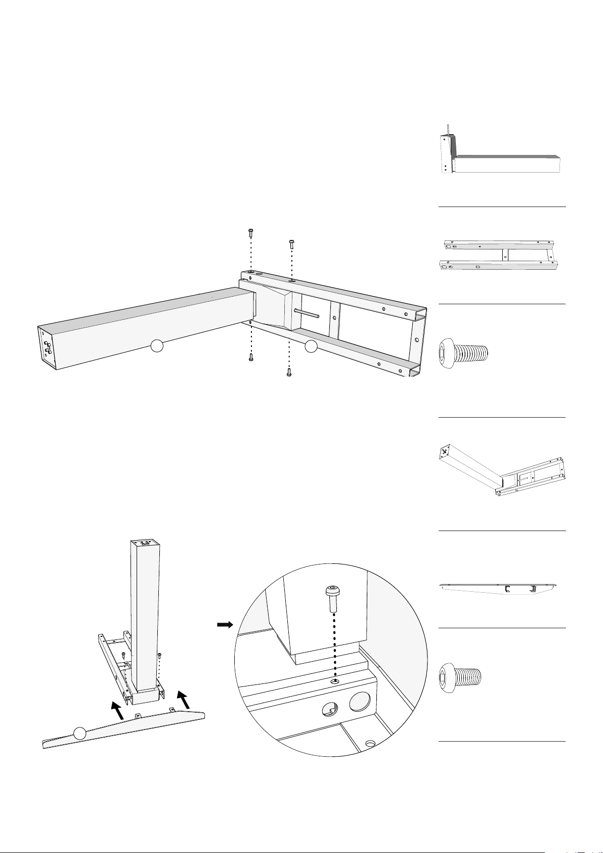
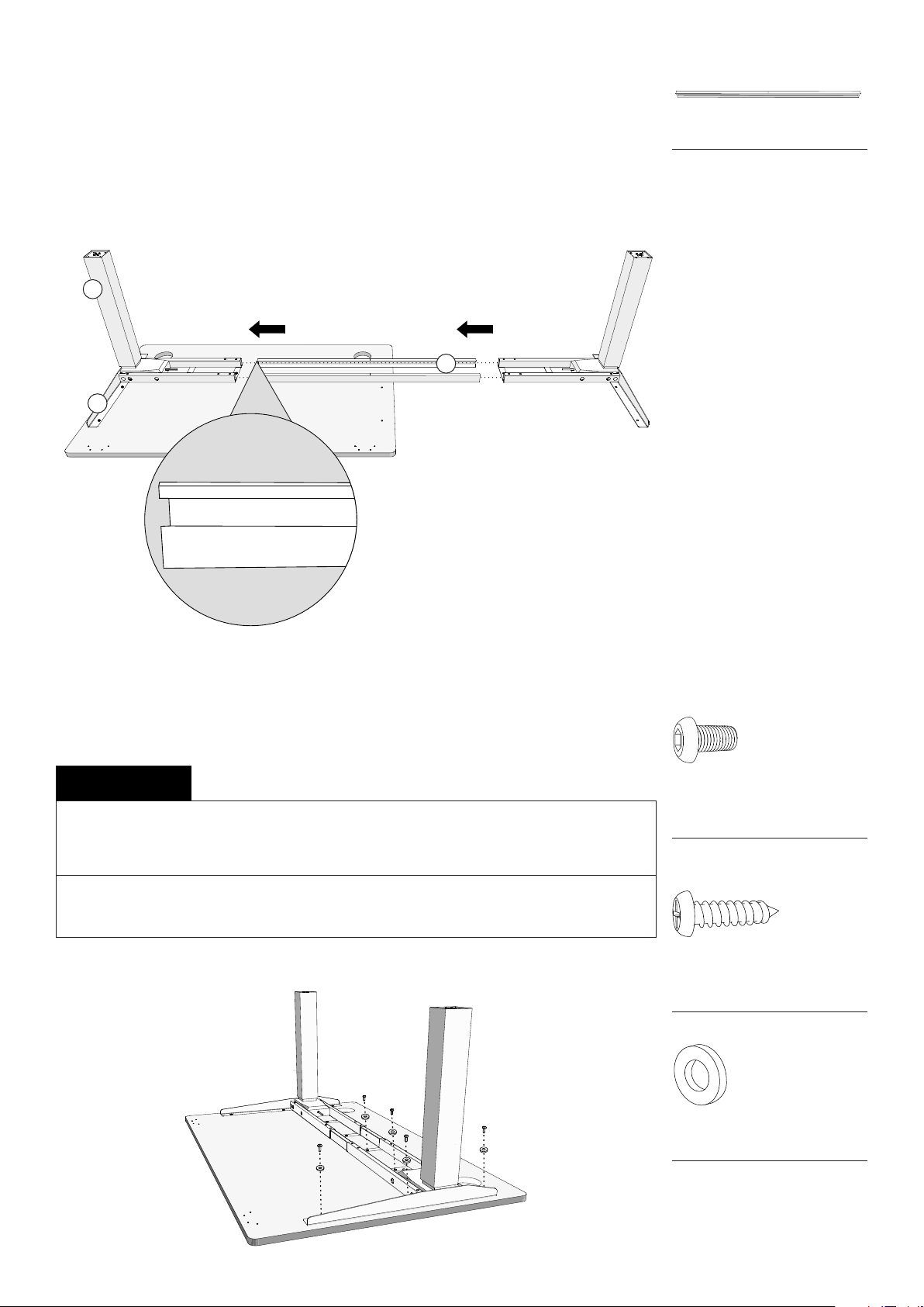
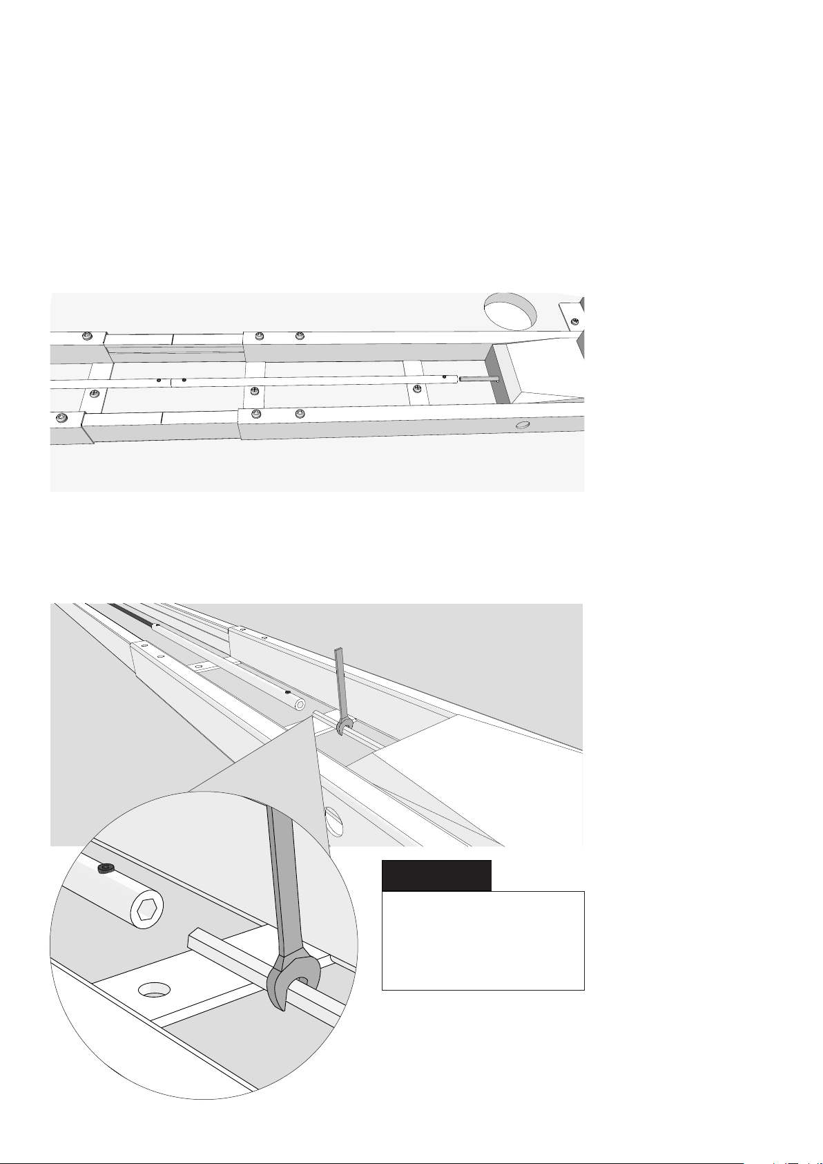
fully Jarvis L-shaped standing desk User manual

fully
fully Jarvis User manual

fully
fully Jarvis User manual

fully
fully Remi User manual

fully
fully Remi User manual

fully
fully Nolan User manual
Popular Indoor Furnishing manuals by other brands

Hooker Furniture
Hooker Furniture 500-50-828 Assembly instruction

Julian Bowen Limited
Julian Bowen Limited Coxmoor Assembly instructions

SHANGRI-LA
SHANGRI-LA SERENGETI SLSERENDCWA user guide

Wholesale Interiors
Wholesale Interiors 4810 Assembly instructions

OVE
OVE RIDER 48 installation manual

Plymold
Plymold Z000000453 installation manual