manuals.online logo
Brands
  1. Home
  2. •
  3. Brands
  4. •
  5. GE
  6. •
  7. Circuit Breaker
  8. •
  9. GE Spectra K-frame User manual

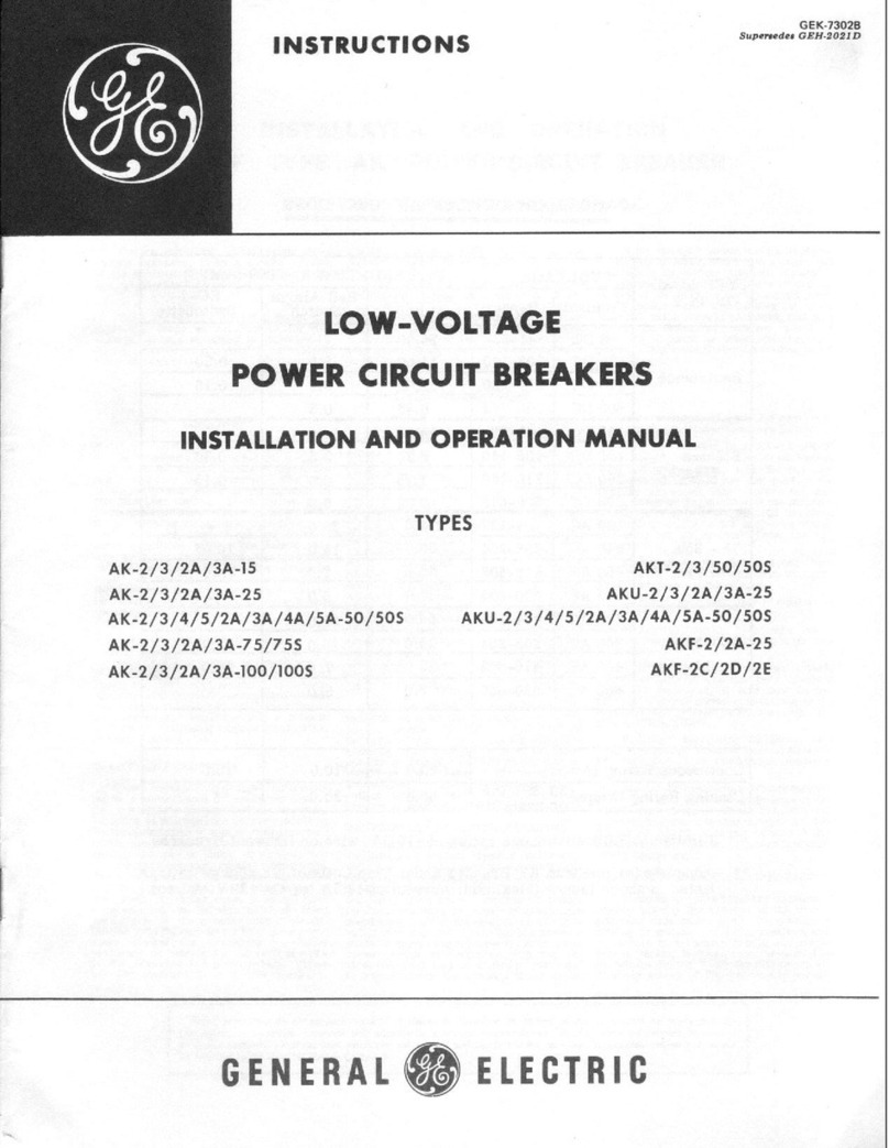
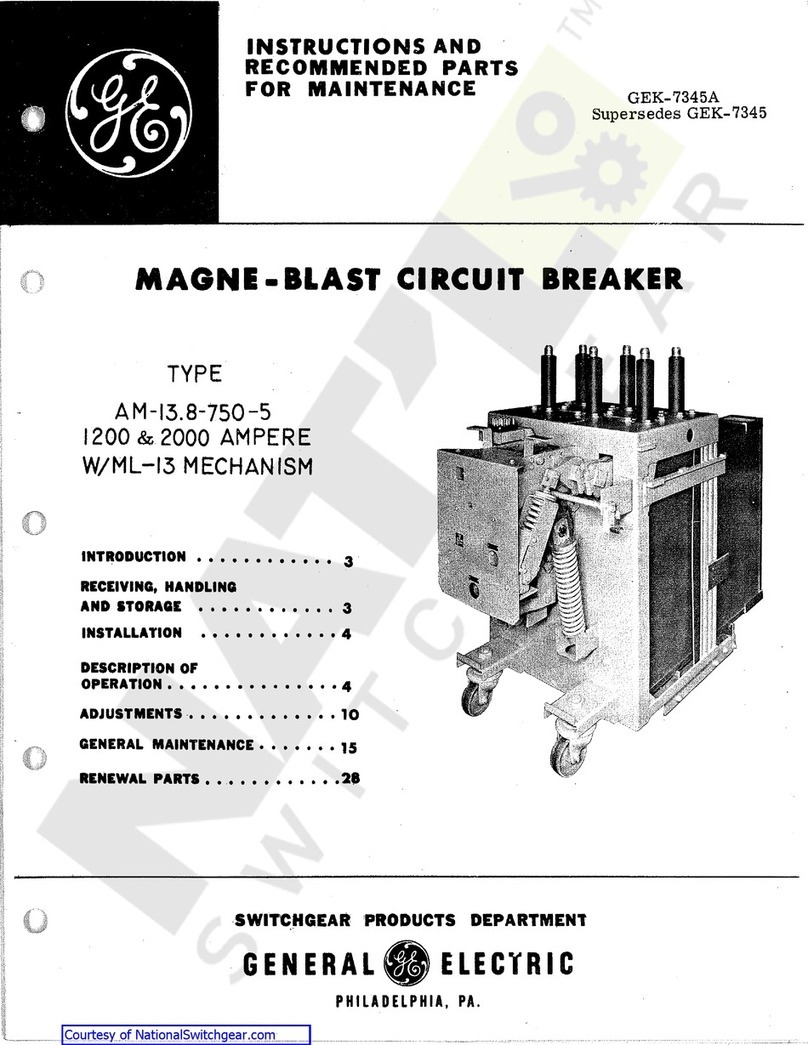
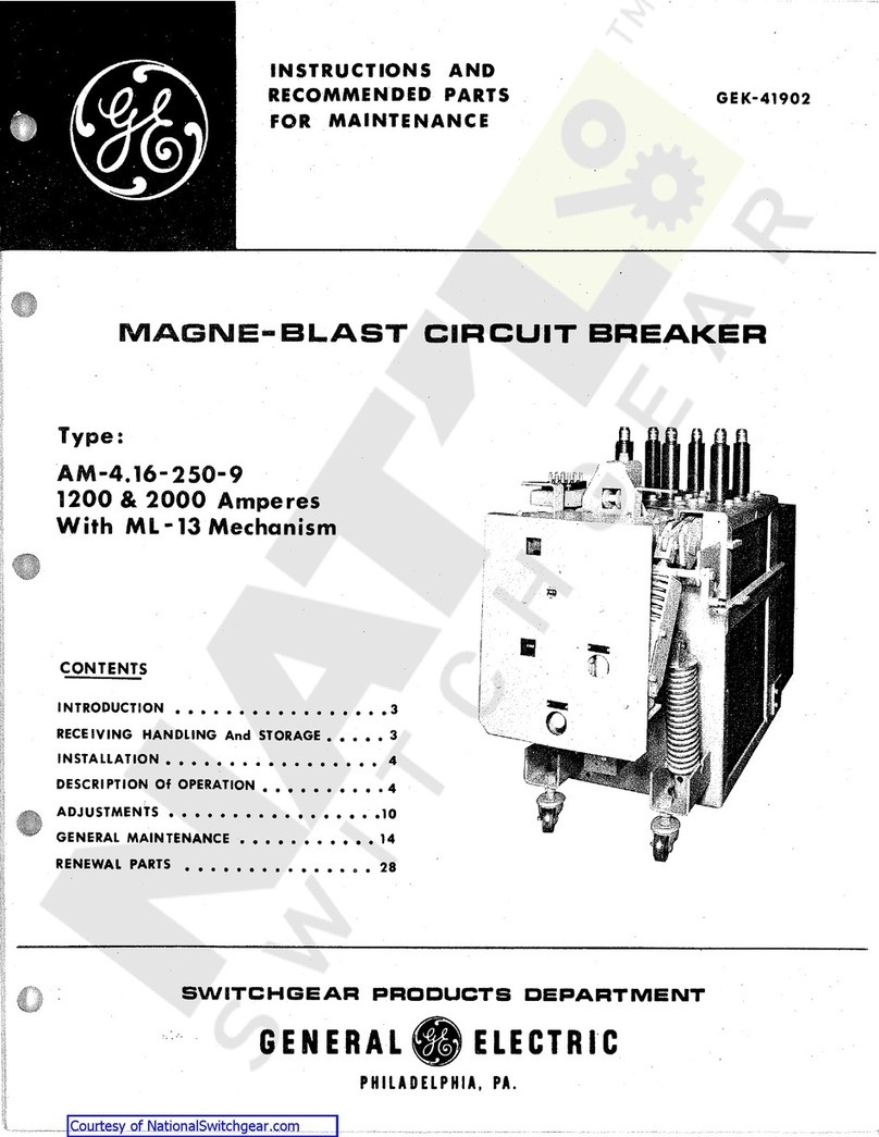
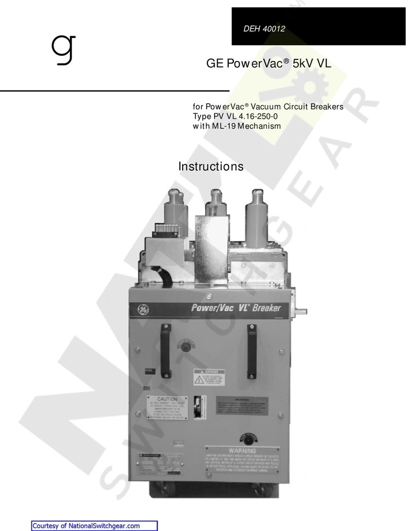
GE Spectra K-frame User manual

1
INSTALLATION INSTRUCTIONS
Retrofit of Spectra K-frame with ABB Tmax XT7 breaker
Single Mount (Bolt-On kits)
General
These instructions are applicable to retrofit of Spectra K-frame with ABB Tmax XT7 breaker.
Table 1 lists the parts included in the bolt-on circuit breaker kits for single branch configurations.
WARNING
Danger of electrical shock or injury. Turn OFF power ahead of the panel board or switchboard before working inside the equipment
or removing any component. Equipment is to be installed and maintained by properly trained and qualified personnel only.
Installation
Numbers in brackets in the following instructions and figures refer to the item numbers in table below.
Item Part Description Qty.
  
  
  
Breaker mounting bracket 
  
  
  
L-Shaped Barrier 
Filler plate 
 Busbar Link assembly - C phase 
Item Part Description Qty.
 Busbar Link assembly - B phase 
 Busbar Link assembly - A phase 
 
application) 
  
Item Part Description
Torque wrench
—
Retrofit Kit
—
Required Tools
Below listed tools are required for installation
—
Table 1. Retrofit kit
STEP 2

tighten the screw.
—
Figure 2. Install foldable handle assembly
STEP 4
Install the strap assemblies [10,11,12] with the corresponding
holes in the vertical bus, as shown in Figure 4. Fasten each strap
assembly loosely to the vertical bus with two carriage bolts [1],

Main Bus
 

 
  

REF
LINE LOAD
Cable entry

Remove flat cap and screw
Install foldable handle assy


—
Figure 6. Prepare L-shaped barrier assembly
—
Figure 5. Installation of mounting bracket
STEP 5
Install the breaker mounting bracket [4] to the panel side rail with

figure 5.
STEP 6

-
plied with breaker kit) to the adhesive surface of L shape barrier




Folded
Breaker side
Adhesive side
Align holes
Breaker isolation
backplate
To mate with
mounting plate
2
STEP 1
Prepare the breaker, install required lugs and identify the re-
quired mounting and termination accessories from circuit
breaker kit. Refer to breaker instruction document for more infor-
mation.
—
Figure 1. Prepare the breaker
STEP 3
Find the side of the panel interior at which the dimension from
the face of nearest vertical bus to the inner face of the bus sup-

—

—
Figure 4. Installation of link assy. A, B & C phase

—

—
Figure 7c. Flange nut
STEP 7 Continued STEP 8
-
sembly) at the vertical bus to 65 lb-in. It may be necessary to re-
move adjacent circuit breaker modules to allow access to the
bolted connections at the vertical bus.


 
3
STEP 7 Continued
—
Figure 7b. Socket head screw
STEP 7
Install breaker with L-shaped barrier assembly [from STEP 6].
Refer figure 7a. Tighten Socket head screw [7] and flange nut [6],
torque the screw [7] to 22 lb-in. Torque the flange Nut [6] to 160
lb-in. Refer figure 7b and 7c.
—
Figure 7a. Installation of breaker and L shaped barrier assembly


L-shaped barrier with
isolation base plate


STEP 10
Install the filler plate [9] to panel with thread forming screw [5],

—
Figure 10. Install filler plate
STEP 9
-
plied screws as shown in figure 9.
—
Figure 9. Install terminal cover
  
—
Figure 11b. Install the kirk lock
—
Figure 11a. Kirk lock mounting kit assembly
STEP 11 Continued


set to the installed on the panel XT7 filler plate with Thread form-

STEP 11: Optional - Kirk lock mounting kit assembly
Pre-assemble Kirk lock mounting kit assembly as shown in figure
11a.
Note: Kirk-lock is not included in the kit. Re-use Kirk lock from
panel.



Kirk lock block with key




Thread forming

Documentation Number: DET 1054
4
—
ABB Inc.
305 Gregson Drive
Cary, NC 27511
—
We reserve the right to make technical
changes or modify the contents of this doc-
ument without prior notice. With regard to
purchase orders, the agreed particulars
shall prevail. ABB AG does not accept any re-
sponsibility whatsoever for potential errors
or possible lack of information in this docu-
ment.
abb.com
We reserve all rights in this document and in
the subject matter and illustrations con-
tained therein. Any reproduction, disclosure
to third parties or utilization of its contents
– in whole or in parts – is forbidden without
prior written consent of ABB AG. Copy-
right© 2019 ABB
All rights reserved
Disclaimer : These instructions do not cover all details or variations in equipment nor do they provide for every possible contingency that may be met in connection with installation, operation
or maintenance. Should further information be desired or should particular problems arise that are not covered sufficiently for the purchaser's purposes, the matter should be referred to the
ABB Company.
GE logo is licensed by General
Electric Company to ABB

Other GE Circuit Breaker manuals

GE AM-13.8-500-7 User manual

GE

GE AM-13.8-500-7 User manual

GE Power Break II User manual

GE

GE Power Break II User manual

GE Spectra Series User manual

GE

GE Spectra Series User manual

GE AK-1-15 Series User manual

GE

GE AK-1-15 Series User manual

GE SD200SA User manual

GE

GE SD200SA User manual

GE MicroVersaTripPlus AK-50 User manual

GE

GE MicroVersaTripPlus AK-50 User manual

GE PowerVac GEK-86132F User manual

GE

GE PowerVac GEK-86132F User manual

GE GL 310 F1/4031 P/VR User manual

GE

GE GL 310 F1/4031 P/VR User manual

GE Spectra Series AMC3FGB User manual

GE

GE Spectra Series AMC3FGB User manual

GE Power Break II User manual

GE

GE Power Break II User manual

GE SPRCS024 User manual

GE

GE SPRCS024 User manual

GE MicroVersa Trip Plus User manual

GE

GE MicroVersa Trip Plus User manual

GE EntelliGuard G User manual

GE

GE EntelliGuard G User manual

GE Rapid TripFix User manual

GE

GE Rapid TripFix User manual

GE AKR-30 Series User manual

GE

GE AKR-30 Series User manual

GE M-Pact Plus User manual

GE

GE M-Pact Plus User manual

GE FASHT Series User manual

GE

GE FASHT Series User manual

GE CB Watch 3 User manual

GE

GE CB Watch 3 User manual

GE MicroVersaTrip Plus User manual

GE

GE MicroVersaTrip Plus User manual

GE AKR-75 Series Programming manual

GE

GE AKR-75 Series Programming manual

GE AKR Series Configuration guide

GE

GE AKR Series Configuration guide

GE MicroVersaTrip AKR-75 User manual

GE

GE MicroVersaTrip AKR-75 User manual

GE ML-14-0 User manual

GE

GE ML-14-0 User manual

GE EntelliGuard G User guide

GE

GE EntelliGuard G User guide

Popular Circuit Breaker manuals by other brands

Siemens SINAMICS S120 operating instructions

Siemens

Siemens SINAMICS S120 operating instructions

Siemens CDT3A Series operating instructions

Siemens

Siemens CDT3A Series operating instructions

Eaton Power Defense IZMX16 Instruction leaflet

Eaton

Eaton Power Defense IZMX16 Instruction leaflet

Siemens 3VS16 operating instructions

Siemens

Siemens 3VS16 operating instructions

Alstom GL317X instruction manual

Alstom

Alstom GL317X instruction manual

ABB HD4/R Installation and service instructions

ABB

ABB HD4/R Installation and service instructions

Eaton ZP-IHK installation instructions

Eaton

Eaton ZP-IHK installation instructions

CHINT NRE8 Series User instruction

CHINT

CHINT NRE8 Series User instruction

ABB Tmax T7 Installation directions

ABB

ABB Tmax T7 Installation directions

ABB SACE Emax E2.2 Installation, operation and maintenance instructions for the installer and the user

ABB

ABB SACE Emax E2.2 Installation, operation and maintenance instructions for the installer and the user

Votronic RCBO 16-30 Mini Installation and operating manual

Votronic

Votronic RCBO 16-30 Mini Installation and operating manual

nader NDM3E Series product manual

nader

nader NDM3E Series product manual

Eaton CI-PKZ01 Series Instruction leaflet

Eaton

Eaton CI-PKZ01 Series Instruction leaflet

Siemens WL Series Selection and Application Guidelines

Siemens

Siemens WL Series Selection and Application Guidelines

WEG DWB800 installation instructions

WEG

WEG DWB800 installation instructions

Allis-Chalmers LA-600 Instruction book

Allis-Chalmers

Allis-Chalmers LA-600 Instruction book

Siemens 814913A Instructions for installation

Siemens

Siemens 814913A Instructions for installation

ABB Vmax manual

ABB

ABB Vmax manual

manuals.online logo
manuals.online logoBrands
  • About & Mission
  • Contact us
  • Privacy Policy
  • Terms and Conditions

Copyright 2025 Manuals.Online. All Rights Reserved.