A converter kit with short air-in hoses is included to convert between male and female
connections. It should be used to connect air from WAVE Cabinet to WAVE instruments.
Remove the short air-in hoses when no WAVE instrument is connected, otherwise the
hose will be open.
Electrical connections
WARNING
Protective ground. The WAVE Cabinet must always be connected
to a grounded power outlet.
WARNING
Access to power switch and power cord. The power switch must
always be easy to disconnect. The power cord must always be
easy to disconnect.
WARNING
Disconnect power. Always disconnect power from the instrument
before performing any installation or maintenance task.
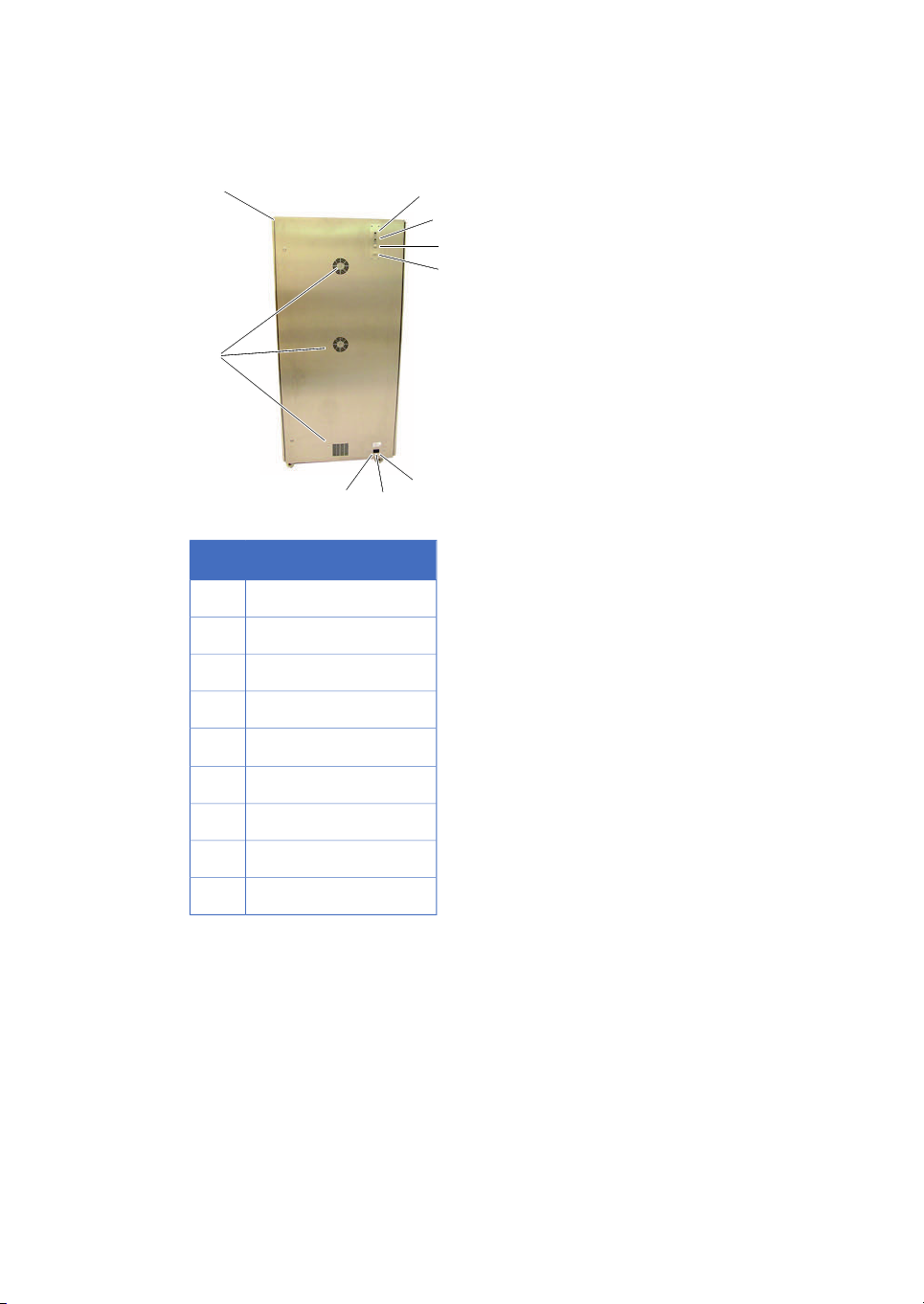
The main switch is located in the lower right corner seen from the back. This switch is
small and can easily be overseen. If the cabinet appears to be out of power even when
the mains cable is connected to live power, check this switch. If it is still out of power,
see Changing fuse, on page 20.
Computer connections
Ethernet can only be connected to one control unit as delivered. To connect several
control units, an Ethernet switch or router is required. This must be provided by the
customer.
The dataport (serial port, Modbus) can be connected to several WAVE instruments in
series, for further information see the manual for the respective instrument.
WAVE Cabinet 20/50 User Manual 28-9651-86 AA 9
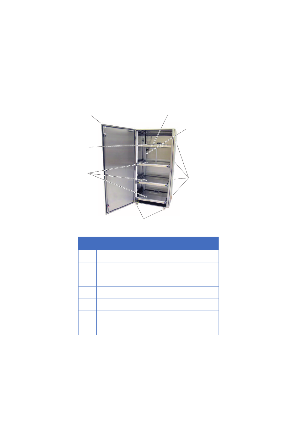
2 Product description