GE akta start Guide

ÄKTA™start
Maintenance Cue Card
Contents
System overview 2
Flow path overview 4
Regular maintenance 4
Cleaning system ow path 5
Clean the column 7
Other maintenance procedures 7
Storage of the instrument 11
Safety precautions 11
Getting help 12
Reference information 12
Overview
ÄKTA start is a simple and modern liquid chromatography system intended for
preparative purication of proteins at laboratory scale. The system can be used for
a variety of research purposes to fulll the needs of the users in the academia and in
the life sciences industry.
The Maintenance Cue Card describes the maintenance schedule for ÄKTA start and
Frac30 (the Fraction collector), and provides instructions for routine maintenance.
Regular maintenance is important for safe and trouble-free operation of ÄKTA start.

ÄKTA start Maintenance Cue Card, 29-0240-43 AC 2
System overview
Main features of ÄKTA start
ÄKTA start is operated in two modes: 1) using Instrument
Display (touch screen), and 2) using UNICORN start.
ÄKTA start is oered with a dedicated Fraction collector,
Frac30.
Quick start methods available for easy purication of
common tagged/untagged proteins.
Method templates available for Anity Chromatography
(AC), Ion Exchange Chromatography (IEX), Gel Filtration
(GF) and Desalting (DS).
Predened methods available for cleaning the system
ow path, ow cells (UV and Conductivity) and testing the
system performance.
Instrument Display - home screen
•
•
•
•
•
Instrument illustration
The illustration below shows the locations of the modules
placed on the wet side of the instrument. The modules
have the following functions:
To deliver the liquid in the system ow path and divert
the ow as required
To monitor the UV absorbance and conductivity of the
liquid
•
•
1
2
3
4 5
6
7
8 9 10
Part Description
1 ÄKTA start
2 Frac30, Fraction collector
3 PC with UNICORN™ start software
Part Description Part Description
1Buer valve 6Wash valve
2Mixer 7Injection valve
3Sample valve 8UV Monitor
4Pump 9Conductivity Monitor
5Pressure sensor 10 Outlet valve
1 23
The ÄKTA start home screen displays four options for the
user to select and perform operations from.
Method run:run predened methods
Manual run: start and control the system in real time
Create method: create, edit, import and delete methods
Settings and service: congure, calibrate, troubleshoot
and diagnose modules

ÄKTA start Maintenance Cue Card, 29-0240-43 AC 3
Frac30 , Fraction collector
1
2
3
4
5
6
Part Description Part Description
1 Dispenser arm 4 Bowl assembly
2Tubing holder 5 Base unit
3Collection tubes 6 Power indicator
UNICORN start overview
UNICORN start is a software package for:
Controlling the ÄKTA start instrument•
Creating and editing methods•
Evaluating and analyzing the results from ÄKTA start•
Module Features
System
Control
Provides an intuitive and easy-to-use
interface to control ÄKTA start.
Performs and monitors manual
chromatography runs.
Performs and monitors automated
predened or user dened chromatography
method runs.
Performs system performance method runs.
Method
Editor
Provides the exibility to automate the
chromatography runs.
Allows creation of methods from predened
chromatography templates like Anity, Gel
Filtration, Ion Exchange and Desalting.
Gives exibility to create a customized
method by dragging and dropping the
chromatography phases such as Prime and
Equilibration, Sample Application, Elution
and Fractionation, etc.
Allows exporting methods to a USB ash
drive for importing them into ÄKTA start.
Evaluation Allows viewing and presentation of results,
including creation of PDF reports.
Allows various evaluation operations on
curves and chromatograms including
comparison, peak integration etc.
Allows importing results from ÄKTA start and
exporting results to other formats.
Adminis-
tration
Allows administration of the UNICORN start
database for backup, restore, archive and
retrieve operations.
Allows reviewing of UNICORN start and
system logs.
Safety
Read ÄKTA start Operating Instructions
before using the instrument.

ÄKTA start Maintenance Cue Card, 29-0240-43 AC
4
Flow path overview
The illustration below shows the ow path for ÄKTA start.
Part Description Part Description Part Description
1Buer valve 5Pressure sensor 9UV Monitor
2Mixer 6Wash valve 10 Conductivity Monitor
3Sample valve 7Injection valve (manual) 11 Outlet valve
4Pump 8 Column 12 Fraction collector
Regular maintenance
Regular maintenance is important for safe and trouble-
free operation of ÄKTA start. The user should perform
maintenance on a daily, weekly and monthly basis.
Periodic maintenance schedule
The periodic maintenance schedule provides a guide to
the user to ensure proper maintenance of the ÄKTA start
and Frac30.
Interval Maintenance action
Daily Visually inspect the instrument for leakages
in the ow path.
If there are signs of liquid leaking, check
integrity of tubing and tubing connections.
Clean the column and ow path after use
and leave the system lled with DM water.
Note: If the instrument is not going to be used
for 1-2 days, prepare the system for storage.
Note: Open the pump cover after switching
o the instrument.
Interval Maintenance action
Weekly,
or when
required
Visually inspect the inlet lters and clean
them if necessary.
Cleaning procedure: immerse and leave the
inlet lters in 1 M NaOH for about 2 hours.
Clean the system ow path with 0.5-1 M
NaOH and rinse with demineralized (DM)
water.
Note: Do not leave the system in NaOH for
more than 20 min.
Note: Cleaning may be necessary more or
less frequently, depending on the system
usage and the nature of the samples.
Calibrate the Pump.
When
required
Clean the instrument externally.
Cleaning procedure: Wipe the surface with
a damp cloth. Wipe o stains using a mild
cleaning agent or 20% ethanol.

ÄKTA start Maintenance Cue Card, 29-0240-43 AC 5
Cleaning system ow path
Purpose
The system methods are used for cleaning the system ow
path, including all the inlets and outlets. The following wash
methods are available:
Pump wash A, Pump wash B
Washout fractionation tubing
System cleaning
Pump wash A/B
The Pump wash method is used to wash the selected
inlets/outlets and ow path tubing at high ow rate using
the specied buer port. Pump wash prevents cross-
contamination and carryover of buers/samples.
The Pump wash method is recommended:
Before starting a run when the system is not in use for a
prolonged period of time
When changing buers
Instruction
Immerse the buer Aor B inlet tubing in DM water or
buer of choice.
Follow the workow below to run Pump wash.
Operation from the Instrument Display
Perform the following operations to run Pump wash.
•
•
•
•
•
1.
2.
Select
method
Method run
Prepare system
Pump wash A
End
Run
Exit
Pump wash B
Immerse
inlet A
in Buffer A
Immerse
inlet B
in Buffer B
ÄKTA start
Interval Maintenance action
When
required
Clean the Fraction collector.
Note: Frac30 is not a spill-free design. There
will be some spillage when tubes shift
position, depending on the ow rate.
Perform System cleaning, Pump Wash A
and B, Washout Fractionation tubing.
Clean the UV ow cell.
Clean the Conductivity cell.
Calibrate UV.
Calibrate Conductivity.
Perform Zero oset for the Pressure sensor.
Replace the inlet lters.
Replace the tubing and connectors.
Yearly,
or when
required
Check the drive sleeve on the Fraction
collector. Replace if worn out.
Operation from UNICORN start
Perform the following operations to run Pump wash.
UNICORN start
Method run
System control
Pre defined
System preparation
Pump wash A /
Pump wash B
Washout fractionation tubing
The Washout fractionation tubing method is used
to clean the fractionation tubing. The method is
recommended:
Before collecting the fractions using the Outlet valve
without Fraction collector
When changing buers
•
•
Instruction
Immerse the buer inlet tubing in DM water or the
buer of choice.
Disconnect the column from the ow path and
reconnect the tubing with a Union connector.
Follow the workow below to run Washout
fractionation tubing.
1.
2.
3.

ÄKTA start Maintenance Cue Card, 29-0240-43 AC 6
Operation from the Instrument Display
Perform the following operations to run Washout
fractionation tubing.
Method run
Prepare system
Washout fractionation
tubing
EndRun
Exit
Edit run
Set Run parameters to
suit your requirement
ÄKTA start
Operation from UNICORN start
Perform the following operations to run Washout
fractionation tubing.
UNICORN start
Method run
System control
Pre defined
System preparation
Washout fractionation
tubing
System cleaning
The System cleaning method is used to clean the
instrument ow path. The method is recommended for:
Routine maintenance
Preparing the system for storage
Removing/preventing contamination (bacterial growth)
in the ow path
Preventing carryover of buers/samples
Cleaning solutions
1 M NaOH
DM water
•
•
•
•
•
•
Instruction
Clean the inlets and outlets (buer tubing, sample inlet
tubing, fractionation tubing)
Immerse the buer inlet tubing (A & B) in 1 M NaOH.
Disconnect column from the ow path and reconnect
the tubing with a Union connector.
Follow the workow below to run System cleaning.
1.
2.
3.
4.
Note:
Do not leave NaOH in the system. Wash the ow path
with water thoroughly.
Check the pH after water wash to ensure complete
removal of NaOH.
It is recommended not to end the method prior to its
completion.
•
•
•
Operation from the Instrument Display
Method run
Prepare system
Follow the instructions
& tap Continue
Run ended
Exit
System cleaning
When prompted, immerse the
buffer inlets (A & B) in DM water
Continue
ÄKTA start
Operation from UNICORN start
UNICORN start
Method run
System control
Pre defined
System preparation
System cleaning

ÄKTA start Maintenance Cue Card, 29-0240-43 AC 7
Instruction
Disconnect the tubing from the top of the UV ow
cell, and replace the ngertight connector with a
Luer connector* (needed for connecting a syringe).
Disconnect the tubing from the bottom of the UV
ow cell, connect a piece of tubing of sucient
length to the UV ow cell and insert the tubing into a
waste container.
Fill a syringe with detergent solution and inject the
detergent solution through the UV ow cell about
ve times.
Leave the UV ow cell lled with cleaning solution for
15 minutes.
Fill a syringe with DM water and rinse the ow cell
thoroughly.
1.
2.
3.
4.
5.
Clean the Conductivity ow cell
Maintenance interval
Clean the Conductivity ow cell when the Conductivity
Monitor shows a slow response or when the conductivity
measurements are not comparable to previous results.
Cleaning solutions
1 M NaOH
DM water
Note: Before cleaning the Conductivity cell, remove the
column from the ow path and re-connect the ow path.
•
•
Instruction
Immerse the inlet tubing (either A or B) in 1M NaOH.
Start a manual run and pump 1M NaOH at 1 ml/min
through the ow cell for 10 minutes.
Pause the run. Leave the Conductivity ow cell lled
with 1M NaOH for 15 minutes.
Immerse the inlet tubing in DM water.
Resume the run and rinse the ow cell thoroughly.
1.
2.
3.
4.
5.
Clean the column
Cleaning
After a run is completed, clean the column if required.
Instruction
Disconnect the column from the ow path
Clean the column o-line according to the column
instructions.
Storage
If the column is not going to be used for a couple of days
or longer, store the column.
Instruction
Fill the column with the storage solution recommended
in the column data sheet.
Detach the column from the instrument and store it
according to the column recommendation.
•
•
•
•
* Luer connectors are a type of ttings used for making
leak-free connections by interlocking the counter-parts
(male and female connectors).
Note:
Do not leave NaOH for a very long time in ow cell
to avoid damage. Rinse the ow path with water
thoroughly.
Make sure that the NaOH is completely removed. The
conductivity reading in the Run view screen should be
less than 1 mS/cm.
•
•
Calibrate the Instrument Display
Calibrate the Instrument Display if there are any issues
with the response of the touch screen.
Instruction
In the ÄKTA start home screen, tap Settings and
service to access the instrument modules.
Tap Display to access the touch screen options.
In the Display screen, tap Touch screen calibration to
start the calibration.
In the four subsequent calibration screens, tap on the
marked circles, as requested.
1.
2.
3.
4.
Pressure sensor zero oset
The pressure is set as 0 with the Pressure sensor exposed
to atmospheric pressure only (Zero oset).
P set parameter displays the pressure in the ow path.
Other maintenance
procedures
Clean the UV ow cell
Maintenance interval
Clean the UV ow cell once every three months, or when
the signal is unstable or readings appear to be incorrect.
Cleaning solutions
10% surfactant detergent solution (e.g., Decon™ 90,
Deconex™ 11, or RBS 25)
DM water
•
•

ÄKTA start Maintenance Cue Card, 29-0240-43 AC 8
Calibrate the Pump
For detailed instructions, refer to ÄKTA start Maintenance
Manual.
Instruction
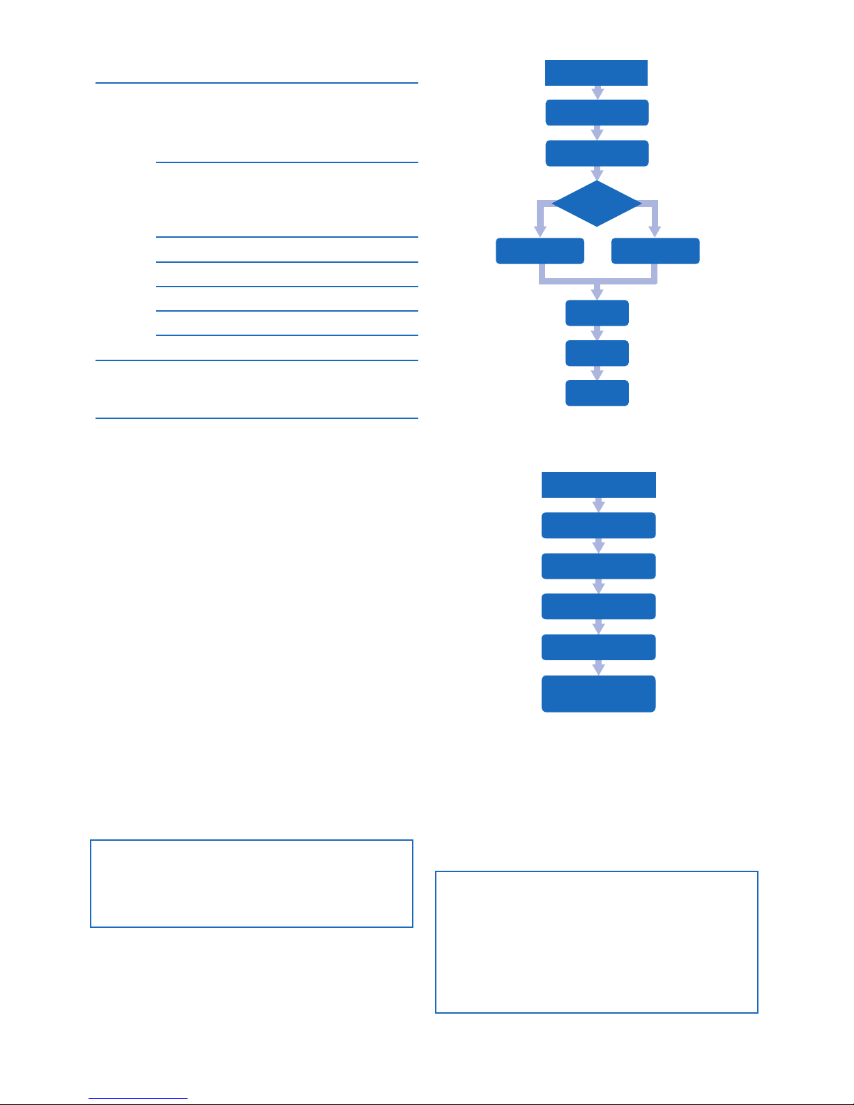
Immerse the buer inlet tubing A in DM water.
Place the outlet tubing from the Wash valve in a pre-
weighed collection tube.
In the Settings and service screen, tap Pump to access
the Pump options, then tap Calibration.
Set the intended ow rate in the range 0.5 to 5 ml/min.
Tap Start ow to start the Pump and collect water for
at least one minute in the pre-weighed collection tube.
Measure exactly the volume of the water collected,
then set Collected volume value equal to this volume.
Tap Calibrate to carry out the calibration.
1.
2.
3.
4.
5.
6.
7.
Calibrate the UV Monitor
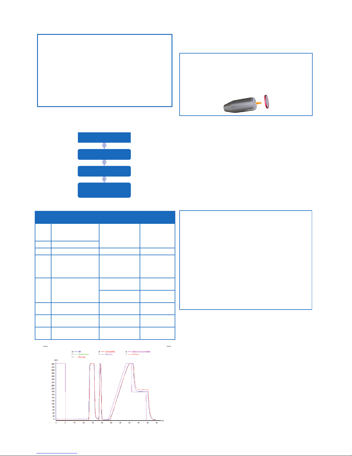
Set the ow cell path length
If the UV ow cell was replaced, a new cell path length
value has to be set.
Instruction
In the Settings and service screen, tap UV to access
the UV Monitor options.
In the UV screen, tap Flow cell path length.
Set the cell path length, Cell, corresponding to the new
UV ow cell.
Tap Save path length to save the value.
Note: The Cell path length is provided on the packing of
the UV ow cell. If the ow cell path length is not available,
refer to Operating Instructions for instructions to calculate
the Cell path length.
Calibrate the UV LED
Note: Make sure that the UV ow cell is assembled tightly,
and the inlet and outlet tubes are tted tightly to the UV
Monitor. No stray light should enter the UV Monitor.
1.
2.
3.
4.
Calibrate the Conductivity Monitor
Set the cell constant value
Instruction
In the Settings and service screen, access
Conductivity > Conguration.
Set the cell constant value for the new Conductivity
ow cell and tap Save to save the new value.
Note: The cell constant value is provided on the packaging
of the Conductivity ow cell. If a cell constant value is not
available, calibrate the Conductivity ow cell as explained
in the ÄKTA start Maintenance Manual.
1.
2.
Temperature sensor calibration
Instruction
Place a precision thermometer in the path of the ow
cell directly after the Conductivity cell and pump DM
water through system with a ow rate of 0.5 ml/min.
Access Conductivity > Diagnostics.
Note the temperature and type it into the Set actual
temp eld, then tap Calibrate to carry out the
temperature calibration.
Conductivity ow cell calibration
Prerequisites
Calibration solution: 1.0 M NaCl or 100 mS/cm
conductivity standard solution.
Instruction
Fill the conductivity ow cell with conductivity standard
solution.
Access the Conductivity > Calibration screen.
1.
2.
3.
1.
2.
Instruction
Disconnect the inlet tubing from the Pressure sensor
to expose the sensor to atmospheric pressure only.
Access Settings and service > Pressure sensor.
In the Pressure sensor screen, tap Zero oset then tap
Ok if there is no back pressure in the system.
Note: Make sure that the Pump is OFF before disconnecting
the tubing.
1.
2.
3.
Instruction
Immerse the buer inlet tubing in DM water.
Flush the UV ow cell with DM water using Pump. Make
sure that there are no air bubbles in the UV ow cell.
In the Settings and service screen, tap UV to access
the UV Monitor options.
In the UV screen, tap UV LED calibration.
Set the Light strength value to 500.
Tap Calibrate. A conrmation screen opens. Select OK
to automatically search the Light strength value to get
a minimum Signal response of 2500 mV.
If the Signal value is above 2500 mV, tap Save. If Signal
is below 2500 mV use the arrows to increase the Light
strength until the Signal is above 2500 mV.
Tap Save to store the calibrated Light strength value.
1.
2.
3.
4.
5.
6.
7.
8.

ÄKTA start Maintenance Cue Card, 29-0240-43 AC 9
System performance test
System performance test is performed to make sure
the system is performing within acceptable limits. It is
recommended to run this method during installation of
the instrument or after replacement of modules such
as Pump, UV, Conductivity or Valves. For a detailed
description of the test, refer to ÄKTA start Operating
Instructions, section 5.4 System performance.
Required solutions
Buer A: DM water
Buer B: 1.0% Acetone, 1.0 M NaCl
Sample: 1.0% Acetone, 1.0 M NaCl (Buer B)
Checklist
Calibration of all the modules: Pressure sensor, Pump,
UV and Conductivity.
Set the conductivity reference temperature to 20 °C.
No column should be present in the ow path.
Immerse Buer port A inlet in Buer A (DM water).
Immerse Buer port B inlet in Buer B (1.0% Acetone,
1.0 M NaCl).
Sample valve inlet immersed in sample (1.0% Acetone,
1.0 M NaCl).
Make sure that 1 ml Sample loop is lled with sample
(1.0% Acetone, 1.0 M NaCl).
Make sure that 2 m of 0.5 mm ID tubing is connected to
the Outlet valve at Waste position.
When performing System performance without Fraction
collector, make sure the outlet valve fractionation tubing
is inserted into a pre-weighed beaker.
When performing System performance with Fraction
collector, make sure the outlet valve fractionation tubing
is connected to Fraction collector with at least 5 pre-
weighed tubes.
Make sure that the system is prelled with DM water.
•
•
•
•
•
•
•
•
•
•
•
•
•
•
Make sure to take note of all the required observations
by recording parameters while the performance run
is in progress. Enter the observed values in the ÄKTA
start report template available in ÄKTA start Operating
Instructions, section 10 Appendix.
•
Operation from the Instrument Display
Method run
Prepare system
System performance
method
EndRun
Exit
ÄKTA start
Note the current temperature of the calibration
solution in the conductivity ow cell as displayed in the
Cell temperature eld.
In the Calibration screen, enter the conductivity value
at current temperature in the Set conductivity eld
and then tap Calibrate to carry out the calibration.
Note:
If a certied conductivity standard solution is used, use
the supplied theoretical conductivity value corresponding
to the temperature in question.
If a manually prepared 1.0 M NaCl calibration solution
is used, get the conductivity value at the current
temperature from the graph for conductivity of 1.0 M
NaCl as a function of temperature presented in the ÄKTA
start Maintenance Manual.
3.
4.
•
•
Acceptance criteria
Time
(min)
Activity Check Aproved
interval
0 Pump wash Wash valve
position
Mobile phase
out through
Waste
11 ml/min, 0 %B, ow
through Outlet valve,
Waste position
Back pressure =< 0.05 MPa
2 Repeat UV Auto Zero
3 5 ml/min Back pressure 0.06 - 0.2 MPa
UV level ± 10 mAU
Cond. level ± 1 mS/cm
41 ml/min, Sample
valve, Sample position
Max UV level 300-380 mAU
Max Cond. level 65 - 95 mS/cm
7 1 ml/min, Sample
valve, Buer position
10 Request switch Injec-
tion valve to Inject
position
Max UV level 300-380 mAU
Max Cond. level 65 - 95 mS/cm
13 Request switch Injec-
tion valve back to
Load position
15 Start gradient,
0-100 %B in 10 min,
start fractionation/
collection
19 End fractionation 1Weigh fraction no
2, 3 and 4
0.8 - 1.2 g
Max di. between
fractions
0.1 g
20 End collection 2Weigh beaker 4.2 - 5.8 g
25 End gradient, stay at
100 %B
Gradient Straight, no
negative dips.
28 50% B Gradient level 345 - 55 %B
36 0% B (re-equilibrate)
41 End Check all connec-
tions for leakage
No leakage
1with Fraction collector 2without Fraction collector 3UV 50% B / UV 100% B

ÄKTA start Maintenance Cue Card, 29-0240-43 AC 10
Cleaning the Fraction collector
Maintenance interval
Clean the Fraction collector when required, for example in
case of liquid spill in the Bowl assembly.
Required solutions
Water
20% ethanol
Cleaning cloth
•
•
•
Note: The inlet lters are mounted on the inlet tubing at the
ending that will be immersed in the buer solution.
Replace the inlet lters
Note: An Inlet Filter Set containing inlet lters and support
nets is included in the accessories kit.
Instruction
Pull o the inlet lter and the support net from the inlet
lter holder.
Fit the new support net and inlet lter, and press the
lter in position into the inlet lter holder.
1.
2.
Replace the tubing and connectors
Maintenance interval
Replace tubing and connectors when the tubing is
clogged or bent so that the ow is obstructed, or when
leaking.
Note: Before starting to replace tubing and connectors,
clean the system ow path with DM water, then remove
the inlet tubing from water.
Instruction
Unscrew the connectors, and disconnect the tubing.
If the tubing has labels, remove the labels and use
them with the new tubing later. Discard the old tubing
and connectors.
Cut the new tubing to the same length as the original
tubing. Use a tubing cutter to get a straight angle cut.
Mount the connectors on the tubing.
Insert the tubing with connector into the port. Make
sure to insert the tubing all the way into the bottom of
the port.
Tighten the connector fully.
Note: To replace the Pump tubing (Part No. 29-0240-
12), follow the instructions presented in the ÄKTA start
Maintenance Manual.
1.
2.
3.
4.
5.
6.
A typical System performance test result le:
UNICORN start
System
System control
Performance Test and
Report
Operation from UNICORN start
Instruction
Select method based on the Fraction Collector
conguration: a) Performance method with Frac: when
Fraction collector is enabled; b) Performance method
without Frac: when Fraction collector is disabled.
Read the method notes before starting the run.
Make a note of the result le location.
Run the performance method.
The test report states whether the performance test
passed or failed.
Note: Verify Pressure limits, Fractionation/collection
volumes, gradient levels and all connections for leakage
during the test, using the Acceptance criteria below.
1.
2.
3.
4.
5.
Acceptance criteria
Time
(min)
Activity Check Aproved
interval
11 ml/min, 0 %B, ow
through Outlet valve,
Waste position
Back pressure =< 0.05 MPa
2 Repeat UV Auto Zero
3 5 ml/min Back pressure 0.06 - 0.2 MPa
15 Start gradient,
0-100 %B in 10 min,
start fractionation/
collection
19 End fractionation
(with Fraction
collector)
Weigh fraction no
2, 3 and 4
0.8 - 1.2 g
Max di. between
fractions
0.1 g
20 End collection (with-
out Fraction collector)
Weigh beaker 4.2 - 5.8 g
25 End gradient, stay at
100 %B
Gradient (UV 50%
B / UV 100% B)
Straight, no
negative dips.
41 End Check all connec-
tions for leakage
No leakage

ÄKTA start Maintenance Cue Card, 29-0240-43 AC 11
Storage of the instrument
Short term storage
If the system is not going to be used for 1-2 days, prepare
the system for short term storage.
Storage solution: DM water
Note: Before cleaning the ow path, remove the column
and re-connect the ow path.
Instruction
Immerse the buers and the sample inlet tubing in DM
water.
Run system methods (Pump wash A & B, Washout
fractionation tubing) or run manually to ush the ow
path (including all inlets and outlets) with DM water.
Pump at least 20 ml water through the system.
End the run and leave the system lled with DM water
during the storage period.
Open the pump cover after switching o the
instrument.
1.
2.
3.
4.
Long term storage
If the system is not going to be used for longer than 3 - 4
days, prepare the system for long term storage.
Storage solution: 20% ethanol (aqueous solution)
Note: Before cleaning the ow path, remove the column
and re-connect the ow path.
Instruction
Immerse the buer and the sample inlet tubing in 20%
ethanol.
Start a manual run and pump 20 ml of 20% ethanol
through the system.
Edit the run and set the run parameters to clean the
sample inlet tubing and the outlet tubing for fraction
collection.
End the run and leave the system lled with 20%
ethanol during the storage period.
Open the pump cover after switching o the
instrument.
1.
2.
3.
4.
5.
Safety precautions
These user instructions do not guarantee user safety - it
is the responsibility of the user’s employer to ensure safe
operation and training. Training courses are available and
can be arranged by contacting your local GE Healthcare
oce.
1
2
3
Let the Bowl assembly dry completely before re-
assembling.
Re-assemble the Bowl assembly on to the Base unit:
Orient the Bowl to match the aligning groove and the
aligning features on the bowl holder (1)
Lower the bowl assembly on to the Base unit (2) and
push the drive assembly to allow the Bowl assembly to
get in position (3)
9.
10.
•
•
2
3
1
Instruction
Check that no run is in progress.
Switch o ÄKTA start and disconnect the Frac30 Cable.
Remove the collection tubes from the Bowl assembly.
Gently move the Dispenser arm counterclockwise to
the end position (1).
Push the drive assembly and hold it at the retracted
position (2).
Lift and remove the Bowl assembly (3).
Wash the Bowl under a water tap. Use a mild detergent
if required, and rinse thoroughly with water.
Wipe the surface with a damp cloth. Wipe o stains
using water.
1.
2.
3.
4.
5.
6.
7.
8.

29-0240-43 AC 07/2014
For local oce contact information, visit
www.gelifesciences.com/contact
GE Healthcare Bio-Sciences AB
Björkgatan 30
SE-751 84 Uppsala, Sweden
www.gelifesciences.com/AKTA
GE and GE monogram are trademarks of General Electric Company.
ÄKTA and UNICORN are trademarks of General Electric Company or
one of its subsidiaries.
Decon is a trademark of Decon Laboratories Ltd.
Deconex is a trademark of Borer Chemie AG.
All other third party trademarks are property of their respective
owner.
Any use of UNICORN is subject to GE Healthcare Standard Software
End-User License Agreement for Life Sciences Software Products.
A copy of this Standard Software End-User License Agreement is
available on request.
UNICORN start © 2013-2014 General Electric Company
© 2013-2014 General Electric Company – All rights reserved.
First published Sep. 2013
All goods and services are sold subject to the terms and conditions
of sale of the company within GE Healthcare which supplies them. A
copy of these terms and conditions is available on request. Contact
your local GE Healthcare representative for the most current
information.
GE Healthcare Europe GmbH
Munzinger Strasse 5, D-79111 Freiburg, Germany
GE Healthcare UK Limited
Amersham Place, Little Chalfont, Buckinghamshire, HP7 9NA, UK
GE Healthcare Bio-Sciences Corp.
800 Centennial Avenue, P.O. Box 1327, Piscataway, NJ 08855-1327,
USA
GE Healthcare Japan Corporation
Sanken Bldg. 3-25-1, Hyakunincho Shinjuku-ku, Tokyo 169-0073,
Japan
Reference information
Ordering information
For detailed information on replaceable accessories,
refer to ÄKTA start Maintenance Manual. For ordering
information visit www.gelifesciences.com/AKTA.
Health and Safety Declaration Form
Please complete the checklist in the On Site Service
Health & Safety Declaration Form or the Health & Safety
Declaration Form for Product Return or Servicing,
depending on whether the instrument is going to be
serviced on site or returned for service, respectively.
Copy the form you need from Operating Instructions,
Section 10.4 Health and Safety Declaration Form, or print it
from the PDF le available on the User Documentation CD.
User documentation for ÄKTA start
Documentation Book PDF Web Online
Operating Instructions -• • -
Maintenance Manual -• • -
System Cue Card • • • -
Maintenance Cue Card • • • -
UNICORN start 1.0 User
Manual
-• • -
UNICORN start Online
Help
- - - •
Display Help - - - •
Getting help
ÄKTA start Instrument Display Help
Accessible from every screen on the Instrument Display
by tapping the question mark located in the upper
right corner.
The Display Help text provides information about the
content of the current screen or refers to more detailed
documentation.
UNICORN start Online Help
Dialog descriptions of instructions needed to operate
UNICORN start and analyze chromatography run data.
Accessible within UNICORN start by pressing F1 or using
the Help menu.
The online help covers the system control, method
editor and result evaluation functions in UNICORN start.
The user documentation available with ÄKTA start is listed
in section Reference information.
•
•
•
•
•
The information given in the Cue Cards suggests best
working practices and shall in no way take precedence
over individual responsibilities or local regulations.
Great eort has been placed on the design and
manufacture of the various parts of the equipment so
that it will comply with all applicable safety aspects for
this type of equipment.
Other manuals for akta start
3
Table of contents
Other GE Laboratory Equipment manuals