manuals.online logo
Brands
  1. Home
  2. •
  3. Brands
  4. •
  5. GE
  6. •
  7. Security System
  8. •
  9. GE ARITECH AS399 User manual

GE ARITECH AS399 User manual

Comment commander
Sirène - beige
Flash - blanc
Flash - ambre
Flash - bleu
Flash - rouge
Uitvoeringen
Sirene - beige
Flitser - wit
Flitser - amber
Flitser - blauw
Flitser - rood
Cómo hacer el pedido
Sirena - beige
Flash - blanco
Flash - ámbar
Flash - azul
Flash - rojo
Come ordinare
Sirena - beige
Lampeggiante - bianco
Lampeggiante - giallo
Lampeggiante - azzurro
Lampeggiante - rosso
Bestell-Nummern
Gehäuse: beige
Blitzlampe Farbe weiß
Blitzlampe Farbe orange
Blitzlampe Farbe blau
Blitzlampe Farbe rot
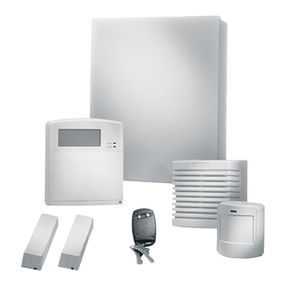
How to order
AS399 Siren-beige
AB450 Beacon-white
AB451 Beacon-amber
AB452 Beacon-blue
AB453 Beacon-red
- 1 -
AS399
AS399 Outdoor Siren
and AB450 Series Beacons
Installations Manual
ADJUST TAMPERSWITCH SPRING
CLOSE YOUR PROTECTION COVER
CLOSE YOUR
SIREN
PLASTIC WASHER
LOCATES BEHIND COVER
FLASH - +
+
-
BATTERY
-+
-+
-
+
-+
12345678910
RED
BLACK
SIREN HOLD-OFF VOLTAGE (**)
BEACON HOLD-OFF VOLTAGE (**)
INPUT POWER (13.0 - 14.2 V )
TAMPER LOOP
TAMPER
SWITCH
SPEAKER
3
LOR
J2 J1
CUT-OFF
TIMER
J4 J5 J6 J7
HOLD OFF
PROGRAMMING
- 2 -
**) Siren and flashlight can be held-off by a positive or negative voltage,
unless otherwise selected by cutting J4-J7.
**) La sirène et le flash peuvent être déclenchés avec une tension
positive ou négative, sauf en sac de programmation selective en
coupant le pontage J4-J7.
**) Sirene en flitslicht kunnen worden gestart door verwijderen van een
positief of negatief houdspanning. Programmering wordt gedaan door
middel van draadbruggen J4-J7.
**) Die Sirene und Blitzlampe kann wahlweise mit einer positiven oder
negativen Haltespannung angesteurert werden. Die programmierung
erfogt über die Brücken J4-J7.
**) La sirena ed il lampeggiante possono essere controllati sia da un
positivo che da un negativo. Il comando può anche essere programmato
selettivamento agendo sui cavallotti J4-J7.
**) La sirena y el flash pueden ser activados por una tensión positiva o
negativa. A menos que se seleccione contando los puentes J4-J7.
Especificaciones
técnicas:
Alimentación
Corriente auxiliar
Corriente de
funcionamiento
Nivel sonoro
Frecuencia
Temporizador
Temperatura de
funcionamiento
Peso
Dimensiones
Batería recomendada
Flash:
Alimentación
Corriente de
funcionamiento
Nivel luminoso
Duración
Proporciòn
de destellos
Temperatura de
funcionamiento
Red de supresión de
daños por radiación
3'
5'
10'
20'
J1
Standard ex factory setting
J2 J4 J5 J6 J7
✂
✂✂✂ ✂✂✂✂
Hold-off
programming
+Hold / - Hold
+ Hold
-Hold
Timer
programming. Siren Beacon
Programmation
de la polarité de blocage
+Blocage / - Blocage
+ Blocage
-Blocage
3'
5'
10'
20'
J1
Réglage usine
J2 J4 J5 J6 J7
✂
✂✂✂ ✂✂✂✂
Programmation
de la minuterie Sirène Flash
Programmering
van het flitslicht en sirene sturing
Programmering
van de timer.
+Hold / - Hold
+ Hold
-Hold
3'
5'
10'
20'
J1
Standaardinstelling in fabriek
J2 J4 J5 J6 J7
✂
✂✂✂ ✂✂✂✂
Sirene Flitslicht
Timer
Programmierung. Haltespannung
Programmierung
+Halte / - Halte
+ Halte
-Halte
3'
5'
10'
20'
J1
Werkseitige Einstellung
J2 J4 J5 J6 J7
✂
✂✂✂ ✂✂✂✂
Sirene
Blitzlampe
Programmazione
del timer
+C / - C
+ C
-C
omandi omandi
omandi
omandi
3'
5'
10'
20'
J1
Settaggio standard di fabbrica
J2 J4 J5 J6 J7
✂
✂✂✂ ✂✂✂✂
Sirena
Faro
Programmazione
dei comandi
Programación del
temporizador Programación de
activación
+Desparo / - Desparo
+ Desparo
-Desparo
3'
5'
10'
20'
J1
Valor estándar de fábrica
J2 J4 J5 J6 J7
✂
✂✂✂ ✂✂✂✂
Sirena
Flash
- 3 -
Technical
data:
Supply
Standby Current
Operating Current
Sound Output
Frequency
Cut off timer
Working temperature
Weight
Dimensions
Recommended battery
Beacon:
Supply
Operating current
Light output
Life time
Flash rate
Working temperature
Spike suppression
Caractéristiques
technique:
Alimentation
Consommation
permanente
Consommation
en alarme
Niveau sonore
Fréquence
Temporisation de sirène
Température de
fonctionnement
Poids
Dimensions
Batterie recommandée
Flash:
Alimentation
Consommation
en alarme
Flux lumineux
Longévité
Vitesse
de clignotement
Température de
fonctionnement
Réseau antiparasites
Caratteristiche
tecniche:
Alimentazione
Corrente in standby
Corrente in
funzionamento
Uscita sonora
Frequenza
Timer d’esclusion
Temperatura di
funzionamento
Peso
Dimensioni
Batterie consigliate
Faro:
Alimentazione
Corrente in
funzionamento
Uscita luminosa
Durata
Cadenza di
lampeggiamento
Temperatura di
funzionamento
Rete a soppressione
di punta
13.0 V - 14.2 V
25 mA (closed line)
0.6 A
94 dB at 1 m; -
85 dB at 3 m
1.8 - 2.8 kHz
Preset at 3'
Adjustable 5', 10', 20'
-25 °C to +70 °C
(without battery)
0 °C to 40 °C (with batt.)
3 kg
260 x 275 x 87 mm
12 V - 3 Ah min.
13.8 V
110 mA
100.000 peak lumens
1.000.000 flashes
60/minute
-25 °C to +70 °C
Standard fitted
Technische
Daten:
Versorgungsspannung
Stromaufnahme
in Ruhe
Stromaufnahme in
Betrieb
Schalldruck
Frequenz
Alarmierungsdauer
Betriebstemperatur
Gewicht
Abmessungen
Emphohlene Batterie
Blitzlampe:
Versorgungsspannung
Stromaufnahme
in Betrieb
Lichtpegel
Lebensdauer
Blitzfrequenz
Betriebstemperatur
Entstörnetzwerk
Technische
gegevens:
Voeding
Ruststroom
Bedrijfsstroom
Geluidssterkte
Frequentie
Tijdinstelling
Bedrijfstemperatuur
Gewicht
Afmetingen
Aanbevolen accu
Flitslicht:
Voedingsspanning
Bedrijfsstroom
Lichtsterkte
Levensduur
Knippersnelheid
Bedrijfstemperatuur
Ontstoringsnetwerk
Procédure de raccordement.
Raccorder d'abord la sirène comme indiqué, à la centrale (alimentations coupées), avant de
connecter la batterie. La sirène sera activée si la tension d'alimentation est supprimée ou chute de
manière significative, ou bien si la tension de blocage est supprimée.
La temporisation de la sirène est contrôlée par J1 et J2.
.
Aansluitprocedure
Sluit, voordat de accu aangesloten wordt, eerst het controlepaneel aan (spanning uitgeschakeld)
zoals hierboven staat aangegeven. De sirene wordt geaktiveerd wanneer de voedingsspanning
verwijderd of aanzienlijk verlaagd wordt of als de hold-off spanning verwijderd wordt.
De sirenetijd kan ingesteld worden met J1 en J2.
Procedura di cablaggio
Prima di alimentare le apparecchiature, collegate la sirene alla centrale sequendo lo schema
mostrato sopra. La sirena viene attivata se viene rimossa l'alimentazione o la stessa cala in modo
significativo oppure se viene rimosso il riferimento di comando.
La temporizzazione interna della sirena viene impostata dai cavallotti J1 e J2.
Procedimiento de cableado
Eu primer lugar, cablear la unidad de control (siu alimentación) a la sirena, como se muestra a
continuación, antes de conectar la batería. Si disparará la sirena par falta de alimentación o
disminuya significativamente o se varia la tension de disparo.
El tiempo de activación de sirena se controla mediante J1 y J2.
Anschaltung des Signalgebers
Zunächst die oben abgebildete Anschaltung an die Zentrale (im spannungsloseb Zustand) durchführen
bevor der Akku an die Sirene angeschlossen wird. Die Sirene wird aktiviert, indem die
Versorgungsspannung unterbrochen wird oder signifkant abfällt oder sobalt die Sirenenhaltespannung
unterbrochen wird.
Die Sirenenaktivierungsdauer wird durch J1 und J2 festgelegt.
Wiring procedure
First, wire the control panel (power down) to the siren as shown above, before connecting the battery.
When the battery is connected for the first time, the siren will give a short beep. The siren will be
activated if the input power is removed or drops significantly or if the siren hold-off voltage is removed.
Siren cut-off time is controlled by J1 and J2.

Connection examples
1234 67 8910
INT. bell
EXT. bell
CD Series
5
4K7
TAMPER
SPEAKER
- +
BEACON
- +
POWER
SIREN
HOLD
OFF
BEACON
HOLD
OFF
NOTE:
Bell outputs are programmed
for inverted operation.
-V
+V
-
+
-
+
1234 678910
INT. bell
CD Series
5
4K7
TAMPER SIREN
HOLD
OFF
BEACON
HOLD
OFF
- +
BEACON
SPEAKER
EXT. bell
- +
POWER
INT.
SIRENE
-
+
Output
NOTE:
Typically with int. bell
2228-4B© 2003. GE Interlogix B.V.. All rights reserved.
NOTE: Cut jumpers J5 & J7 for negative hold-off
AS Series
NOTE: Cut jumpers J5 & J7 for negative hold-off
AS Series
-V
+V
-
+
-
+
- 4 -
12345678910
1K
1K
INT bell
-Ve apply
to strobe
EXT bell
-Ve apply
to ring
- Ve supply
-Ve
tamper return
+Ve supply
SPEAKER TAMPER
Typical
wiring
for UK
& Irish
panels
- +
BEACON
- +
POWER
SIREN
HOLD
OFF
BEACON
HOLD
OFF
AS Series
1234 67 89105
SPEAKER
- +
BEACON
NC NC
POWER
- +
TAMPER
NOTE: For use without a battery cut J3
AS Series


Accredited by the
Dutch Consul for
Certification
ISO 9001
To be connected to an external current limited power supply. (Advised: 5 Amp.) IP35

This manual suits for next models

4

Other GE Security System manuals

GE GEC-4VDPC Assembly instructions

GE

GE GEC-4VDPC Assembly instructions

GE 8RP Board Assembly instructions

GE

GE 8RP Board Assembly instructions

GE CareGard User manual

GE

GE CareGard User manual

GE 60-806-95R-16Z - Security Concord Express System Control... User manual

GE

GE 60-806-95R-16Z - Security Concord Express System Control... User manual

GE Concord User manual

GE

GE Concord User manual

GE SIMON XT User manual

GE

GE SIMON XT User manual

GE NX-10 User manual

GE

GE NX-10 User manual

GE Euro Simon User manual

GE

GE Euro Simon User manual

GE Security Pro 7000 User manual

GE

GE Security Pro 7000 User manual

GE 45235 User manual

GE

GE 45235 User manual

GE Concord express User manual

GE

GE Concord express User manual

GE Advent User manual

GE

GE Advent User manual

GE Telligence Patient-Staff Communications... User manual

GE

GE Telligence Patient-Staff Communications... User manual

GE 56789 User manual

GE

GE 56789 User manual

GE NX-108E - Security NetworX NX-4 System User manual

GE

GE NX-108E - Security NetworX NX-4 System User manual

GE SIMON XT User manual

GE

GE SIMON XT User manual

GE Supra KeySafe User manual

GE

GE Supra KeySafe User manual

GE Interlogix 60-875 Simon User manual

GE

GE Interlogix 60-875 Simon User manual

GE Wireless Color Digital Home Monitoring Kit User manual

GE

GE Wireless Color Digital Home Monitoring Kit User manual

GE ActiveKEY User manual

GE

GE ActiveKEY User manual

GE 45131 User manual

GE

GE 45131 User manual

GE 610 User manual

GE

GE 610 User manual

GE SIMON XT Instruction manual

GE

GE SIMON XT Instruction manual

GE 600-1064-95R b User manual

GE

GE 600-1064-95R b User manual

Popular Security System manuals by other brands

ADT Entrepreneur 3000EN Programming guide

ADT

ADT Entrepreneur 3000EN Programming guide

Genie Lift Guard GS-30 Operator's manual supplement

Genie

Genie Lift Guard GS-30 Operator's manual supplement

SiKom A-Comfort quick start guide

SiKom

SiKom A-Comfort quick start guide

Risco lightsys 2 user manual

Risco

Risco lightsys 2 user manual

Spectra H100TF manual

Spectra

Spectra H100TF manual

First Alert D-575 Specifications

First Alert

First Alert D-575 Specifications

Honeywell Ademco VISTA-20P user guide

Honeywell

Honeywell Ademco VISTA-20P user guide

Argus Security Taurus TW-CP-R-01 manual

Argus Security

Argus Security Taurus TW-CP-R-01 manual

Busch-Jaeger Busch-Infoline  1564 U-1 Series installation instructions

Busch-Jaeger

Busch-Jaeger Busch-Infoline 1564 U-1 Series installation instructions

SmartCell SC-51-0100-0001-99 installation guide

SmartCell

SmartCell SC-51-0100-0001-99 installation guide

Whelen Engineering Company GTT 795DM installation manual

Whelen Engineering Company

Whelen Engineering Company GTT 795DM installation manual

Rogers Door Sensor Setup guide

Rogers

Rogers Door Sensor Setup guide

heddier electronic Human Detector Flex instruction manual

heddier electronic

heddier electronic Human Detector Flex instruction manual

Scotty eyesite550 user manual

Scotty

Scotty eyesite550 user manual

HOME8 C12014 quick start guide

HOME8

HOME8 C12014 quick start guide

Luda Elektronik horseAlarm manual

Luda Elektronik

Luda Elektronik horseAlarm manual

ADT K5309V2 user guide

ADT

ADT K5309V2 user guide

eTIGER ES-D3B user manual

eTIGER

eTIGER ES-D3B user manual

manuals.online logo
manuals.online logoBrands
  • About & Mission
  • Contact us
  • Privacy Policy
  • Terms and Conditions

Copyright 2025 Manuals.Online. All Rights Reserved.