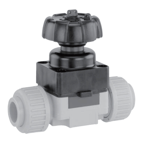
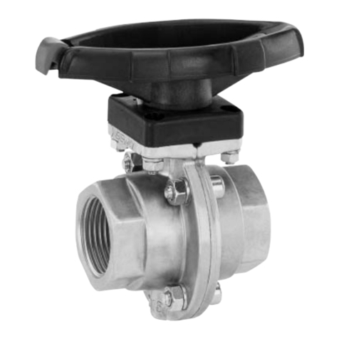
GEM 717 User manual

GEMÜ 717
Manually operated ball valve
Operating instructions
EN
further information
webcode: GW-717

All rights including copyrights or industrial property rights are expressly reserved.
Keep the document for future reference.
© GEMÜ Gebr. Müller Apparatebau GmbH & Co. KG
01.10.2019
www.gemu-group.com2 / 40GEMÜ 717

Contents
1 General information ................................................... 4
1.1 Information ......................................................... 4
1.2 Symbols used ..................................................... 4
1.3 Definition of terms ............................................. 4
1.4 Warning notes .................................................... 4
2 Safety information .................................................... 4
3 Product description ................................................... 5
4 Correct use ................................................................ 7
5 Order data ................................................................. 8
6 Technical data ........................................................... 10
7 Dimensions ............................................................... 13
8 Manufacturer's information ....................................... 23
8.1 Delivery ............................................................... 23
8.2 Packaging ........................................................... 23
8.3 Transport ............................................................ 23
8.4 Storage ............................................................... 23
9 Installation in piping .................................................. 23
9.1 Preparing for installation ................................... 23
9.2 Installation with inserts for solvent cementing 24
9.3 Installation with inserts for welding .................. 25
9.4 Installation with screw-type inserts ................. 25
9.5 Installation with flanged connection ................. 26
10 Electrical connection of electrical position indicators
(optional accessories) ............................................... 26
11 Commissioning ......................................................... 27
12 Operation .................................................................. 27
13 Error clearance .......................................................... 30
14 Inspection and servicing ............................................ 31
15 Removal from piping ................................................. 36
16 Returns ..................................................................... 36
17 EU Declaration of conformity 2-way ball valve ........... 37
18 EU Declaration of conformity 3-way ball valve ........... 38
GEMÜ 717www.gemu-group.com 3 / 40

www.gemu-group.com4 / 40GEMÜ 717
1 General information
1.1 Information
– The descriptions and instructions apply to the stand-
ard versions. For special versions not described in this
document the basic information contained herein ap-
plies in combination with any additional special docu-
mentation.
– Correct installation, operation, maintenance and repair
work ensure faultless operation of the product.
– Should there be any doubts or misunderstandings, the
German version is the authoritative document.
– Contact us at the address on the last page for staff
training information.
1.2 Symbols used
The following symbols are used in this document:
Symbol Meaning
Tasks to be performed
Response(s) to tasks
– Lists
1.3 Definition of terms
Working medium
The medium that flows through the GEMÜ product.
1.4 Warning notes
Wherever possible, warning notes are organised according to
the following scheme:
SIGNAL WORD
Type and source of the danger
Possible
symbol for
the specific
danger
Possible consequences of non-observance.
Measures for avoiding danger.
Warning notes are always marked with a signal word and
sometimes also with a symbol for the specific danger.
The following signal words and danger levels are used:
DANGER
Imminent danger!
▶Non-observance can cause death or
severe injury.
WARNING
Potentially dangerous situation!
▶Non-observance can cause death or
severe injury.
CAUTION
Potentially dangerous situation!
▶Non-observance can cause moderate
to light injury.
NOTICE
Potentially dangerous situation!
▶Non-observance can cause damage to
property.
The following symbols for the specific dangers can be used
within a warning note:
Symbol Meaning
Danger of explosion
Corrosive chemicals
Hot plant components!
2 Safety information
The safety information in this document refers only to an in-
dividual product. Potentially dangerous conditions can arise
in combination with other plant components, which need to
be considered on the basis of a risk analysis. The operator is
responsible for the production of the risk analysis and for
compliance with the resulting precautionary measures and
regional safety regulations.
The document contains fundamental safety information that
must be observed during commissioning, operation and
maintenance. Non-compliance with these instructions may
cause:
– Personal hazard due to electrical, mechanical and
chemical effects.
– Hazard to nearby equipment.
– Failure of important functions.
– Hazard to the environment due to the leakage of dan-
gerous materials.
The safety information does not take into account:
– Unexpected incidents and events, which may occur
during installation, operation and maintenance.
– Local safety regulations which must be adhered to by
the operator and by any additional installation person-
nel.

www.gemu-group.com 5 / 40 GEMÜ 717
Prior to commissioning:
1. Transport and store the product correctly.
2. Do not paint the bolts and plastic parts of the product.
3. Carry out installation and commissioning using trained
personnel.
4. Provide adequate training for installation and operating
personnel.
5. Ensure that the contents of the document have been fully
understood by the responsible personnel.
6. Define the areas of responsibility.
7. Observe the safety data sheets.
8. Observe the safety regulations for the media used.
During operation:
9. Keep this document available at the place of use.
10. Observe the safety information.
11. Operate the product in accordance with this document.
12. Operate the product in accordance with the specifica-
tions.
13. Maintain the product correctly.
14. Do not carry out any maintenance work and repairs not
described in this document without consulting the manu-
facturer first.
In cases of uncertainty:
15. Consult the nearest GEMÜ sales office.
3 Product description
3.1 Construction
3
1
4
2
Item Name Materials
1 Ball valve body PVC-U, PVC-C, ABS, PP-H or PVDF
2 Pipe
connections
PVC-U, PVC-C, ABS, PP-H or PVDF
3 Anti-twist
protection
POM
4 Hand lever HIPVC
Ball valve seals FPM, EPDM, FFKM
Ball valve seat
seals
PTFE
3.2 Description
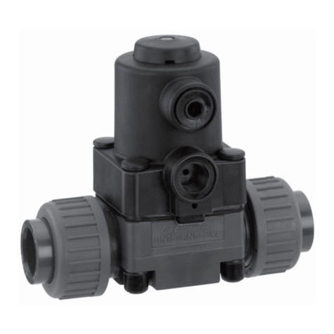
The GEMÜ 717 2/2 or 3/2-way plastic ball valve has an ergo-
nomically designed hand lever and is manually operated. The
seat seal is made of PTFE.
3.3 Function
The product is a 2/2 or 3/2-way plastic ball valve equipped
with a plastic manual operator. The threaded connection
locking device enables the unions to be locked in place.
The valve body and the seal material are available in various
designs as shown in the datasheet. Optional accessories are
available on request (see chapter "Accessories").
3 Product description

www.gemu-group.com6 / 40GEMÜ 717
3 Product description
3.4 Port positions
3.4.1 T-port
CLOSED end
position
OPEN end po-
sition
Condition as
supplied to
customer
OPEN
Delivery condition
Code T
12
3
1 2
3
1 2
3
Optional port positions, can be user adjusted
Code 2
12
3
12
3
12
3
Code 3
12
3
12
3
12
3
Code 4
1 2
3
12
3
12
3
3.4.2 L-port
CLOSED end
position
OPEN end po-
sition
Condition as
supplied to
customer
OPEN
Delivery condition
Code L
12
3
12
3
12
3
Optional port positions, can be user adjusted
Code 6
2
3
1
12
3
12
3
3.4.3 Control ball
View with a scale Control ball
Code R
View with a scale Control ball
For 0°- 90° control range, linear control characteristic
between port position and percentage flow rate.
For ball configuration (R), an indicator plate is fitted on the
ball valve body.
NOTE: Ball configuration (R) cannot be retrofitted to
standard 2/2-way bodies at a later date.

www.gemu-group.com 7 / 40 GEMÜ 717
4 Correct use
DANGER
Danger of explosion
▶Risk of death or severe injury.
●Do not use the product in potentially
explosive zones.
WARNING
Improper use of the product!
▶Risk of severe injury or death.
▶Manufacturer liability and guarantee will be void.
●Only use the product in accordance with the operating
conditions specified in the contract documentation and
this document.
The product is designed for installation in piping systems
and for controlling a working medium.
The product is not intended for use in potentially explosive
areas.
The product is controlled via a manual operator.
●Use the product in accordance with the technical data.
4 Correct use

5 Order data
The order data provide an overview of standard configurations.
Please check the availability before ordering. Other configurations available on request.
Order codes
1 Type Code
Kunststoff-Kugelhahn,
manuell betätigt
717
2 DN Code
DN 10 10
DN 15 15
DN 20 20
DN 25 25
DN 32 32
DN 40 40
DN 50 50
DN 65 65
DN 80 80
DN 100 100
3 Body configuration Code
2/2-way body D
Mehrwege-Ausführung M
4 Connection type Code
Klebe- beziehungsweise Schweißmuffe DIN 2
Armaturenverschraubung mit Einlegeteil Zoll - BS
(Muffe)
33
Flansch ANSI Class 125/150 RF 39
Armaturenverschraubung mit Einlegeteil JIS
(Muffe)
3T
Flansch EN 1092, PN 10, Form B,
Baulänge FTF EN 558 Reihe 1, ISO 5752, basic
series 1
4
Armaturenverschraubung mit Einlegeteil DIN (IR-
Stumpfschweißen)
78
Armaturenverschraubung mit Einlegeteil
Gewindemuffe Rp
7R
Threaded socket NPT 31
5 Ball valve material Code
PVC-U, grau 1
PVC-C, chloriertes Polyvinylchlorid 2
PVDF 20
ABS 4
PP-H, grau 5
6 Seal material Code
FPM, maximal -15°C - +210°C 4
EPDM, maximal -20°C - +95°C 14
FFKM F5
7 Control function Code
manuell betätigt 0
8 Ball configur./port position Code
L-Kugel, Standard Endlage "Auf", Anschluss 2 und
3 offen,
L-Kugel, Standard Endlage "Zu", Anschluss 1 und
3 offen
L
T-Kugel, Standard Endlage "Auf", Anschluss 1, 2
und 3 offen,
T-Kugel, Standard Endlage "Zu", Anschluss 1 und
3 offen
T
T-Kugel, Endlage "Auf", Anschluss 1 und 3 offen,
T-Kugel, Endlage "Zu", Anschluss 1 und 2 offen
2
T-Kugel, Endlage "Auf", Anschluss 1 und 2 offen,
T-Kugel, Endlage "Zu", Anschluss 2 und 3 offen
3
T-Kugel, Endlage "Auf", Anschluss 2 und 3 offen,
T-Kugel, Endlage "Zu", Anschluss 1, 2 und 3 offen
4
L-Kugel, Endlage "Auf", Anschluss 1 und 3 offen,
L-Kugel, Endlage "Zu", Anschluss 1 offen
6
R-Kugel (Regelkugel)
für Regelbereich 0° - 90°
Lineare Kennlinie zwischen Kugelstellung und
prozentualem Durchfluss
R
9 Type of design Code
Without
Einlegeteil aus PE 1187
10 CONEXO Code
without
Integrated RFID chip for electronic identification
and traceability
C
5 Order data
www.gemu-group.com
8 / 40
GEMÜ 717

Order example
Order option Code Description
1 Type 717 Kunststoff-Kugelhahn,
manuell betätigt
2 DN 15 DN 15
3 Body configuration M Mehrwege-Ausführung
4 Connection type 2 Klebe- beziehungsweise Schweißmuffe DIN
5 Ball valve material 1 PVC-U, grau
6 Seal material 14 EPDM, maximal -20°C - +95°C
7 Control function 0 manuell betätigt
8 Ball configur./port position L L-Kugel, Standard Endlage "Auf", Anschluss 2 und 3 offen,
L-Kugel, Standard Endlage "Zu", Anschluss 1 und 3 offen
9 Type of design Without
10 CONEXO without
5 Order data
www.gemu-group.com 9 / 40 GEMÜ 717

6 Technical data
6.1 Medium
Working medium: Corrosive, inert, gaseous and liquid media and steam which have no negative impact on the phys-
ical and chemical properties of the body and seal material.
6.2 Temperature
Media temperature: see Pressure / temperature diagram
Seal material: FPM: -15 – 210 °C
EPDM: -20 – 95 °C
Ambient temperature: Valve body ABS: -10 to 50 °C
Valve body PP-H: 5 to 60 °C
Valve body PVC-U, PVC-C: 10 to 50 °C
Valve body PVDF: -5 to 50 °C
6.3 Pressure
Operating pressure: Pressure / temperature diagram
0
2
4
6
8
10
12
14
16
-40 -20 020 40 60 80 100 120 140
PVDF
PVC-C
PVC-U
PP-H
ABS
Operating pressure [bar]
Temperature [°C]
Data for extended temperature ranges on request. Please note that the ambient temperature and media tem-
perature generate a combined temperature at the valve body which must not exceed the above values.
Kv values: DN Body configuration
2/2-way Multi-port (code M)
(code D) (code R) T-port T-port T-port T-port L-port
12
3
1 2
3
12
3
12
3
12
3
10 4.8 4.98 2.2 1.5 2.4 4.7 2.9
15 12.0 5.28 3.3 2.1 3.9 11.7 4.4
20 23.1 8.10 8.1 5.7 8.7 22.8 9.0
25 46.2 15.36 12.3 8.4 14.7 45.6 15.9
32 66.0 28.68 23.4 16.2 27.6 63.0 28.5
40 105.0 35.52 28.5 19.8 36.0 102.0 37.2
50 204.0 64.08 54.0 37.2 72.0 192.0 73.2
65 315.0 - - - - - -
80 426.0 - - - - - -
100 570.0 - - - - - -
Kv values in m³/h
Control diagram: with control ball (code R)
www.gemu-group.com
10 / 40
GEMÜ 717
6 Technical data

Control diagram:
0 10 20 30 40 50 60 70 80 90 100
40
50
60
70
80
90
100
0
10
20
30
Opening [%]
KV100 value [%]
For 0°- 90° control range, linear control characteristic between port position and percentage flow
rate.
NOTE: Ball configuration (R) cannot be retrofitted to standard 2/2-way bodies at a later date.
6.4 Mechanical data
Weight: Ball valve
DN Body configuration
2/2-way (code D) Multi-port (code M)
Material code 1)
1, 2 4 5 20 1, 2, 4 5 20
10 215 160 150 291 - - -
15 205 160 145 272 310 207 390
20 330 265 218 445 550 353 669
25 438 345 298 584 790 498 952
32 693 550 480 938 1275 895 1501
40 925 730 682 1242 1660 1022 1959
50 1577 1280 1166 2187 2800 1945 3324
65 4380 4380 3090 4350 - - -
80 7200 7200 5080 7200 - - -
100 11141 11141 7725 11141 - - -
Weight in g
1) Ball valve material
Code 1: PVC-U, grau
Code 2: PVC-C, chloriertes Polyvinylchlorid
Code 4: ABS
Code 5: PP-H, grau
Code 20: PVDF
Hand lever
DN 10 DN 15 DN 20 DN 25 DN 32 DN 40 DN 50 DN 65 DN 80 DN 100
18 18 32 31 60 40 106 350 600 690
Weight in g
GEMÜ 717www.gemu-group.com 11 / 40
6 Technical data

Torques: DN 2/2-way code D Multi-port code M
PN 6 PN 10 PN 16 PN 10 PN 16
Material code 1)
1, 2, 4, 5,
20
5 1, 2, 20 4 1, 2 5 1, 2
10 - 2.4 3.6 3 - - -
15 - 2.4 3.6 3 2.4 2.4 3.6
20 - 3.6 4 4 3.6 3.6 4.8
25 - 4.8 6 6 5 5 5.4
32 - 7.2 7.2 7.2 7.2 7.2 11.5
40 - 8.6 10 10 9.6 10 14.8
50 - 12.4 16 16 14.8 14.8 23.3
65 20 25 30 30 - - -
80 25 35 45 45 - - -
100 40 55 65 65 - - -
Torques in Nm
1) Ball valve material
Code 1: PVC-U, grau
Code 2: PVC-C, chloriertes Polyvinylchlorid
Code 4: ABS
Code 5: PP-H, grau
Code 20: PVDF
www.gemu-group.com
12 / 40
GEMÜ 717
6 Technical data

7 Dimensions
7.1 2/2-way body
7.1.1 Valve body material PVC-U (code 1), body configuration D
H
ØD
LA
LB
LC
ød
A
A
LA
LC
øf
A
H
ØF
LC
DN 10 - 50
E
DN 10 - 50
ød
A
H
Connection type
code 2, 33, 3M, 3T, 7R
Handhebel DN 65 - 100
Connection type
code 2 (PVDF), 78, 78*
Connection type
code 4, 39
Hand lever DN 65 - 100
DN Connection type code 1) 4 39 78* 4 39 4 39 78*
d ød ØD A H LA LC øf ØF E
15 1/2“ 20 54 40 54 65 130 143 175 14 15.9 65 60.3 55
20 3/4“ 25 65 49 65 70 150 172 210 14 15.9 75 69.9 70
25 1“ 32 73 49 69.5 78 160 187 226 14 15.9 85 79.4 74
32 1 ¼“ 40 86 64 82.5 88 180 190 243 18 15.9 100 88.9 78
40 1 ½“ 50 98 64 89 93 200 212 261 18 15.9 110 98.4 84
50 2“ 63 122 76 108 111 230 234 293 18 19.1 125 120.7 91
65 2 ½“ 75 164 175 164 133 290 290 356 17 18 145 139.7 111
80 3“ 90 203 272 177 149 310 310 390 17 18 160 152.4 118
100 4“ 110 238 330 195 167 350 350 431 17 18 180 190.5 132
Dimensions in mm
* Inserts according to valve body material,
special version: PE insert, design code 1187
1) Connection type
Code 4: Flansch EN 1092, PN 10, Form B, Baulänge FTF EN 558 Reihe 1, ISO 5752, basic series 1
Code 39: Flansch ANSI Class 125/150 RF
Code 78: Armaturenverschraubung mit Einlegeteil DIN (IR-Stumpfschweißen)
GEMÜ 717www.gemu-group.com 13 / 40
7 Dimensions

7.1.2 Valve body material PVC-U (code 1), body configuration D
H
ØD
LA
LB
LC
ød
A
A
LA
LC
øf
A
H
ØF
LC
DN 10 - 50
E
DN 10 - 50
ød
A
H
Connection type
code 2, 33, 3M, 3T, 7R
Handhebel DN 65 - 100
Connection type
code 2 (PVDF), 78, 78*
Connection type
code 4, 39
Hand lever DN 65 - 100
DN Connection type code 1) 2 33 3M 3T 7R 2 33 3M 3T 7R
d ød ØD A LA H LB LC
10 3/8“ 16 54 40 65 54 75 74 - - - 103 103 - - -
15 1/2“ 20 54 40 65 54 71 70 72 71 80 103 103 117 131 110
20 3/4“ 25 65 49 70 65 77 77 78 77 83.5 115 115 129 147 116
25 1“ 32 73 49 78 69.5 84 83 84.6 84 96 128 128 142 164 134
32 1 ¼“ 40 86 64 88 82.5 94 94 98 94 110 146 146 162 182 153
40 1 ½“ 50 98 64 93 89 102 104 102 102 113 164 164 172 212 156
50 2“ 63 122 76 111 108 123 127 122.6 122 134.5 199 199 199 248 186
65 2 ½“ 75 164 175 133 164 147 147 146 145 174.5 235 235 235 267 235
80 3“ 90 203 272 149 177 168 168 174 165 203.5 270 270 270 294 270
100 4“ 110 238 330 167 195 186 182 193 202 229.5 308 308 308 370 308
Dimensions in mm
1) Connection type
Code 2: Klebe- beziehungsweise Schweißmuffe DIN
Code 33: Armaturenverschraubung mit Einlegeteil Zoll - BS (Muffe)
Code 3M: Union end with inch insert - ASTM (socket)
Code 3T: Armaturenverschraubung mit Einlegeteil JIS (Muffe)
Code 7R: Armaturenverschraubung mit Einlegeteil Gewindemuffe Rp
www.gemu-group.com
14 / 40
GEMÜ 717
7 Dimensions

7.1.3 Valve body material PVC-C (code 2), body configuration D
H
ØD
LA
LB
LC
ød
A
A
LA
LC
øf
A
H
ØF
LC
DN 10 - 50
E
DN 10 - 50
ød
A
H
Connection type
code 2, 33, 3M, 3T, 7R
Handhebel DN 65 - 100
Connection type
code 2 (PVDF), 78, 78*
Connection type
code 4, 39
Hand lever DN 65 - 100
DN Connection type code 1) 2 3M 2 4 39 3M 4 39 4 39
d ød øD A H LA LB LC øf ØF
10 3/8“ 16 54 40 54 65 75 - 103 - - - - - - -
15 1/2“ 20 54 40 54 65 71 72 103 130 143 117 14 15.9 65 60.3
20 3/4“ 25 65 49 65 70 77 78 115 150 172 129 14 15.9 75 69.9
25 1“ 32 73 49 69.5 78 84 84.6 128 160 187 142 14 15.9 85 79.4
32 1 ¼“ 40 86 64 82.5 88 94 98 146 180 190 162 18 15.9 100 88.9
40 1 ½“ 50 98 64 89 93 102 102 164 200 212 172 18 15.9 110 98.4
50 2“ 63 122 76 108 111 123 122.6 199 230 234 199 18 19.1 125 120.7
65 2 ½“ 75 164 175 164 133 147 146 235 290 290 235 17 18 145 139.7
80 3“ 90 203 272 177 149 168 174 270 310 310 270 17 18 160 152.4
100 4“ 110 238 330 195 167 186 193 308 350 350 308 17 18 180 190.5
Dimensions in mm
1) Connection type
Code 2: Klebe- beziehungsweise Schweißmuffe DIN
Code 4: Flansch EN 1092, PN 10, Form B, Baulänge FTF EN 558 Reihe 1, ISO 5752, basic series 1
Code 39: Flansch ANSI Class 125/150 RF
Code 3M: Union end with inch insert - ASTM (socket)
GEMÜ 717www.gemu-group.com 15 / 40
7 Dimensions

7.1.4 Valve body material ABS (code 4), body configuration D
H
ØD
LA
LB
LC
ød
A
A
LA
LC
øf
A
H
ØF
LC
DN 10 - 50
E
DN 10 - 50
ød
A
H
Connection type
code 2, 33, 3M, 3T, 7R
Handhebel DN 65 - 100
Connection type
code 2 (PVDF), 78, 78*
Connection type
code 4, 39
Hand lever DN 65 - 100
DN Connection type code 1) 2 7R 33 2, 33 7R
d ød øD A LA H LB LC
10 3/8" 15 55 40 65 49 75 - 75 103 -
15 1/2“ 20 55 40 65 49 71 80 71 103 110
20 3/4“ 25 66 49 70 59 77 83.4 77 115 116
25 1“ 32 75 49 78 66 84 95.8 84 128 134
32 1 ¼“ 40 87 64 88 75 94 110.2 94 146 153
40 1 ½“ 50 100 64 93 87 102 113.2 102 164 156
50 2“ 63 122 76 111 101 123 134.6 123 199 186
65 2 ½“ 75 164 175 133 164 147 - 147 235 -
80 3“ 90 203 272 149 177 168 - 168 270 -
100 4“ 110 238 330 167 195 186 - 186 308 -
Dimensions in mm
1) Connection type
Code 2: Klebe- beziehungsweise Schweißmuffe DIN
Code 33: Armaturenverschraubung mit Einlegeteil Zoll - BS (Muffe)
Code 7R: Armaturenverschraubung mit Einlegeteil Gewindemuffe Rp
www.gemu-group.com
16 / 40
GEMÜ 717
7 Dimensions

7.1.5 Valve body material PP-H (code 5), body configuration D
H
ØD
LA
LB
LC
ød
A
A
LA
LC
øf
A
H
ØF
LC
DN 10 - 50
E
DN 10 - 50
ød
A
H
Connection type
code 2, 33, 3M, 3T, 7R
Handhebel DN 65 - 100
Connection type
code 2 (PVDF), 78, 78*
Connection type
code 4, 39
Hand lever DN 65 - 100
DN Connection type code 1) 2 7R 2 4 39 78/78* 7R 78/78* 4 39 4 39
d ød øD A H LA LB LC E øf ØF
10 3/8“ 16 54 40 - 65 75 - 102 - - - - - - - - -
15 1/2“ 20 54 40 54 65 73 80 102 130 143 175 110 55 14 15.9 65 60.3
20 3/4“ 25 65 49 65 70 82 83 114 150 172 210 116 70 14 15.9 75 69.9
25 1“ 32 73 49 69.5 78 90 96 126 160 187 226 134 77 14 15.9 85 79.4
32 1 ¼“ 40 86 64 82.5 88 100 110 141 180 190 243 153 78 18 15.9 100 88.9
40 1 ½“ 50 98 64 89 93 117 113 164 200 212 261 156 84 18 15.9 110 98.4
50 2“ 63 122 76 108 111 144 134 199 230 234 293 186 91 18 15.9 125 120.7
65 2 ½“ 75 164 175 164 133 153 - 213 290 290 356 - 111 17 18 145 139.7
80 3“ 90 203 272 177 149 173 - 239 310 310 390 - 118 17 18 160 152.4
100 4“ 110 238 330 195 167 199 - 268 350 350 431 - 132 17 18 180 190.5
Dimensions in mm
* Inserts according to valve body material,
special version: PE insert, design code 1187
1) Connection type
Code 2: Klebe- beziehungsweise Schweißmuffe DIN
Code 4: Flansch EN 1092, PN 10, Form B, Baulänge FTF EN 558 Reihe 1, ISO 5752, basic series 1
Code 39: Flansch ANSI Class 125/150 RF
Code 78: Armaturenverschraubung mit Einlegeteil DIN (IR-Stumpfschweißen)
Code 7R: Armaturenverschraubung mit Einlegeteil Gewindemuffe Rp
GEMÜ 717www.gemu-group.com 17 / 40
7 Dimensions

7.1.6 Valve body material PVDF (code 20), body configuration D
H
ØD
LA
LB
LC
ød
A
A
LA
LC
øf
A
H
ØF
LC
DN 10 - 50
E
DN 10 - 50
ød
A
H
Connection type
code 2, 33, 3M, 3T, 7R
Handhebel DN 65 - 100
Connection type
code 2 (PVDF), 78, 78*
Connection type
code 4, 39
Hand lever DN 65 - 100
DN Connection type code 1) 2 2 4 78 4 39 4 39 78*
d ød øD A H LA LB LC øf ØF E
10 - 16 54 40 54 65 74.5 102 - - - - - - -
15 1/2“ 20 54 40 54 65 73 102 130 124 14 15.9 65 60.5 30
20 3/4“ 25 65 49 65 70 82 114 150 144 14 15.9 75 70 37
25 1“ 32 73 49 69.5 78 90 126 160 154 14 15.9 85 79.5 39.5
32 1 ¼“ 40 86 64 82.5 88 100 141 180 174 18 15.9 100 89 44.5
40 1 ½“ 50 98 64 89 93 117 164 200 194 18 15.9 110 98.5 51.5
50 2“ 63 122 76 108 111 144 199 230 224 18 19.1 134 121 58
65 2 ½“ 75 164 175 164 133 147 235 290 355 18 18 145 140 110.5
80 3“ 90 203 272 177 149 173 239 310 389 18 18 160 152.5 118.5
100 4“ 110 238 330 195 167 186 308 350 427 18 18 180 190.5 130.5
Dimensions in mm
* Inserts according to valve body material,
special version: PE insert, design code 1187
1) Connection type
Code 2: Klebe- beziehungsweise Schweißmuffe DIN
Code 4: Flansch EN 1092, PN 10, Form B, Baulänge FTF EN 558 Reihe 1, ISO 5752, basic series 1
Code 39: Flansch ANSI Class 125/150 RF
Code 78: Armaturenverschraubung mit Einlegeteil DIN (IR-Stumpfschweißen)
www.gemu-group.com
18 / 40
GEMÜ 717
7 Dimensions

7.2 Multi-port design
7.2.1 Valve body material PVC-U (code 1), body configuration M
1/2 LB
1/2 LC
A
1/2 LA LB
LB
LA
H
LC
ød
A
ØD
E
ød
Connection type code 2, 33, 3M, 3T, 7R Connection type code 78, 78*
DN Connection type code 1) 2 33 3M 3T 7R 2, 33 3M 3T 7R 78* 78*
d ød ØD A H LA LB LC E
10 3/8“ 16 54 40 54 80 90 - - - - 118 - - - - -
15 1/2“ 20 54 40 54 80 86 85 87.2 86 95 118 132.2 146 125 190 55
20 3/4“ 25 65 49 65 100 107 106.8 108.2 107 114 145 159.2 177 146 240 70
25 1“ 32 73 49 69.
5
110 116 115 116.6 116 129 160 174 196 166 258 74
32 1 ¼“ 40 86 64 82.
5
131 136.5 136.6 141 137 151 188.
5
205 225 195.5 287 78
40 1 ½“ 50 98 64 89 148 157 159 157.6 157.2 166 219 227.6 267.2 211 316 84
50 2“ 63 122 76 108 179 190.5 194.2 190.6 190 199 266.
5
267 316 253.5 361 91
Dimensions in mm
* Inserts according to valve body material,
special version: PE insert, design code 1187
1) Connection type
Code 2: Klebe- beziehungsweise Schweißmuffe DIN
Code 33: Armaturenverschraubung mit Einlegeteil Zoll - BS (Muffe)
Code 3M: Union end with inch insert - ASTM (socket)
Code 3T: Armaturenverschraubung mit Einlegeteil JIS (Muffe)
Code 78: Armaturenverschraubung mit Einlegeteil DIN (IR-Stumpfschweißen)
Code 7R: Armaturenverschraubung mit Einlegeteil Gewindemuffe Rp
GEMÜ 717www.gemu-group.com 19 / 40
7 Dimensions

7.2.2 Valve body material PVC-C (code 2), body configuration M
1/2 LB
1/2 LC
A
1/2 LA LB
LB
LA
H
LC
ød
A
ØD
E
ød
Connection type code 2, 33, 3M, 3T, 7R
DN Connection type code 1) 2 3M 2 3M
d ød ØD A H LA LB LC
10 3/8“ 16 54 40 54 80 90 - 118 -
15 1/2“ 20 54 40 54 80 86 87.2 118 132.2
20 3/4“ 25 65 49 65 100 107 108.2 145 159.2
25 1“ 32 73 49 69.5 110 116 116.6 160 174
32 1 ¼“ 40 86 64 82.5 131 136.5 141 188.5 205
40 1 ½“ 50 98 64 89 148 157 157.6 219 227.6
50 2“ 63 122 76 108 179 190.5 190.6 266.5 267
Dimensions in mm
1) Connection type
Code 2: Klebe- beziehungsweise Schweißmuffe DIN
Code 3M: Union end with inch insert - ASTM (socket)
www.gemu-group.com
20 / 40
GEMÜ 717
7 Dimensions
Other manuals for 717
1
Table of contents
Other GEM Control Unit manuals

GEM
GEM 428 Assembly instructions

GEM
GEM 741 Series Assembly instructions

GEM
GEM iComLine CleanStar C57 HPW User manual

GEM
GEM 653 Assembly instructions

GEM
GEM 695 User manual

GEM
GEM 332 Assembly instructions

GEM
GEM R677 User manual

GEM
GEM 539 eSyDrive User manual

GEM
GEM 710 User manual

GEM
GEM DN 15-50 Assembly instructions