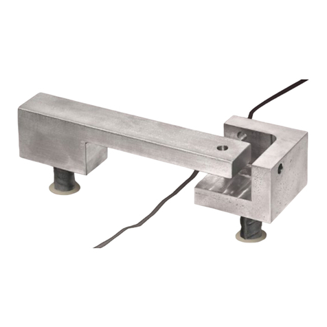
Geokon 4420 User manual

©2020,GEOKON. All rights reserved.
Document Revision: W | Release date: 8/4/20
Model 4420 Series
Vibrating Wire Crackmeter
Instruction Manual


WARRANTY STATEMENT
GEOKON warrants its products to be free of defects in materials and workmanship,
under normal use and service for a period of 13 months from date of purchase. If the
unit should malfunction, it must be returned to the factory for evaluation, freight
prepaid. Upon examination by GEOKON, if the unit is found to be defective, it will be
repaired or replaced at no charge. However, the WARRANTY IS VOID if the unit shows
evidence of having been tampered with or shows evidence of being damaged as a
result of excessive corrosion or current, heat, moisture or vibration, improper specifi-
cation, misapplication, misuse or other operating conditions outside of GEOKON's
control. Components that wear or are damaged by misuse are not warranted. This
includes fuses and batteries.
GEOKON manufactures scientific instruments whose misuse is potentially dangerous.
The instruments are intended to be installed and used only by qualified personnel.
There are no warranties except as stated herein. There are no other warranties,
expressed or implied, including but not limited to the implied warranties of merchant-
ability and of fitness for a particular purpose. GEOKON is not responsible for any
damages or losses caused to other equipment, whether direct, indirect, incidental,
special or consequential which the purchaser may experience as a result of the instal-
lation or use of the product. The buyer's sole remedy for any breach of this agreement
by GEOKON or any breach of any warranty by GEOKON shall not exceed the purchase
price paid by the purchaser to GEOKON for the unit or units, or equipment directly
affected by such breach. Under no circumstances will GEOKON reimburse the
claimant for loss incurred in removing and/or reinstalling equipment.
Every precaution for accuracy has been taken in the preparation of manuals and/or
software, however, GEOKON neither assumes responsibility for any omissions or
errors that may appear nor assumes liability for any damages or losses that result
from the use of the products in accordance with the information contained in the
manual or software.
No part of this instruction manual may be reproduced, by any means, without the written consent of GEOKON. The
information contained herein is believed to be accurate and reliable. However, GEOKON assumes no responsibility
for errors, omissions or misinterpretation. The information herein is subject to change without notification.
The GEOKON® wordmark and logo are registered trademarks with the United States Patent and Trademark Office.


I
TABLE OF CONTENTS
1. INTRODUCTION............................................................................................................................................1
2. INSTALLATION..............................................................................................................................................2
2.1 PRELIMINARY TESTS ......................................................................................................................2
2.2 CRACKMETER INSTALLATION ...............................................................................................2
2.2.1 ANCHORS .............................................................................................................................................2
2.2.2 INSTALLATION USING WELDABLE FIXTURES ....................................................................4
2.2.3 INSTALLATION USING GROUTABLE ANCHORS .................................................................4
2.2.4 INSTALLATION USING EXPANSION ANCHORS ..................................................................5
2.3 SPECIAL INSTALLATION NOTE..............................................................................................5
3. INSTRUMENT PROTECTION.........................................................................................................7
3.1 CABLE SPLICING AND TERMINATION ............................................................................7
3.2 PROTECTION FROM MECHANICAL DAMAGE...........................................................7
3.3 CABLE AND CONNECTOR PROTECTION........................................................................8
3.4 PROTECTION FROM CORROSION ........................................................................................8
3.5 PROTECTION FROM ELECTRICAL NOISE......................................................................8
3.6 PROTECTION FROM SUNLIGHT AND TEMPERATURE CHANGES .........8
3.7 LIGHTNING PROTECTION............................................................................................................8
4. TAKING READINGS ............................................................................................................................. 10
4.1 GK-404 VIBRATING WIRE READOUT............................................................................ 10
4.1.1 OPERATING THE GK-404 ........................................................................................................... 10
4.2 GK-405 VIBRATING WIRE READOUT............................................................................ 11
4.2.1 CONNECTING SENSORS WITH 10-PIN BULKHEAD CONNECTORS
ATTACHED ....................................................................................................................................... 11
4.2.2 CONNECTING SENSORS WITH BARE LEADS................................................................... 11
4.2.3 OPERATING THE GK-405 ........................................................................................................... 11
4.3 MEASURING TEMPERATURES ........................................................................................... 11
5. DATA REDUCTION ................................................................................................................................13
5.1 DISPLACEMENT CALCULATION........................................................................................ 13
5.2 TEMPERATURE CORRECTION ............................................................................................. 14
5.3 ENVIRONMENTAL FACTORS ................................................................................................ 15
6. TROUBLESHOOTING .......................................................................................................................... 16
APPENDIX A. SPECIFICATIONS .................................................................................................. 17
APPENDIX B. THERMISTOR TEMPERATURE DERIVATION....................... 18

II
APPENDIX C. MODEL 4420HT – HIGH TEMPERATURE VERSION ..... 19
APPENDIX D. 3D MONITORING................................................................................................... 21
D.1 ARRAY OF 3 CRACKMETERS............................................................................................... 21
D.2 INSTALLING THE 3D ARRAY ................................................................................................ 21
D.3 MODEL 4420-3 CANTILEVER 3D ARRAY ALTERNATIVE............................ 23
APPENDIX E. MODEL 4420-3 LOW PROFILE CRACKMETER................... 25
E.1 INSTALLATION................................................................................................................................... 25
E.1.1 PRELIMINARY TESTS................................................................................................................... 25
E.1.2 CRACKMETER INSTALLATION ................................................................................................ 26
E.2 SPECIFICATIONS.............................................................................................................................. 27
E.3 THERMISTOR....................................................................................................................................... 28
E.4 TEMPERATURE CORRECTION FACTOR....................................................................... 28

III
FIGURES
FIGURE 1: MODEL 4420 VIBRATING WIRE CRACKMETER ............................................1
FIGURE 2: MODEL 4420-3, -12.5, -25 DETAILED VIEW .................................................1
FIGURE 3: ANCHOR TYPES WITH DIMENSIONS ............................................................3
FIGURE 4: INSTALLATION USING WELDABLE FIXTURES .............................................4
FIGURE 5: INSTALLATION USING GROUTABLE ANCHORS ...........................................4
FIGURE 6: INSTALLATION USING EXPANSION ANCHORS ...........................................5
FIGURE 7: TYPICAL COVER PLATE INSTALLATION ........................................................7
FIGURE 8: LIGHTNING PROTECTION SCHEME ...............................................................9
FIGURE 9: GK-404 READOUT .........................................................................................10
FIGURE 10: LEMO CONNECTOR TO GK-404 .................................................................10
FIGURE 11: GK-405 READOUT .......................................................................................11
FIGURE 12: TYPICAL CRACKMETER CALIBRATION SHEET .........................................14
FIGURE 13: TYPICAL 3D ARRAY - TOP VIEW ................................................................21
FIGURE 14: TYPICAL 3D ARRAY - FRONT VIEW ...........................................................21
FIGURE 15: CANTILEVER 3D ARRAY - TOP VIEW ........................................................23
FIGURE 16: CANTILEVER 3D ARRAY, FRONT VIEW .....................................................24
FIGURE 17: MODEL 4420-3 VW LOW PROFILE CRACKMETER LAYOUT ...................25
FIGURE 18: CRACKMETER ASSEMBLY USING REFERENCE DISK ..............................26
FIGURE 19: CRACKMETER ASSEMBLY WITH ONLY ONE ANCHOR ...........................26

IV
TAB LE S
TABLE 1: CRACKMETER ANCHOR SPACING DISTANCES ..............................................3
TABLE 2: CRACKMETER READING RANGES ....................................................................3
TABLE 3: DIMENSIONS OF EXTENDED RANGE COVERS ...............................................7
TABLE 4: ENGINEERING UNITS CONVERSION MULTIPLIERS .....................................13
TABLE 5: THERMAL COEFFICIENT CALCULATION CONSTANTS .................................15
TABLE 6: MODEL 4420 CRACKMETER SPECIFICATIONS.............................................. 17
TABLE 7: 3KΩ THERMISTOR RESISTANCE .....................................................................18
TABLE 8: MODEL 4420HT 10KΩ THERMISTOR RESISTANCE.......................................20
TABLE 9: 3D ARRAY, TYPICAL VERSION .........................................................................21
TABLE 10: 3D ARRAY, CANTILEVER VERSION...............................................................24
TABLE 11: MODEL 4420-3 CRACKMETER SPECIFICATIONS........................................27

V
EQUATIONS
EQUATION 1: DIGITS CALCULATION .............................................................................. 13
EQUATION 2: DISPLACEMENT CALCULATION.............................................................. 13
EQUATION 3: DISPLACEMENT CHANGE ....................................................................... 13
EQUATION 4: THERMALLY-CORRECTED DISPLACEMENT CALCULATION ................ 14
EQUATION 5: THERMAL COEFFICIENT CALCULATION ............................................... 14
EQUATION 6: 3KΩ THERMISTOR RESISTANCE............................................................. 18
EQUATION 7: MODEL 4420HT 10KΩ THERMISTOR RESISTANCE .............................. 19
EQUATION 8: DISPLACEMENT, CORRECTED FOR TEMPERATURE ............................ 28

VI

MODEL 4420 VIBRATING WIRE CRACKMETER | INTRODUCTION | 1
1. INTRODUCTION
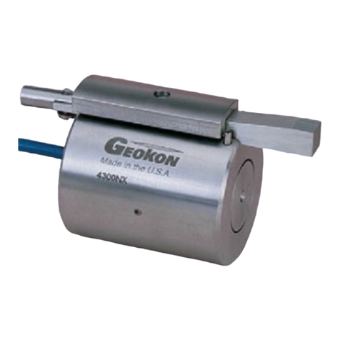
GEOKON Model 4420 vibrating wire crackmeters are designed to measure
movement across tension cracks in soils, joints in rock and concrete,
construction joints in buildings, bridges, pipelines, dams, and more.
The instrument consists of a vibrating wire sensing element in series with a heat-
treated, stress-relieved spring, which is connected to the wire at one end and to
a connecting rod at the other. The unit is fully sealed and operates at pressures
of up to 250 psi. As the connecting rod is pulled out from the gauge body, the
spring is elongated causing an increase in tension, which is sensed by the
vibrating wire element. The increase in tension (strain) of the wire is directly
proportional to the extension of the shaft. This change in strain allows the Model
4420 to measure the opening of the joint very accurately.
1:
FIGURE 1: Model 4420 Vibrating Wire Crackmeter
Models 4420-3, 4420-12.5, and 4420-25 differ slightly from the standard
crackmeter in that they provide for adjustment of the setting distance with a
threaded extension rod and locking nut.
2:
FIGURE 2: Model 4420-3, -12.5, -25 Detailed View
CAUTION! Do not rotate the shaft of the crackmeter more than 180 degrees:
Doing so may cause irreparable damage to the instrument. Use the alignment
pin on the transducer shaft and the slot on the body as a guide for alignment.
Never extend the crackmeter beyond its working range.

2| INSTALLATION | GEOKON
2. INSTALLATION
2.1 PRELIMINARY TESTS
Check the gauge for proper operation when you receive it. Check the thermistor
as well. The crackmeter normally arrives with its shaft secured at approximately
50% of its range.
For crackmeters with a range of 100 mm (4") or smaller, the shaft is secured
using a dowel pin held in place by a piece of tape (see Figure 1).
For crackmeters with a range greater than 100 mm, a slotted sleeve made of
PVC secures the shaft.
These devices hold the crackmeter in tension to protect it during shipping. With
the shipping spacers still in place, connect the gauge to a readout box and take
a reading. (See Section 4.1 for readout instructions.) The reading should be
stable and in the range of 4000 to 5000 digits. Please note that crackmeters with
a 3 mm (.125") range are shipped with the push rod fully retracted and have no
shipping spacer to remove. These gauges should read between 2000 to 3000
digits.
Check electrical continuity using an ohmmeter. Be sure to consider the
following:
■Resistance between the gauge leads should be approximately 180 ohms,
±10 ohms (128 ohms for the Model 4420HT).
■Remember to add the cable resistance, which is approximately 14.7Ωper
1000 ft. (48.5Ωper km) of 22 AWG stranded copper leads at 20 °C.
■Multiply this factor by two to account for both directions.
■Resistance between the green and white conductors will vary based on
temperature.
■For standard crackmeters, refer to Table 7 in Appendix B.
■For the 4420HT crackmeter, refer to Table 8 in Appendix C.
■Resistance between any conductor and the shield should exceed two
megohms.
Carefully remove the PVC slotted sleeve or dowel pin before proceeding further.
Hold the transducer shaft to prevent it from snapping into the transducer
housing.
2.2 CRACKMETER INSTALLATION
For additional instructions Models 4420HT and 4420-3, see Appendix C and
Appendix E respectively. For additional instructions regarding 3D Arrays, see
Appendix D.
2.2.1 ANCHORS
Three types of anchors are available:
■Weldable Mounting Fixture
■Expansion Anchor
■Groutable Anchor

MODEL 4420 VIBRATING WIRE CRACKMETER | INSTALLATION | 3
The weldable fixture is designed to aid in mounting the crackmeter on steel
members. The machine bolt expansion anchors and groutable anchors are used
to install the crackmeter on concrete or rock. The anchors are installed at the
appropriate spacing distance, depending on the anticipated direction of
movement (extension or compression). Refer to the table below.
3:
FIGURE 3: Anchor Types with Dimensions
Section 2.2.2 through Section 2.2.4 contain detailed instructions on each type of
anchor. Section 2.3 contains special instructions on the following models:
■4420-1-3 mm (.125")
■4420-1-12.5 mm (.5")
■4420-1-25 mm (1")
TABLE 1: Crackmeter Anchor Spacing Distances
When setting the gauge position using a portable readout, use the reading
ranges in the table below to determine the proper position.
TABLE 2: Crackmeter Reading Ranges
Be sure to consider the following:
■Note that the calibration sheet (see Figure 12) supplied with the crackmeter
shows factory readings at zero, 25%, 50%, 75%, and 100% of the range of
extension.
■These readings can be used as a guide to set the crackmeter in any part of
its range, either in anticipation of closure or opening of the crack.
■Extend the crackmeter until the desired reading is obtained.
Model & Range 1: Midrange To Monitor Extension To Monitor Compression
4420-3 mm (.125") 292.6 mm (11.52") 291.1 mm (11.46") 294.1 mm (11.58")
4420-12.5 mm (.5") 317 mm (12.5") 310 mm (12.2") 325 mm (12.8")
4420-25 mm (1") 343 mm (13.5") 330 mm (13") 356 mm (14")
4420-50 mm (2") 396 mm (15.6") 371 mm (14.6") 422 mm (16.6")
4420-100 mm (4") 554 mm (21.8") 503 mm (19.8") 605 mm (23.8")
4420-150 mm (6") 645 mm (25.4") 569 mm (22.4") 721 mm (28.4")
4420-200 mm (8") 869 mm (34.2") 767 mm (30.2") 970 mm (38.2")
4420-300 mm (12") 1186 mm (46.7") 1034 mm (40.7") 1339 mm (52.7")
Note for Model 4420HT: Due to the U-joint configuration of 4420HT, the overall gauge assembly length is increased by 35
mm (1.375"). This length should be added to the anchor spacing distance shown above.
Approximate Midrange Reading 2: Approximate Reading to Monitor
Extensions
Approximate Reading to Monitor
Compressions
4500-5000 2500-3000 6500-7000

4| INSTALLATION | GEOKON
■Hold the crackmeter in this position while the distance between the cap
screws is measured (set inside the swivel bearings, see Figure 1).
■This measurement can serve as a spacing guide for drilling or welding the
anchor points.
■Use the alignment pin on the transducer shaft and slot on the body as a
guide for alignment.
■Do not rotate the shaft of the crackmeter more than 180 degrees.
Doing so may cause irreparable damage to the instrument.
2.2.2 INSTALLATION USING WELDABLE FIXTURES
4:
FIGURE 4: Installation using Weldable Fixtures
INSTALLATION INSTRUCTIONS:
1. Determine the proper setting distance using the spacings listed in Table 1.
2. Grind, sand, or otherwise prepare the surface of the steel around the area of
each weldable fixture.
3. Position the welding fixtures on prepared surfaces.
4. Verify the placement again, then tack weld to the member.
5. Remove the PVC slotted sleeve or dowel pin securing the transducer shaft.
6. Thread the cap screw through the swivel bearing and through the half-inch
spacer on each end.
7. Tighten the cap screws into the welding fixtures as depicted in Figure 4.
8. Check and record the reading with a portable readout. Use Table 2 or the
readings on the calibration sheet to check the position.
2.2.3 INSTALLATION USING GROUTABLE ANCHORS
5:
FIGURE 5: Installation using Groutable Anchors
INSTALLATION INSTRUCTIONS:
1. Determine the proper setting distance using the spacings listed in Table 1.

MODEL 4420 VIBRATING WIRE CRACKMETER | INSTALLATION | 5
2. Using a hammer drill (or other suitable equipment), drill two half-inch
diameter holes approximately three inches deep at the proper locations.
Shorter holes may be drilled if the anchors are cut down accordingly.
3. Push the cap screws through the swivel bearings and spacers on each end
of the crackmeter and then loosely thread them into the groutable anchors.
4. For midrange position installations, secure the transducer shaft in place by
leaving the PVC slotted sleeve or dowel pin installed.
5. Fill the holes three quarters full with grout or epoxy. For holes drilled
overhead use a quick setting grout or epoxy.
6. Push and twist the anchors in until the tops are flush with the surface. Wipe
any excess epoxy clear of the tops of the anchors.
7. After the grout or epoxy has set, install and tighten the set screws.
8. Remove the PVC slotted sleeve or dowel pin if it was not removed earlier.
9. Check and record the reading with a portable readout. Use Table 2 to check
and adjust the position as needed.
2.2.4 INSTALLATION USING EXPANSION ANCHORS
6:
FIGURE 6: Installation using Expansion Anchors
INSTALLATION INSTRUCTIONS:
1. Determine the proper setting distance using the spacings listed in Table 1.
2. Using a masonry drill (or other suitable equipment), drill two 10 mm (3/8")
diameter holes, 32 mm (1.25") deep at the proper locations.
3. Insert the expansion anchors into the holes, with the slotted end down.
4. Insert the setting tool into the anchor, small end first. Expand the anchor by
hitting the large end of the setting tool with several sharp hammer blows.
5. Remove the PVC slotted sleeve or dowel pin securing the transducer shaft.
6. Push the cap screws through the swivel bearings and spacers on each end
of the crackmeter and then tighten the cap screws into the anchors.
7. Check and record the reading with a portable readout. Use Table 2 to check
and adjust the position as needed.
2.3 SPECIAL INSTALLATION NOTE
Regarding Models 4420-1-3 mm (.125"), 4420-1-12.5 mm (.5"), and 4420-1-25
mm (1"), please keep the following in mind:
■If the reading is not in the proper range after installation, make adjustments
using the threaded extension at the end of the transducer shaft.
■To make accurate adjustments, attach the transducer to the anchor at the
cable end, and temporarily remove it from the opposite anchor.

6| INSTALLATION | GEOKON
TO MAKE AN ADJUSTMENT, DO THE FOLLOWING:
1. Loosen the locking nut and then rotate the threaded rod into or out of the
end of the transducer shaft.
Note: Grip the transducer shaft while rotating the threaded rod. Never
rotate the transducer shaft beyond 180 degrees, or gauge failure may result.
2. After making an adjustment, align the hole in the swivel bearing over the
anchor and check the reading.
3. Make adjustments until the desired reading displays on the readout.
4. Push the cap screw through the swivel bearing and spacer.
5. Tighten into the anchor.
6. Re-tighten the locking nut.

MODEL 4420 VIBRATING WIRE CRACKMETER | INSTRUMENT PROTECTION | 7
3. INSTRUMENT PROTECTION
3.1 CABLE SPLICING AND TERMINATION
Terminal boxes with sealed cable entries are available from GEOKON for all types
of applications. These allow many instruments to be terminated at one location
with complete protection of the lead wires. The interior panel of the terminal box
can have built-in jacks or a single connection with a rotary position selector
switch. Contact GEOKON for specific application information.
Because the vibrating wire output signal is a frequency rather than a current or
voltage, variations in cable resistance have little effect on instrument readings;
therefore, splicing of cables has no ill effects, and in some cases may in fact be
beneficial. The cable used for making splices should be a high quality twisted
pair type, with 100% shielding and an integral shield drain wire. When splicing,
it is very important that the shield drain wires be spliced together.
Always maintain polarity by connecting color to color.
Splice kits recommended by GEOKON incorporate casts that are placed around
the splice and are then filled with epoxy to waterproof the connections. When
properly made, this type of splice is equal or superior to the cable in strength
and electrical properties. Contact GEOKON for splicing materials and additional
cable splicing instructions.
Terminate a cable by stripping and tinning the individual conductors and then
connecting them to the patch cord of a readout box. Alternatively, use a
connector to plug directly into the readout box or to a receptacle on a special
patch cord.
3.2 PROTECTION FROM MECHANICAL DAMAGE
It is important that you protect the crackmeter from damage. GEOKON makes
steel cover plates, Model 4420-7, for this purpose. GEOKON makes them using
sheet steel formed into a channel shape. The standard cover plate is long
enough to cover the two-inch range crackmeter; longer range crackmeters use
multiple cover plates tack-welded together.
7:
FIGURE 7: Typical Cover Plate Installation
The mounting nut and washer should be tightened only loosely to enable the
cover to slide on the 3/8 threaded rods. An extra nut is provided as a locknut.
Critical dimensions of the extended range covers are shown in the table below.
TABLE 3: Dimensions of Extended Range Covers
Range 3: Total Length Hole Spacing Slot Lengths
100 mm (4") 36" 32.5" 2"
150 mm (6") 36" 31.5" 3"
200 mm (8") 48" 42.5" 4"
300 mm (12") 60" 52.5" 6"

8| INSTRUMENT PROTECTION | GEOKON
3.3 CABLE AND CONNECTOR PROTECTION
The cable should be protected from accidental damage caused by moving
equipment or fly rock. This is best accomplished by putting the cable inside
flexible conduit and positioning the conduit in as safe a place as possible.
(Flexible conduit is available from GEOKON.) The conduit can be connected via
conduit bulkhead connectors to the cover plates. (The GEOKON cover plate has a
stamped knockout which, when removed, provides a hole for connecting the
conduit connector.)
3.4 PROTECTION FROM CORROSION
It is imperative that installation weld points, if any, be protected from corrosion.
Stainless steel instruments will not corrode, but the substrate can corrode,
especially at weld points, unless they are covered by a waterproofing layer.
GEOKON recommends you follow this procedure:
1. Apply several drops of cyanoacrylate adhesive to the edge of all spot
welded mounting tabs. The glue will wick into the gap between the
mounting tabs and the substrate and provide the first line of defense.
2. Mask off the areas where spot welds are needed.
3. Spray a coat of self-etching primer (available at any auto parts store) over
mounting tab areas and all exposed bare metal areas. The idea is to protect
substrate weld points. It is important to completely cover mounting tab
edges, paying particular attention to the point where the tab is under the
instrument. Be sure to spray beneath the coil housing, if applicable; do not
worry if the primer also coats the instrument.
4. Apply a coat of paint over the primed areas.
3.5 PROTECTION FROM ELECTRICAL NOISE
Be sure to install instrument cables as far away as possible from sources of
electrical interference such as power lines, generators, motors, transformers, arc
welders, etc. Cables should never be buried or run with AC power lines. Doing
so will cause the instrument cables to pick up the frequency noise from the
power cable, and this will likely make obtaining a stable reading difficult.
3.6 PROTECTION FROM SUNLIGHT AND TEMPERATURE CHANGES
If attached to a steel structure, the thermal coefficient of expansion of the steel
vibrating wire inside the instrument is the same as that for the structure. This
means that no temperature correction for the measured strain is required when
calculating load-induced strains. However, this is only true if the wire and the
underlying steel structure are at the same temperature. If sunlight is allowed to
impinge directly onto the gauge, it could elevate the temperature of the wire
above the surrounding steel and cause large changes in apparent strain.
Therefore, always shield strain gauges from direct sunlight. Protection from
thermal effects is best provided by covering the gauges with a layer of insulating
material such as Polystyrene foam or fiberglass.
3.7 LIGHTNING PROTECTION
Unlike numerous other types of instrumentation available from GEOKON,
vibrating wire strain instruments do not have any integral lightning protection
components, such as transorbs or plasma surge arrestors.
SUGGESTED LIGHTNING PROTECTION OPTIONS:
■Lighting arrestor boards and enclosures are available from GEOKON. These
units install where the instrument cable exits the structure being monitored.

MODEL 4420 VIBRATING WIRE CRACKMETER | INSTRUMENT PROTECTION | 9
The enclosure has a removable top to allow the customer to service the
components or replace the board in the event that the unit is damaged by a
lightning strike. A connection is made between the enclosure and earth
ground to facilitate the passing of transients away from the instruments.
See the figure below.
■Plasma surge arrestors can be epoxied into the instrument cable, close to
the instrument. A ground strap then connects the surge arrestor to an earth
ground, such as a grounding stake or the steel structure.
Consult the factory for additional information on available lightning protection.
8:
FIGURE 8: Lightning Protection Scheme
Ground Connections
Terminal Box
or Multiplexer
Structure
Copper Ground Wire
Instrument Cable
(usually buried)
Lab3
Enclosure
Crack
Crackmeter

10 | TAKING READINGS | GEOKON
4. TAKING READINGS
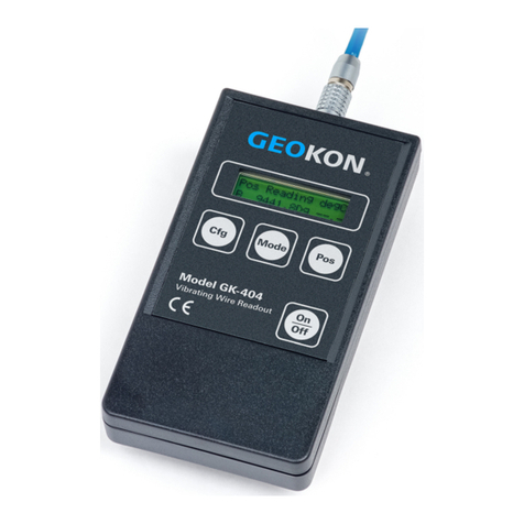
4.1 GK-404 VIBRATING WIRE READOUT
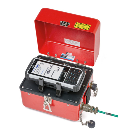
The Model GK-404 VW Readout is a portable, low-power, hand-held unit that is
capable of running for more than 20 hours continuously on two AA batteries. It
is designed for the readout of all GEOKON vibrating wire instruments, and is
capable of displaying the reading in digits, frequency (Hz), period (µs), or
microstrain (µε). The GK-404 also displays the temperature of the transducer
(embedded thermistor) with a resolution of 0.1 °C.
9:
FIGURE 9: GK-404 Readout
4.1.1 OPERATING THE GK-404
1. Attach the flying leads by aligning the red circle on the silver Lemo
connector with the red line on the top of the GK-404 (see Figure 10). Insert
the Lemo connector into the GK-404 until it locks into place.
2. Connect each of the clips on the leads to the matching colors of the sensor
conductors, with blue representing the shield (bare).
3. To turn on the GK-404, press the On/Off button on the front panel of the
unit. The initial startup screen will display.
4. After a delay, the GK-404 will start taking readings and display them based
on the settings of the Pos and Mode buttons.
The unit display (from left to right) is as follows:
■The current position: set by the Pos button, displayed as A through F.
■The current reading: set by the Mode button, displayed as a numeric value
followed by the unit of measure.
■Temperature reading of the attached instrument in degrees Celsius.
Use the Pos and Mode buttons to select the correct position and display units
for the model of equipment purchased.
The GK-404 will continue to take measurements and display readings until the
unit is turned off, either manually or by the Auto-Off timer (if enabled).
For more information, consult the GK-404 manual.
10:
FIGURE 10: Lemo Connector to GK-404
Other manuals for 4420
2
Table of contents
Other Geokon Measuring Instrument manuals

Geokon
Geokon 6165 User manual

Geokon
Geokon 4500S User manual

Geokon
Geokon 4700 User manual

Geokon
Geokon 4820 User manual

Geokon
Geokon GK-404 User manual

Geokon
Geokon 4050 User manual

Geokon
Geokon 4675LV User manual

Geokon
Geokon 4500MLP User manual

Geokon
Geokon 4910 User manual

Geokon
Geokon GK-405 User manual

Geokon
Geokon 3900 User manual

Geokon
Geokon 6350 User manual

Geokon
Geokon 4500 Series User manual

Geokon
Geokon 4415 User manual

Geokon
Geokon 1300 User manual

Geokon
Geokon 4200 Series User manual

Geokon
Geokon 4650 User manual

Geokon
Geokon 4500HT User manual

Geokon
Geokon 6150F User manual

Geokon
Geokon GK-604D User manual