Gewiss Chorus GW 90 856 User manual

1
KNX 6A shutter actuators - DIN rail mounting
Technical Manual
GW 90 856 GW 90 857

2
Contents
1Introduction................................................................................................................................................ 3
2Application ................................................................................................................................................. 3
2.1Association limits ............................................................................................................................... 3
2.2Priority of the received commands .................................................................................................... 3
3“Channel x general settings” menu............................................................................................................ 4
3.1Parameters ........................................................................................................................................ 5
4“Periods channel x” menu.......................................................................................................................... 8
4.1Parameters ........................................................................................................................................ 9
5“Louvres control channel x” menu........................................................................................................... 10
5.1Parameters ...................................................................................................................................... 10
6“Channel x automatic calibration” menu.................................................................................................. 12
6.1Parameters ...................................................................................................................................... 12
7“Channel x forced positioning” menu....................................................................................................... 14
7.1Parameters ...................................................................................................................................... 14
8“Channel x block” menu........................................................................................................................... 16
8.1Parameters ...................................................................................................................................... 16
9“Scenes channel x” menu........................................................................................................................ 18
9.1Parameters ...................................................................................................................................... 18
10“Channel x alarms” menu .................................................................................................................... 20
10.1Parameters ...................................................................................................................................... 20
11“Channel x automatic mode” menu ..................................................................................................... 25
11.1Parameters ...................................................................................................................................... 26
12Communication objects ....................................................................................................................... 31
12.1Communication object table ............................................................................................................ 31

3
1 Introduction
This manual describes the functions of the “KNX 2-channel shutter actuator” and the “KNX 4-channel
shutter actuator” (GW90856 and GW90857 respectively), and how they are set and configured with the aid
of the ETS configuration software.
2 Application
The GW90856 shutter actuator is used to command two separate groups of motors, each with a maximum of
two 230V ac motors. The motors belonging to the same group are commanded at the same time.
The GW90857 shutter actuator has 4 independent outputs for commanding four separate 230V ac motors.
For each output there is a pair of contacts for the command and movement in one direction or the other (the
up or down movement of the shutter in question).
The outputs for up and down commands are mechanically interlocked together in order to prevent voltage
from being applied at the same time to both.
The GW90856 and GW90857 actuators are configured in System configuration mode (ETS).
2.1 Association limits
The maximum number of communication objects available is 52 for the GW90856 and 104 for the GW90857.
The maximum number of associations that the devices can store is 255.
The maximum number of group addresses is 254.
2.2 Priority of the received commands
The priority of the functions is shown in the following table:
Function Priority
Ch.x - Movement 1 low
Ch.x - Stop (/Louvres adjustment) 1
Ch.x - Position control 1
Ch.x - Louvre position control 1
Ch.x - Scene 1
Automatic calibration 2
Automatic mode 3
Weather alarms 4
Block 5
Forced positioning 6
Front keys (test function) 7
Actuator behaviour at bus voltage recovery 8
Alarm status when BUS voltage is reset 9
Value of block object when BUS voltage is reset 10
Forced positioning status on bus voltage recovery 11
230V voltage fall status (stop/no action) 12
Status at bus voltage drop (stop/no action) 12 high

4
3 “Channel x general settings” menu
Used to configure the operating parameters, as shown in Fig. 3.1.
Fig. 3.1

5
3.1 Parameters
3.1.1 Operating mode
Determines the device operating mode, by means of the following values:
Shutter
This is the default setting. If selected, it determines specific parameters and communication objects.
Venetian blind
This option is an alternative to the one above. It adds further parameters and different communication
objects.
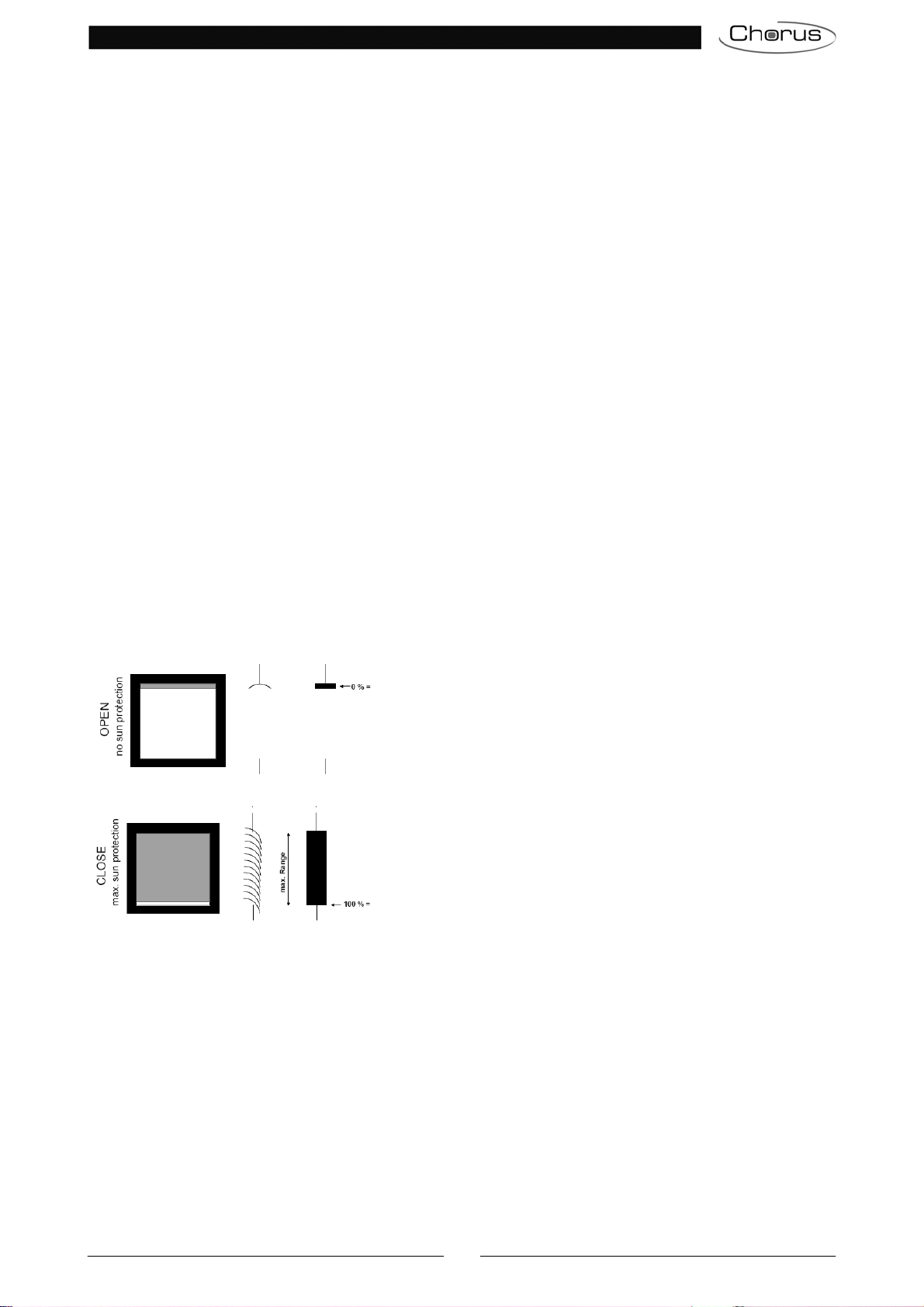
The Shutter and Venetian blind values are associated with a communication object that stops their
movement, but is different for each one; if shutter is selected, the object is “Ch.x - Stop”, but if venetian
blind is selected, the object is “Ch.x - Louvre stop/control”. If any value is received on both objects while
the load is moving, the movement will stop immediately; in the case of “shutter”, no action is performed if the
object is received when the load is not moving, but in the case of “venetian blind”, there will be an opening
control step (if the object has a value of “0”) or a closure control step (if the value is “1”).
If “venetian blind” is selected, the “Louvre control channel x” menu will appear.
Via the “Ch.x - Movement” communication object (always visible), it is possible to move the shutter or
venetian blind up or down, then stop it via the Ch.x - Stop (or Louvre stop/control) object, or at the end of the
set movement time.
3.1.2 Local keys behaviour
The behaviour of the local keys relating to channel x depends on the setting of the parameter, which may
have the following values:
disabled
this is the default value, with the local keys inhibited.
test (up/down/stop-step)
in this case, every time there is a long operation on the upper front key (>500 ms), the actuator moves
the load upwards. With a short operation (<500 ms), the load is stopped or the louvre opening is
controlled (if the set mode is “venetian blind”); the long operation of the lower front key involves a
downward movement of the load, whereas a short operation of the key will stop or close the louvres of
the load (if “venetian blind” is set). This command has top priority and is executed whatever the value of
the communication objects (including the objects “Ch.x - Priority command” and “Ch.x - Block”).
as communication objects (up/down/stop-step)
the function is as described above, with the main difference that an operation on the front keys emulates
the arrival of the communication objects Ch.x - Movement and Ch.x - Stop (or Louvre stop/control); this
implies that the actual execution of the commands only takes place if the functions with a higher priority
(Block, Forced positioning, etc.) are deactivated.
automatic calibration execution
pressing the two front keys simultaneously, the actuator immediately performs the automatic calibration
(for further details, refer to paragraph 6).
Selecting the item “execution of automatic calibration”, a dummy parameter is visualised with the note
“NOTE: for the calibration, push both buttons at the same time”.
3.1.3 Movement of the shutter/venetian blind without bus voltage
For the 4-channel version only (GW90857), if the device is powered with the auxiliary network voltage
(230V ac), the load can be moved via the front keys even if there is no bus voltage, using the 230V ac
network voltage (and enabling this parameter, which is disabled by default).
If “enabled” is selected, with a network voltage but no bus voltage, it is still possible to move the load via
the front keys of the device. In this particular condition, the value set for the “Local keys behaviour”
parameter is ignored and a long operation on the upper front key (>500 ms) causes the upward
movement of the load, while a short operation (<500 ms) causes the stopping or louvre opening control
(if the set mode is “venetian blind”); the long operation of the lower front key involves a downward

6
movement of the load, whereas a short operation of the key will stop or close the louvres of the load (if
"venetian blind” is set).
3.1.4 Percentage position command object
With this parameter it is possible to enable the communication object via which you can set the
percentage position of the shutter/venetian blind, leaving the actuator to perform the necessary
movement; this function is disabled by default.
If “enabled” is selected, the “Ch.x - Position control” communication object is visualised. With this, you
can receive the command with the percentage position value to be used for the implementation.
3.1.5 Percentage position feedback object
The device can signal the percentage position of the load controlled by each channel following a
movement, on the basis of the setting for this parameter, which may have the following values:
disabled
This is the default setting. The “Ch.x - Position feedback” object is not activated.
enabled only on demand
This option enables the “Ch.x - Position feedback” object, via which the device signals the percentage
position of the load.
enabled on variation and on switching on
This option enables the “Ch.x - Position feedback” object, via which the device signals the percentage
position of the load.
The transmission of the object occurs every time there is a variation in the position of the load and the
bus voltage is restored.
With regard to the percentage position of the object, the following convention is used:
o0% shutter/venetian blind completely raised
o100% shutter/venetian blind completely lowered
Here is an example:
Upper limit position
Lower limit position
Venetian blind Shutter
3.1.6 Movement in progress feedback object
This makes it possible to enable movement in progress signalling object using this parameter, which can
assume the following values:
disabled
This is the default setting. The “Ch.x - Movement feedback” object is not activated.
enabled only on demand
This option enables the “Ch.x - Movement feedback” object, via which the device signals with a value
equal to “1” that a downward movement of the load is in progress and with a value equal to “0” that an
upward movement is in progress.

7
enabled on variation
This option enables the “Ch.x - Movement signalling” object, via which the device signals with a
value equal to “1” that a downward movement of the load is in progress and with a value equal to “0” that
an upward movement is in progress.
The transmission of the communication object occurs every time there is a load movement.
3.1.7 Channel x behaviour at download
With this parameter, it is possible to define the behaviour of channel x following the download of the
application from the ETS software. By default, the parameter is set as no effect, but you can change this
to automatic calibration execution (for further details, refer to paragraph 6).
3.1.8 Channel x behaviour on BUS voltage recovery
The behaviour of channel x when the BUS voltage is restored is determined by this parameter, which
may have the following values:
No effect
This is the default setting.
Up movement
This option applies an upward movement.
Down movement
This option applies a downward movement.
Automatic calibration execution
This option makes an automatic calibration (for further details, refer to paragraph 6).
Percentage position
By selecting the “percentage position” value, the following parameters are visualised:
oPercentage position on bus voltage recovery with the possibility to set a percentage from 0 to
100, in 5% steps; the default value is 0%.
oLouvres percentage position on bus voltage recovery if the set mode is “venetian blind”,
with the possibility to set a percentage from 0 to 100, in 5% steps; the default value is 0%.
Before going to the desired position, the actuator automatically executes the calibration operation.
3.1.9 Travel limits
In some applications, it is useful to limit the object travel to a certain interval, to prevent it from being
damaged or damaging other objects; this parameter enables the limiting of the load travel via the “Ch.x -
Travel limits enabling” communication object, which may have the following values:
disable
This is the default setting. The “Ch.x - Travel limits enabling” object is not activated.
enable
This option visualises both the “Ch.x - Travel limits enabling”, “Ch.x - Upper travel limit”, “Ch.Y -
Lower travel limit” communication objects and the “Upper limit percentage position” and “Lower
limit percentage position” parameters; with the latter, you can set the interval limits for the load travel
once the limit has been enabled via the “Ch.x - Travel limits enabling” object.
The values that can be set are percentages from 0 to 100, in 5% steps; 0% is the upper limit default
value and 100% is the lower limit default value.
The travel limits can be modified via the “Ch.x - Upper travel limit” and “Ch.x - Lower travel limit”
communication objects.

8
If “enable” is set for “Travel limits”, you can also define the initial value of the “Ch.x - Travel limits
enabling” object when downloaded from ETS (via the “Travel limits enabling object value at
download” parameter) and on bus voltage recovery (via the “Travel limits enabling object value at
bus voltage recovery” parameter). The values that can be set for the latter are:
odisabled
This is the default setting. The “Ch.x - Travel limits enabling” object assumes a value of 0.
oenabled
The “Ch.x - Travel limits enabling” object assumes a value of 1.
oas before voltage drop
The “Ch.x - Travel limits enabling” object assumes the value set before the voltage drop.
The travel limits are only used for movements initiated by the communication object, with a priority level
lower than the weather alarms (see the table in paragraph 2.2).
4 “Periods channel x” menu
The Periods channel x menu contains the parameters shown in figure 4.1.
Fig. 4.1

9
4.1 Parameters
4.1.1 Travel range time [s]
The device calculates the percentage positions and executes partial movements based on the total load
travel time, which is the time the load requires to move from the “fully up” position (0%) to the “fully
closed” position (100%); this value is set in this parameter, and may assume a value from 1 to 3000 (the
default value is 180).
4.1.2 Movement time
Normally the device continues to power the motor contact even if the limit switch has been reached, to
make sure that the load has reached the limit switch position. You can set a time-out value with this
parameter, which may have the following values:
= Travel range time
= Travel range time + 2%
= Travel range time + 5%
= Travel range time + 10% (default value)
= Travel range time + 20%
4.1.3 Stop time for reversing [ms]
To prevent damaging the motor, a delay must be entered between receiving a command for movement
in the opposite direction of the current movement and the effective reversal of direction; this time is
normally provided by the shutter/venetian blind manufacturer and must be rigourously observed. This
parameter is therefore used to set values from 50 to 10000 (the default value is 600).
4.1.4 Motor start time [x 10 ms]
With a view to keeping the correct load positioning unaltered over time (following the execution of scenes
or percentage value commands), and to avoid any possible motor start-up delay (between the moment
when the motor is powered and the moment when it starts running), it is possible to apply an extension
of the time calculated to reach the required percentage position; this value can be set via this parameter,
which may assume values from 0 (default) to 255.
4.1.5 Motor deceleration time [x 10 ms]
In addition, certain motors continue running for a short time even when the power supply has been
switched off. With this parameter, you can set a time value to be subtracted from the time calculated to
reach an intermediate percentage position (requested by the user), so the control is more precise. The
values that can be set range from 0 (default) to 255.
The times set in the “Motor start time [ms]” and “Motor deceleration time [ms]” parameters are only used to
calculate the time needed to reach a certain intermediate percentage position (following a specific command
or the reproduction of a position associated with a scene, or prior to a feedback); they are not applied to any
movements made via the “Ch.x - Movement” object. The factor set for the above listed parameters must be
multiplied by 10 milliseconds.
Motor power
su
pp
l
y
moment
Motor power supply
time Motor deceleration
time
Movement start Movement end
Motor power supply
cut-off moment

10
5 “Louvres control channel x” menu
The Louvres control channel x menu contains the parameters shown in figure 5.1.
Fig. 5.1
5.1 Parameters
5.1.1 Louvres control operation step time (n x 100ms)
If the user sets “venetian blind” as the channel x operating mode, the Louvres control channel x
configuration menu will be visualised. With the “Louvre control operation step time (n x 100ms)”
parameter, you can set the factor which, multiplied by the base (100 milliseconds), indicates the duration
of the louvre control from “fully open” to “fully closed”. The values that can be set range from 1 to 120 (12
is the default value).
5.1.2 Define the louvres control step length by
This parameter defines whether the duration of a louvre control step is set in terms of time, or in terms of
the number of steps needed to pass from louvres "fully open" to "fully closed".
The parameter may have the values:
control impulse length
This is the default value which draws up the “Louvre control operation step time (n x
100ms)” parameter. Here, you can set the factor which, multiplied by the base (100
milliseconds), indicates the motor powering time corresponding to one louvre control step. The
values that can be set range from 1 to 120 (the default value is 3).
number of control impulses
In this case, the “Number of steps for total closing/opening of louvres” parameter will
appear. The values that can be set range from 1 to 15 (the default value is 4).

11
5.1.3 Louvres percentage control object
It is possible to regulate the louvres position by setting from the bus the percentage value to which they
should be brought according to the following convention:
0% louvres completely open
100% louvres completely closed
If enabled is set, then the “Ch.x - Louvre control command” communication object is visualised and
allows the percentage control of the louvres from the BUS.
5.1.4 Louvre percentage position feedback object
This makes it possible to enable the louvres percentage position signalling, which can assume the
following values:
disabled
This is the default setting. The “Ch.x - Louvres position feedback” communication object is
not activated.
enabled only on demand
The “Ch.x - Louvres position feedback” communication object is visualised. It is only sent
upon request.
enabled on variation and on switching on
The “Ch.x - Louvres position feedback” communication object is visualised. It is sent every
time there is a variation in the louvre position, and when the bus voltage is restored.
5.1.5 Louvres automatic movement at movement end at stop command
The device can be configured so the louvre control is automatically performed at the end of a movement
following the arrival of a stop command.
This parameter may have the following values:
disabled
this is the default value.
enabled
this displays both the parameter “Louvres percentage position after downward movement”
which makes it possible to set the percentage value of the louvres after a downward movement,
as well as the parameter “Louvres percentage position after upward movement” which
makes it possible to set the percentage value after an upward movement. The percentage
values range from 0 to 100 (50% is the default).
enabled after movement up
this is used to set the percentage value after an upward movement via the parameter “Louvres
percentage position after upward movement”. The percentage values range from 0 to 100
(50% is the default).
enabled after movement down
this is used to set the percentage value after a downward movement via the parameter
“Louvres percentage position after downward movement”. The percentage values range
from 0 to 100 (50% is the default).
5.1.6 Louvres automatic movement after percentage position command
This sets the automatic control of the louvres after the execution of a percentage position movement
command. It may assume the following values:
disabled
this is the default value.
enabled
this displays both the parameter “Louvres percentage position after downward movement”
which makes it possible to set the percentage value of the louvres after a downward movement,
as well as the parameter “Louvres percentage position after upward movement” which
makes it possible to set the percentage value after an upward movement. The percentage
values range from 0 to 100 (0% is the default).
enabled after movement up
this is used to set the percentage value after an upward movement via the parameter “Louvres
percentage position after upward movement”. The percentage values range from 0 to 100
(0% is the default).
enabled after movement down

12
this is used to set the percentage value after a downward movement via the parameter
“Louvres percentage position after downward movement”. The percentage values range
from 0 to 100 (0% is the default).
6 “Channel x automatic calibration” menu
The Channel x automatic calibration menu contains the parameters shown in figure 6.1.
Fig. 6.1
6.1 Parameters
6.1.1 Execute automatic calibration
The actuator calculates the percentage position of the connected load based on the travel range time set
by the user and in function of the movement commands it executes. Even if the parameters that
determine the operating times are precisely set, there may still be little variations between the position
calculated by the actuator and the real position, due for example to climate conditions or the mechanical
load tolerance.
The device can zero out these variations by executing movements towards the reference positions, that
is towards those identified by the two limit switches. Once the device executes a movement to the limit
switch, the movement times can be correctly recalculated and any misalignment errors are cancelled.
The device performs this operation every time the end stop is reached, but you can activate an
automatic calibration by means of the “Execute automatic calibration” parameter, which may assume
the following values:
never or downloading or bus voltage recovery
this is the default setting. It is selected when you do not want to perform an automatic calibration
apart from at the time of the download, or when the bus voltage is restored (in accordance with
the settings of the “Channel x behaviour at download” and “Channel x behaviour on BUS
voltage recovery” parameters).

13
after n movements
it is possible to define after how many movements the device must perform an automatic
calibration; each time the device reaches the limit switch, the movement counter is reset. The
values that can be set range from 1 to 30 (the default value is 10).
at trigger reception
the “Ch. x - Automatic calibration trigger” communication object is visualised. If the value is
“0” or “1”, the device interprets this as a command to perform the automatic calibration.
The enabling of this mode also activates the “Reference position” parameter, where you can
define which end stop the device must use as a reference for the automatic calibration. The
available values are:
otravel upper end (0%) (default value)
otravel lower end (100%)
When the calibration operation has been completed, it is possible to define the behaviour of the
device by means of the “Behaviour at the end of automatic calibration” parameter which, in
turn, may assume the following values:
ostays in the reference position (default value)
oback to previous position
opercentage position
in this case, the “Percentage position at the end of automatic calibration” parameter
is visualised (this defines the percentage position of the shutter) and, if the "venetian
blind" mode is set, the “Louvre percentage position at the end of automatic
calibration” parameter is also visualised (to define the percentage position of the
venetian blind louvres at the end of the automatic calibration). The percentage values
that can be set for both parameters range from 0 to 100 (the default value is 50%).
after n movements and at trigger reception
this option simultaneously activates both the modes (described above) - “after n movements”
and “on trigger reception”.

14
7 “Channel x forced positioning” menu
By activating the “Forced positioning function” in the General settings menu of the relative channel, the
“Ch.x - Priority command” communication object will be visualised. In addition, the Channel x forced
positioning menu will appear, with the parameters shown in figure 7.1.
Remember that the forced positioning activation command has a higher priority than any other bus
command, including the block function.
Fig. 7.1
7.1 Parameters
7.1.1 Behaviour on forced positioning deactivation
This parameter is used to set the behaviour of the actuator when the forced positioning function is
deactivated. The values that can be set are:
no effect
this is the default value. There is no action when the forced positioning function is deactivated.
up movement
when the forced positioning function is deactivated, an upward movement is commanded.
down movement
when the forced positioning function is deactivated, a downward movement is commanded.
back to previous position
when the forced positioning function is deactivated, the actuator returns to the previous position.
follows last command received
when the forced positioning function is deactivated, the valid command is the last one received.
percentage position
when the forced positioning function is deactivated, the “Percentage position when
deactivating forced positioning” parameter is visualised. This is used to select the required
value; the percentage values that can be set range from 0 to 100 in 5% steps and with a default
value of 50%.

15
If the operating mode is “venetian blind”, then the “Louvres percentage position when forced
positioning is deactivated” parameter is also visualised. This is used to select the required
value; the percentage values that can be set range from 0 to 100 in 5% steps and with a default
value of 50%.
stop
when the forced positioning function is deactivated, a stop is commanded.
7.1.2 Forced positioning status on bus voltage recovery
This parameter is used to determine the forced positioning status when the bus voltage is restored. It is
useful if the function is active when the bus voltage drops and you want to have the actuator behaviour
not be changed after voltage failure. The parameter may assume the following values:
deactivated
the forced positioning function is deactivated when the bus voltage is restored. If forced
positioning was active before the bus voltage drop, then when the bus voltage is restored the
forcing function is deactivated and the actuator observes the setting of the “Behaviour on forced
positioning deactivation” parameter.
as before bus voltage drop
this is the default value. If forced positioning was active before the bus voltage drop, then when
the bus voltage is restored the forcing function is reactivated and the actuator reproduces the
position prior to the voltage drop.

16
8 “Channel x block” menu
By activating the “Block function” in the General settings menu of the relative channel, you can block the
device in a specific condition (settable) following the arrival of the “Ch.x - Block” communication object
which activates the block function itself. Until this function is deactivated, no other command received on any
communication object is executed (apart from the forced positioning activation command).
The activation of the block function enables the Channel x block menu, containing the parameters shown in
figure 8.1.
Fig. 8.1
8.1 Parameters
8.1.1 Block activation value
This function determines the logic value with which the block function is activated via the “Ch.x - Block”
object; the value opposite of the set value will deactivate the function. The values that can be set are:
value “0”
the block function is activated with a value of 0, and deactivated with a value of 1.
value “1”
this is the default value. The block function is activated with a value of 1 and deactivated with a
value of 0.
8.1.2 Action on active block
During the block, it is possible to use this parameter to set the behaviour of the actuator channel. The
following values can be set:
no effect
this is the default value. No action is performed when the block function is activated.
up movement
when the block function is activated, an upward movement is commanded.
down movement

17
when the block function is activated, a downward movement is commanded.
percentage position
this option visualises the “Percentage position with block activated” parameter, used to
define the percentage position of the load. If the operating mode is "venetian blind", then the
“Louvre percentage position with block activated” parameter is also visualised. This is used
to define the percentage position of the venetian blind louvres; the percentage values that can
be set for both range from 0 to 100 in 5% steps and with a default value of 50%.
Stop
when the block function is activated, a stop is commanded.
8.1.3 Channel x behaviour on block deactivation
When the block function is deactivated, it is possible to use this parameter to set the behaviour of the
actuator channel. The following values can be set:
no effect
this is the default value. No action is performed when the block function is deactivated.
up movement
when the block function is deactivated, an upward movement is commanded.
down movement
when the block function is deactivated, a downward movement is commanded.
percentage position
this option visualises the “Percentage position on block deactivation” parameter, used to
define the percentage position of the load. If the operating mode is "venetian blind", then the
“Louvres percentage position on block deactivation” parameter is also visualised. This is
used to define the percentage position of the venetian blind louvres; the percentage values that
can be set for both range from 0 to 100 in 5% steps and with a default value of 50%.
stop
when the block function is deactivated, a stop is commanded.
8.1.4 Block object value at download
This parameter is used to set the logic value for the “Ch.x - Block” communication object upon ETS
download. The possible values are:
deactivated
this is the default value. The block is deactivated after the ETS download.
active
the block function is activated after the ETS download.
8.1.5 Block object value at bus voltage recovery
This parameter is used to set the logic value for the “Ch.x - Block” communication object whenever the
bus voltage is restored. The possible values are:
deactivated
the block function is deactivated when the bus voltage is restored.
active
the block function is activated when the bus voltage is restored.
as before voltage drop
this is the default value. The block function returns to the condition set before the bus voltage
drop.

18
9 “Scenes channel x” menu
By activating the “Scenes function” in the General settings menu of the relative channel, you can enable
this function that allows you to repeat a specific pre-set or previously stored position whenever the “Ch.x -
Scene” communication object is received. The device is able to memorise and execute 8 scenes.
The activation of the scenes function enables the Scenes channel x menu, containing the parameters
shown in figure 9.1.
Fig. 9.1
9.1 Parameters
9.1.1 Scene number 1..8
If the scenes function is activated, both the “Ch.x - Scene” input communication object (for receiving the
scene execution/storage commands) and the “Scenes channel x” configuration menu (with the relative
parameters) are received.
The “Scene number 1..8” parameters are used to set the numerical value for identifying and therefore
executing/storing the nth scene. The possible values are:
unassigned
this is the default value. No number is assigned to the scene in question.
0, 1, ..., 63
a number from 0 to 63 is assigned to the scene. The maximum number of scenes that can be
stored for each channel is 8.

19
The “Initial position scene 1..8” parameters are used to define the percentage position of the load
linked to channel x, and which the actuator must repeat when it receives the communication object for
the execution of the nth scene; the percentage values it can assume range from 0 to 100, in 5% steps.
The respective default values are: 0% (default value for scene 1)
15% (default value for scene 2)
30% (default value for scene 3)
45% (default value for scene 4)
60% (default value for scene 5)
75% (default value for scene 6)
90% (default value for scene 7)
100% (default value for scene 8)
If the “venetian blind” operating mode is set, “Louvre initial position scene 1..8” defines the position of
the blades of the load linked to channel x, and which the actuator must repeat when it receives the
communication object for the execution of the nth scene; the values it can assume range from 0 to 100 in
5% steps, and for all 8 scenes the default value is 0%.
9.1.2 Scene storing enabling
This parameter is used to enable/disable scene storing via the Ch.x - Scene communication object. The
parameter may assume the following values:
disabled
scene storing is not possible.
enabled
this is the default value. It visualises the “Ch.x - Scene storing enabling” communication
object, used to enable/disable - via bus - the possibility to store scenes by means of the “Ch.Y -
Scene” communication object.
Scene storing includes memorising the percentage position of the louvres (for venetian blinds). Therefore,
executing a scene must also include reproducing the previously memorised louvres position.

20
10 “Channel x alarms” menu
By activating the “Alarms function” in the General settings menu of the relative channel, you can enable
this function that allows you to avoid any weather-related damage to the load connected to the actuator.
There is a specific “Channel x alarms” configuration menu for enabling special communication objects that
interface with weather sensors (rain sensor, wind sensor, etc.).
The activation of the alarms function enables the Channel x alarms menu, containing the parameters shown
in figure 10.1.
Fig. 10.1
10.1Parameters
10.1.1 Number of objects enabled for wind alarm
This parameter can be used to define how many communication objects the user wants to use to monitor
the wind; up to 3 values can be set (the default setting is 0).
Depending on the number of objects enabled, the “Ch.x - Wind alarm 1..3” communication objects and
the “Wind alarm 1..3 activation value” parameters will be visualised; the latter define the activation
value for the communication object associated with the wind alarm. The values that can be set are:
value “0”
the relative wind alarm is activated with a value of 0.
This manual suits for next models
1
Table of contents
Other Gewiss Controllers manuals

Gewiss
Gewiss Chorus GW 10 766 User manual

Gewiss
Gewiss Chorus GWA1521 User manual

Gewiss
Gewiss CHORUS GW 13 766 User manual

Gewiss
Gewiss zigbee CHORUS GWA1531 User manual

Gewiss
Gewiss Chorus GW 10 568 User manual

Gewiss
Gewiss Chorus GW 90 852 User manual

Gewiss
Gewiss Chorus GW 90 836A User manual

Gewiss
Gewiss CHORUS GWA9140 User manual

Gewiss
Gewiss Chorus GW 10 766 User manual

Gewiss
Gewiss Chorus GWA1521 User manual