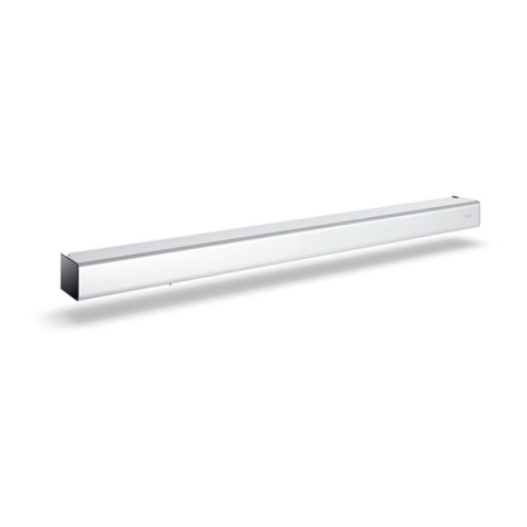
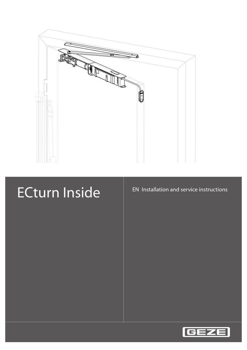
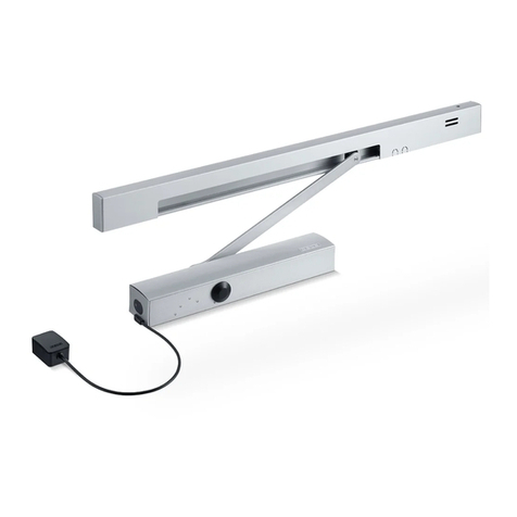
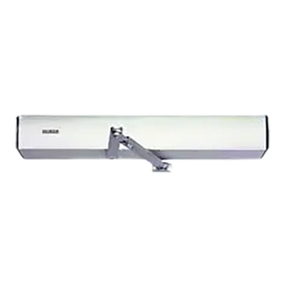
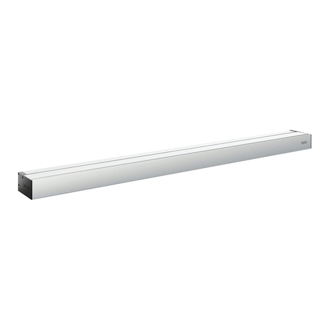
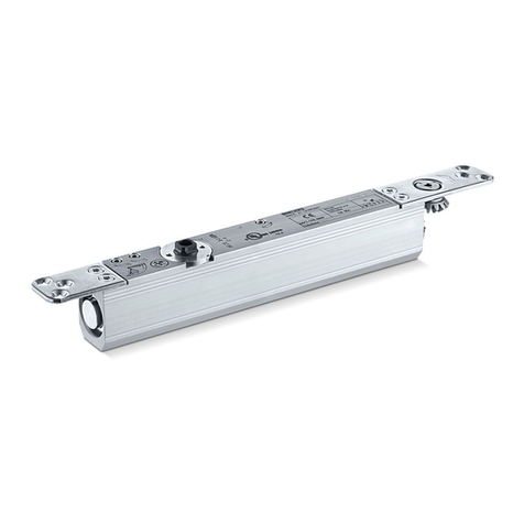
GEZE ECturn User manual

1
ECturn GB Mounting instructions

ECturn
2
Contents
1 Symbols and means of representation............................................................................................................3
2 Product liability ........................................................................................................................................................3
3 Safety ...........................................................................................................................................................................3
3.1 Intended use.......................................................................................................................................................................................................3
3.2 Safety instructions ...........................................................................................................................................................................................4
3.3 Safety-conscious working.............................................................................................................................................................................4
3.4 Inspection of the mounted system............................................................................................................................................................4
3.5 Additionally applicable documents ..........................................................................................................................................................4
4 Transportation and storage .................................................................................................................................5
5 Tools and aids ...........................................................................................................................................................5
6 Product description ................................................................................................................................................5
6.1 System description and technical data ....................................................................................................................................................5
6.2 Basic structure and extension......................................................................................................................................................................6
7 Types of mounting, stops .....................................................................................................................................8
8 Mounting ...................................................................................................................................................................9
8.1 General information for mounting ............................................................................................................................................................9
8.2 Mounting dimensions for the types of mounting ............................................................................................................................ 10
8.3 Mounting the drive....................................................................................................................................................................................... 16
8.4 Mounting the guide rail .............................................................................................................................................................................. 16
8.5 Mounting the link arm................................................................................................................................................................................. 16
8.6 Door stop limiting ..........................................................................................................................................................................................17
8.7 Mounting and connecting the battery ..................................................................................................................................................17
8.8 Mounting the door transmission cable (optional) .............................................................................................................................18
8.9 Mounting the hood (optional)...................................................................................................................................................................19
8.10 Mounting the actuation sensors...............................................................................................................................................................19
8.11 Mounting the radio circuit board (optional) ........................................................................................................................................19
9 Electrical connection............................................................................................................................................19
9.1 Mains connection...........................................................................................................................................................................................19
10 Maintenance........................................................................................................................................................... 21
10.1 Dangers during mechanical service....................................................................................................................................................... 21
10.2 Maintenance work......................................................................................................................................................................................... 21
10.3 Electrical servicing ........................................................................................................................................................................................ 21
10.4 Electrical faults................................................................................................................................................................................................ 22
11 Disposal.................................................................................................................................................................... 22

ECturn
3
Symbols and means of representation
Symbols and means of representation1
Warnings
In these instructions, warnings are used to warn against material damage and injuries.
Always read and observe these warnings.
X
Observe all the measures that are marked with the warning symbol and warning word.
X
Warning
symbol
Warning word Meaning
WARNING Danger for persons.
Non-compliance can result in death or serious injuries.
CAUTION Danger for persons.
Non-compliance can result in minor injuries.
– CAUTION Information on avoiding material damage, understanding a concept or optimising the
processes.
Further symbols and means of representation
Important information and technical notes are emphasised in order to illustrate the correct operation.
Symbol Meaning
means "important note"
means "additional information"
X
Symbol for an action: Here you have to do something.
Observe the sequence if there are several action steps.
X
Product liability2
In accordance with the liability of the manufacturer for his products as dened in the German "Produkthaftungs-
gesetz" (Product Liability Act), the information contained in this brochure (product information and proper use,
misuse, product performance, product maintenance, obligations to provide information and instructions) is to be
observed. Non-compliance releases the manufacturer from his statutory liability.
Safety3
Intended use3.1
The ECturn swing door drive is designed for the automatic opening and closing of swing-door single action
doors.
The ECturn swing door drive is suitable:
solely for use in dry roomsà
in entrances and interior areas of pedestrian trac in commercial plants and public areasà
in private areas.à
The ECturn swing door drive
may not be used at re or smoke proof doors,à
may not be used for hazardous areas.à
Any other use than the proper use, such as permanent manual operation, as well as all changes to the product
are impermissible.

ECturn
4
Safety
Safety instructions3.2
The prescribed mounting, maintenance and repair work must be performed by properly trained personnelà
authorised by GEZE.
The country-specic laws and regulations are to be observed during safety-related tests.à
GEZE shall not be liable for injuries or damage resulting from unauthorised modication of the system.à
GEZE shall not be liable if products from other manufacturers are used with GEZE equipment.à
Only original GEZE parts may be used for repair and maintenance work as well.à
The connection to the power supply must be made by a professional electrician. Perform the power connec-à
tion and safety earth conductor test in accordance with DIN VDE 0100-610.
Exception: If the ECturn swing door drive is connected to the mains voltage by the mounted power plug, the
connection does not have to be carried out by a qualied electrician.
Use a customer-accessible 10-A automatic circuit-breaker as the line-side disconnecting device.à
Observe the latest versions of guidelines, standards and country-specic regulations, in particular:à
ASR A1.7 “Doors and Gates”à
DIN 18650 "Building hardware - Powered pedestrian doors"à
VDE 0100; Part 610 "Erection of low-voltage installations"à
Accident-prevention regulations, especially BGV A1 "General regulations" and BGV A2 "Electrical systemsà
and equipment"
VDE 0100-610 "Erection of low-voltage installations"à
Safety-conscious working3.3
Secure the workplace against unauthorized entry.à
Use only cables prescribed in the cable plan. Lay screening in accordance with the wiring diagram.à
Secure loose, internal drive cables with cable ties.
Before working on the electrical system:à
Disconnect the drive from the 230 V mains network and check to ensure that it is deenergised.à
Disconnect the controller from the 24 V battery.à
Note that the system will still be supplied with power, despite the fact that the power supply isà
disconnected, if an uninterruptible power supply (UPS) is used.
Always use insulated wire-end ferrules for wire cores.à
Attach safety labels to glass door leaves.à
Danger of injury by broken glass!à
Danger of injury by sharp edges in the drive!à
Inspection of the mounted system3.4
Safety analysis (danger analysis)
In accordance with Machine Directive 2006/42/EC and DIN 18650, a danger analysis must be performed and the
door system identied in accordance with CE Identication Directive 98/68/EEC before commissioning the door
system.
This includes:
Checking measures for security and prevention of crushing, impact, shearing or drawing-in spots.à
Checking the function of the safety and actuation sensors.à
Checking the protective conductor connection to all metal parts which can be touched.à
Additionally applicable documents3.5
Drawing No. Type
70107-9-0951 ECturn wiring diagram
70107-9-0962 ECturn cable plan
The diagrams are subject to change. Use only the most recent versions.

ECturn
5
Transportation and storage
Transportation and storage4
CAUTION!
Damage to the ECturn swing door drive through hard knocks and falls!
Do not throw or let drop the ECturn.
X
Store dry. Protect from moisture during transportation and storage.à
Storage temperatures under –30 °C and over + 60 °C can result in damage to the device.à
Tools and aids5
Tool Size
Tape measure –
Marking pen –
Set of Allen keys –
Screwdriver set Slotted 3 mm, crosstip
Side-cutting pliers –
Crimping pliers for cables –
Wire stripper –
Multimeter –
Display programme switch (Mat. No.
103940)
–
Product description6
System description and technical data6.1
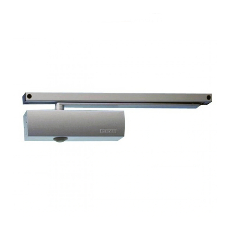
The ECturn is a swing door drive operating fully automatically that is actuated by sensors or switches.
The ECturn operates electrically during opening and closing.
ECturn eld of application
Light grey Low energy Dark grey Automatic
Mechanical data
Dimensions (H x D x L): 60 mm x 60 mm x 580 mmà
Ambient temperature range: –15 °C to +50 °Cà
Drive mass: approx. 3 kgà
Electrical data
Mains connection: 110–230 V AC +10% –14%, 50/60 Hzà
Power consumption: max. 75 Wà
Externally connectable devices: 24 V DC, max. 600 mAà

ECturn
6
Product description
Basic structure and extension6.2
Drive6.2.1
Controller cover1
Motor2
Gearing3
Battery (optional)4
Power connection (in the side element)5
Power plug6
Spindle cover7
Controller with power pack8
Hood (optional)9
Height-adjustable guide rail (±2 mm)6.2.2
Slide block10
Rail11
End piece12
Lever13

ECturn
7
Product description
Link arm6.2.3
For sot depth SD:
0 … 100 mmà
90 … 200 mmà
Mounting plate for drives (optional)6.2.4
Depending on the installation situation a mounting plate is required. A mounting plate is generally recommend-
ed to facilitate mounting.
Actuation elements (accessories)6.2.5
In accordance with the specications in the wiring diagram, Mat. No. 134079

ECturn
8
Types of mounting, stops
Types of mounting, stops7
The opening angle of the door has to be limited by a door stop.
Accessories: Door stop buer, integrated opening restrictor (only for guide rail).
The ECturn allows the following types of stop, each for doors DIN left and doors DIN right:
Hinge side Opposite hinge side
Transom mounting hinge side
with guide rail
max. sot depth SD: 40 mm
max. door overlap O: 40 mm
Transom mounting opposite hinge side
with link arm for
sot depths SD: 0…100 mm
90…200 mm
Door panel mounting hinge side
with guide rail
max. door overlap O: –50…+30 mm
Transom mounting opposite hinge side
with guide rail
max. sot depth SD: 30 mm
Door panel mounting hinge side
with link arm
max. door overlap O: 200 mm
Door panel mounting opposite hinge side
with guide rail
max. sot depth SD: 20 mm
O Door overlap SD Sot depth

ECturn
9
Mounting
Mounting8
General information for mounting8.1
Observe all the instructions. Incorrect mounting can result in serious injuries.à
Observe the specied ambient temperature range at the installation location of the drive.à
After completing mounting check the settings and functionality of the drive!à
Scope of delivery and completeness8.1.1
Open all the packaging units. Check whether they are complete and familiarise yourself with the parts.
X
ECturn door drive with guide rail or link arm
Drive unità
1 driveà
1 set of fastening screwsà
Depending on order:
Slide railà
1 railà
1 leverà
1 set of fastening screwsà
or
Link arm (size depending on sot depth)à
1 set of fastening screwsà
Accessories (optional)à
Hoodà
Actuation elements: in accordance with the specications in the wiring diagramà
Door stop buerà
Mounting plate(s) with a set of fastening screwsà
Batteryà
Radio circuit board DCU702à
Door transmission cableà
Preparations to be made by the customer8.1.2
Checking of the location conditions and the required physical conditions
WARNING!
Danger of injury through falling components!
Unsecured components may fall down when under load.
When mounting the ECturn swing door drive ensure that the substructure ensures safe fastening of the drive.
X
Use suitable means of fastening such as anchors, rivet nuts, etc.
X
Before mounting the drive check whether the door leaf is in a good mechanical state and can be opened and
X
closed easily.
Mount the bottom edge of the element mounted at the lowest point (guide rail or link arm) at least 2 m above
X
the oor.
Lay cables in accordance with the cable plan.
X
Check the planned type of stop on the leaf or frame prole (see Chapter 7).
X

ECturn
10
Mounting
Mounting dimensions for the types of mounting8.2
Transom mounting hinge side with guide rail8.2.1
Fixing with mounting plate Direct xing
Dimensional reference hinge middle14
Cable entry for power supply cable15
Cable entry for control cables16
Observe drilling template: DIN left and DIN right mirrored.
X
Fastening means
Mounting plate M5à
Base plate M5 or chip board screwsà
Guide rail M5 or chip board screwsà
Take drive orientation into account: Motor towards hinge.
X
Required space
ECturn required space17
Dimensional reference top edge door prole = Top18
edge guide rail
Required space for guide rail19

ECturn
11
Mounting
Transom mounting opposite hinge side with guide rail8.2.2
Fixing with mounting plate Direct xing
575
415
390.5
302
142
78
Ø16
70
498.5
Ø16
16
14
15
633
390.5
266
131
78
70
498.5
Ø16
16
15
14
14 Dimensional reference hinge middle
15 Cable entry for power supply cable
16 Cable entry for control cables
Observe drilling template: DIN left and DIN right mirrored.
X
Fastening means
Mounting plate M5à
Base plate M5 or chip board screwsà
Guide rail M5 or chip board screwsà
Take drive orientation into account: Motor towards hinge.
X
Required space
17 ECturn required space
19 Required space for guide rail
20 Dimensional reference bottom edge frame (lintel)

ECturn
12
Mounting
Transom mounting opposite hinge side with link arm8.2.3
Fixing with mounting plate Direct xing
14 Dimensional reference hinge middle
15 Cable entry for power supply cable
16 Cable entry for control cables
21 For mounting dimensions of the link arm refer to the "ECturn link arm mounting instructions" (134590)
Observe drilling template: DIN left and DIN right mirrored.
X
Fastening means
Mounting plate M5à
Base plate M5 or chip board screwsà
Take drive orientation into account: Motor towards hinge.
X
Required space
17 ECturn required space
20 Dimensional reference bottom edge frame
(lintel)
22 Space required link arm

ECturn
13
Mounting
Door panel mounting hinge side with link arm8.2.4
Fixing with mounting plate Direct xing
14 Dimensional reference hinge middle
15 Cable entry for power supply cable
16 Cable entry for control cables
21 For mounting dimensions of the link arm refer to the "ECturn link arm mounting instructions" (134590)
Observe drilling template: DIN left and DIN right mirrored.
X
Fastening means
Mounting plate M5à
Base plate M5 or chip board screwsà
Take drive orientation into account: Motor towards hinge.
X
Required space
17 ECturn required space
18 Dimensional reference top edge door prole
22 Space required link arm

ECturn
14
Mounting
Door panel mounting hinge side with guide rail8.2.5
Fixing with mounting plate Direct xing
14 Dimensional reference hinge middle
15 Cable entry for power supply cable
16 Cable entry for control cables
Observe drilling template: DIN left and DIN right mirrored.
X
Fastening means
Mounting plate M5à
Base plate M5 or chip board screwsà
Guide rail M5 or chip board screwsà
Take drive orientation into account: Motor towards hinge.
X
Required space
17 ECturn required space
18 Dimensional reference top edge door prole
19 Required space for guide rail

ECturn
15
Mounting
Door panel mounting opposite hinge side with guide rail8.2.6
Fixing with mounting plate Direct xing
14 Dimensional reference hinge middle
15 Cable entry for power supply cable
16 Cable entry for control cables
Observe drilling template: DIN left and DIN right mirrored.
X
Fastening means
Mounting plate M5à
Base plate M5 or chip board screwsà
Guide rail M5 or chip board screwsà
Take drive orientation into account: Motor towards hinge.
X
Required space
17 ECturn required space
19 Required space for guide rail
20 Dimensional reference bottom edge frame
(lintel)

ECturn
16
Mounting
Mounting the drive8.3
During mounting ensure that the connection cables are not pinched.
X
Pull the hood o.
X
If necessary, screw on the mounting plate.
X
Screw on the drive.
X
For positioning refer to the top view in the drawings of Chapter 8.2.
Break out the plastic part in the hood for the spindle.
X
Mount the spindle cover.
X
Fill in the information plate and stick it clearly visible onto the drive unit.
X
Attach the hood.
X
Use the supplied M5 screws or chip board screws.
X
Mounting the guide rail8.4
Mounting the lever8.4.1
In order to mount the lever use only the supplied hexagon socket-head screw with coating in the lower thread
X
section!
Mounting the guide rail8.4.2
Observe the mounting instructions for the guide rail.
X
The slide block can be clipped out of the lever for dismantling.
Transom mounting guide rail
Door panel mounting guide rail
Screw in the hexagon socket-head screw (23) and tighten it (tightening torque 15 Nm).
X
Mounting the link arm8.5
Observe the mounting instructions in the link arm packaging.
X

ECturn
17
Mounting
Door stop limiting8.6
When mounting the door panel take care of the pinch and shearing points of the door edges when laying the
X
cables!
Use the guide rail only with and integrated buer or use a stop buer on the oor.
X
Use the link arm only with a stop buer on the oor.
X
Check the physical conditions.
X
Open and close the door manually.
X
Mount the stop buer (24) on the oor.
X
Mounting and connecting the battery8.7
Screw on the battery (4) using 2 screws (25).
X
Plug the plug (26) into the slot.
X

ECturn
18
Mounting
Mounting the door transmission cable (optional)8.8
Loosen bolts (27).
X
Remove the cover (28) for the side element.
X
Break out the breaking point (29) in the cover (28).
X
Unscrew the nut (31) at the door transmission cable (30).
X
Thread the door transmission cable (30) through the cover (28).
X
Screw the nut (31) tight in the cover (28).
X
Loosen the strain relief (33).
X
Loosen the screw (34) and pull o the protective conductor.
X
Loosen the cable at the terminal strip (35).
X
Remove the power plug (32) with cable.
X

ECturn
19
Electrical connection
Connect the door transmission cable in the terminal strip (35) in accordance with the wiring diagram.
X
Connect the protective conductor and secure with screw (34).
X
Place on the cover (28) for the side element.
X
Tighten screws (27).
X
Mounting the hood (optional)8.9
During mounting ensure that cables are not pinched.
X
Slide the hood (36) over the ECturn until it latches in audibly. Take the position of the drive axle of the motor-
X
gearing unit into account.
Mounting the actuation sensors8.10
Sensors mounted on the wall or ceiling have to be positioned so that the door does not move through the eld
of detection of the sensor during opening and closing since self-actuation is otherwise possible.
For electrical connections, see the wiring diagram.
Mounting the radio circuit board (optional)8 .11
Observe the mounting instructions in the packaging of the radio circuit board DCU702.
X
Electrical connection9
Mains connection9.1
The ECturn swing door drive is provided with a power plug in the factory. If there are cables provided by the
customer and connection is not carried out with the power plug, the power connection has to be carried out by a
qualied electrician.
WARNING!
Danger of fatal injury through electric shock when connecting the ECturn swing door drive without a power
plug.
The electrical system (230 V) may only be connected by a qualied electrician!
X
Observe the VDE regulations.
Use suitable means of fastening such as anchors, rivet nuts, etc.
X

ECturn
20
Electrical connection
When mounting the door panel take care of the pinch and shearing points of the door edges when laying the
X
cables!
Before working on the electrical system, disconnect the system from the mains network.
X
If it exists, unplug the battery.
X
In accordance with the valid regulations it must be possible to deenergize the door drive at a suitable point.à
In the case of a xed connection by the customer, provide an all-pole disconnecting device.
X
If exible cables are used, always use insulated wire-end ferrules.
X
Plug in the power plug (32).
X
If there are cables provided by the customer and connection is not carried out with the power plug:
Loosen bolts (27).
X
Remove the cover (28) for the side element.
X
Loosen the strain relief (33).
X
Loosen the screw (34) and pull o the protective conductor.
X
Loosen the cable at the terminal strip (35).
X
Remove the power plug (32) with cable.
X
Connect the 230 V power cable in the terminal strip (35) in accordance with the wiring diagram.
X
Connect the protective conductor and secure with screw (34).
X
The sheath of the power supply cable must be laid to the strain relief (33).
Tighten the strain relief (33).
X
Place on the cover (28) for the side element.
X
Tighten screws (27).
X
Other manuals for ECturn
4
Table of contents
Other GEZE Door Opening System manuals

GEZE
GEZE TSA 160 NT User manual

GEZE
GEZE TS 5000 R-ISM BG User manual

GEZE
GEZE TS 5000 User instructions

GEZE
GEZE GC 342+ User manual

GEZE
GEZE MSW sliding wall system Service manual

GEZE
GEZE Slimdrive SL NT User manual

GEZE
GEZE TS 5000 R User manual

GEZE
GEZE TS 5000 User instructions

GEZE
GEZE E-ISM User manual

GEZE
GEZE Slimdrive SD User manual

GEZE
GEZE TS 3000B User manual

GEZE
GEZE Levolan 60 User manual

GEZE
GEZE Powerturn Series Quick guide

GEZE
GEZE GC 307+ User manual

GEZE
GEZE ECdrive H User manual

GEZE
GEZE Slimdrive SLT Quick guide

GEZE
GEZE TS 5000 L-E-ISM VPK User manual

GEZE
GEZE ECdrive H Guide

GEZE
GEZE Slimdrive EMD-R User manual

GEZE
GEZE TS 5000 E BG User manual