GEZE ISM Boxer User manual

GEZE
ISM Boxer
DE Boxer Gleitschiene mit integrierter
Schließfolgeregelung
GB Boxer guide rail with integrated
closing sequence control
FR Boxer bras à coulisse avec régulation
intégrée de fermeture en cascade
153316-01
DE Montageanleitung
GB Installation instructions
FR Instruction de montage

ISM Boxer
DE 2
Zu diesem Dokument
1 Zu diesem Dokument
Diese Anleitung beschreibt die Montage und den Anschluss sowie die Inbetriebnahme der GEZE Boxer ISM Gleit-
schiene. Verwendung mit:
àGeze Boxer Gr. 2-4
àGeze Boxer Gr. 3-6
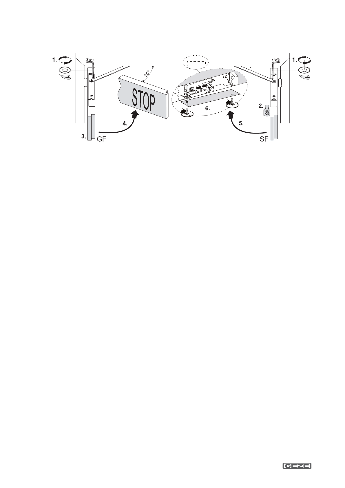
ISM Boxer: Türönungwinkel ca. 120°.
Variante kleiner Bandabstand (1130-1300 mm): Türönungswinkel: ca. 100°.
Variante kleiner Standügel (min. Standügelbreite 420 mm zuzüglich Platzbedarf für Verriegelung):
Türönungswinkel Gangügel ca. 120°, Türönungswinkel Standügel ca. 100°.
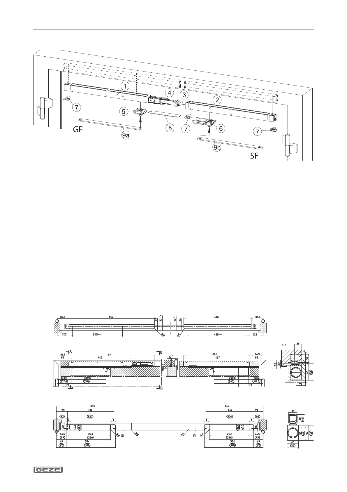
1.1 Produktbeschreibung
Diese Gleitschiene ist für die Montage an zweiügeligen Feuer- und Rauchschutztüren zugelassen. Die Anlage
enthält eine integrierte Schließfolgeregelung. Wird bei geöneten Türügeln der Gangügel geschlossen, bleibt
der Gangügel in seiner Warteposition, bis der Standügel geschlossen ist und über die Schließfolgeregelung den
Gangügel freigibt.
Wenn der Standügel einer zweiügeligen Tür mit Brand- und/oder Rauchschutzeigenschaften geönet werden
kann, ohne dass der Gangügel in die Mindestwarteposition gelangt, ist eine möglichst einstellbare Mitnehmerklap-
pe wie die GEZE Mitnehmerklappe CBex einzusetzen um die Funktion der Schließfolgeregelung sicherzustellen.
1.2 Weitere Dokumente
Im Lieferumfang der Komponenten sind jeweils weitere Unterlagen zur Montage bzw. zum Anschluss der Anlage
enthalten. Bitte diese zu beachten.
Montage der Schließer, siehe Montageanleitung Boxer.
2 Symbole und Darstellungsmittel
Warnhinweise
In dieser Anleitung werden Warnhinweise verwendet, um Sie vor Sach- und Personenschäden zu warnen.
XLesen und beachten Sie diese Warnhinweise immer.
XBefolgen Sie alle Maßnahmen, die mit dem Warnsymbol und Warnwort gekennzeichnet sind.
Warnsymbol Warnwort Bedeutung
GEFAHR Gefahren für Personen.
Nichtbeachtung führt zu Tod oder schweren Verletzungen.
– VORSICHT Informationen zur Vermeidung von Sachschäden, zum Verständnis oder zum Optimie-
ren der Arbeitsabläufe.
Weitere Symbole und Darstellungsmittel
Um die korrekte Bedienung zu verdeutlichen, sind wichtige Informationen und technische Hinweise besonders
herausgestellt.
Symbol Bedeutung
bedeutet „Wichtiger Hinweis“
bedeutet „Zusätzliche Information“
XSymbol für eine Handlung: Hier müssen Sie etwas tun.
XHalten Sie bei mehreren Handlungsschritten die Reihenfolge ein.
3 Produkthaftung
Gemäß der im Produkthaftungsgesetz denierten Haftung des Herstellers für seine Produkte sind die in dieser
Broschüre enthaltenen Informationen zu beachten. Die Nichtbeachtung entbindet den Hersteller von seiner
Haftungspicht.
4 Sicherheitshinweise
àMontage, Inbetriebnahme und Reparaturen sind durch einen Fachbetrieb auszuführen.
àNur GEZE Originalteile für Reparaturarbeiten verwenden.
àEigenmächtige Veränderungen an der Anlage schließen eine Haftung von GEZE für daraus resultierende Schäden aus.
àBei Anwendung an Feuer- und Rauchschutzabschlüssen sind die länderspezischen Vorschriften zu beachten.
àMax. Türönungswinkel mit Türstopper begrenzen.

ISM Boxer
DE 3
Lieferumfang
5 Lieferumfang
Abb.: 5.1.1
GF Gangügel
SF Standügel
1 ISM Boxer Gleitschiene GF
2 ISM Boxer Gleitschiene SF
3 Drahtseil für Auslöser
4 Auslöser
5 Gleitstein
Gangügel
6 Gleitstein
Standügel
7 Endkappen
8 Blende
Schrauben und Zubehörbeutel
(ohne Abbildung)
ISM Boxer Standard
(siehe Kap. 6.1.1)
9a Gleithebel GF (L = 317 mm)
9b Gleithebel SF (L = 317 mm)
ISM Boxer kleiner Bandabstand
(siehe Kap. 6.1.2)
9a Gleithebel GF (L = 240 mm)
9b Gleithebel SF (L = 240 mm)
ISM Boxer kleiner Standügel
(siehe Kap. 6.1.3)
9a Gleithebel GF (L = 317 mm)
9b Gleithebel SF (L = 240 mm)
6 Montage, Befestigung
XTür gemäß Kap. 6.1 vorbereiten.
XBoxer und Gleithebel nach Anleitung montieren und das Schließzeitventil schließen.
Auf Anfrage stellt GEZE für die gängigen Türprole Einbauzeichnungen zur Verfügung.
6.1 Montagevorbereitung
6.1.1 ISM Boxer Standard
Rahmenbearbeitung
Türügelbearbeitung GEZE Boxer Gr. 3-6/Gr. 2-4
Rahmen- und Türügelbearbeitung für Rechtsügel spiegelbildlich. Maße in für GEZE Boxer Gr. 2-4
Abb.: 6.1.1.1

ISM Boxer
DE 4
Montage, Befestigung
6.1.2 Variante kleiner Bandabstand
Rahmenbearbeitung
595.5
Türügelbearbeitung GEZE Boxer Gr. 3-6/Gr. 2-4
8 8
Rahmen- und Türügelbearbeitung für Rechtsügel spiegelbildlich. Maße in für GEZE Boxer Gr. 2-4
Abb.: 6.1.2.1
6.1.3 Variante kleiner Standügel
Rahmenbearbeitung
Türügelbearbeitung GEZE Boxer Gr. 3-6/Gr. 2-4
Rahmen- und Türügelbearbeitung für Rechtsügel spiegelbildlich. Maße in für GEZE Boxer Gr. 2-4
Abb.: 6.1.3.1

ISM Boxer
DE 5
Montage, Befestigung
6.2 Standügel Gleitschiene montieren
Abb.: 6.2.1
XGleitstein richtungsorientiert in Standügel-Gleitschiene einführen (1.).
XStandügel-Gleitschiene mit 2 Schrauben befestigen (2.) (Anzugsmoment: 2 Nm).
XEndkappe auf Gleitschiene aufklipsen (3.).
XDrahtseil (Kugel zum Gangügel) durch die Kammer zur Ausfräsung Gangügel-Gleitschiene durchführen (4.)
Alle Schraubmomente sind ggf. bauseitig anzupassen.
6.3 Gangügel Gleitschiene montieren
Abb.: 6.3.1
XGleitstein richtungsorientiert in Gangügel-Gleitschiene einführen (1.).
XDrahtseil in den Auslösehebel einhängen (2.).
XGangügel-Gleitschiene mit 2 Schrauben befestigen (3.) (Anzugsmoment: 2 Nm).
XEndkappe auf Gleitschiene aufklipsen (4.).
Alle Schraubmomente sind ggf. bauseitig anzupassen.

ISM Boxer
DE 6
Montage, Befestigung
6.4 Auslöser positionieren
2,5
Abb.: 6.4.1
XBefestigungsschrauben des Auslösers ca. 1/2 Umdrehung lösen (1.).
XGleithebel mit Standügelgleitstein verbinden (2.) (Anzugsmoment: 5 Nm).
XSchließzeitventil „1“ am Boxer Standügel önen (3.).
XStandügel schließen (Auslöser wird positioniert) (4.).
VORSICHT
Beim Schließen darauf achten, dass das Drahtseil nicht in den Türspalt eingeklemmt wird.
XStandügel wieder önen (5.).
XStandügel oen halten (6.).
XBefestigungsschrauben des Auslösers anziehen (7.) (Anzugsmoment: 0,4 Nm).
6.5 Drahtseil mit Auslöser verbinden
XDrahtseil in Trichter einführen und an der Umlenkrolle herausziehen (1.).
XAuslöseschieber einrasten (2.).
XKlemmschraube lösen (3.).
XDrahtseil durch das Klemmteil schieben (4.).
XDrahtseil straen (5.).
XKlemmschraube festziehen (6.).
XÜberstehendes Drahtseil auf 50 mm kürzen (7.).
XEndkappe auf Standügelgleitschiene aufklipsen (8.).
Abb.: 6.5.1

ISM Boxer
DE 7
Montage, Befestigung
6.6 Auslöser und Sperre einstellen
XAchten Sie darauf, dass das Drahtseil nicht eingeklemmt wird.
Bei korrekter Einstellung müssen die Scheibe und die Kerbe in einer Flucht liegen.
XKontrollieren, ob der Auslöseschieber noch eingerastet ist. Der Spalt zwischen Sicherungsscheibe und
Markierung sollte 1–5 mm betragen (1.) (siehe Bild A).
XDrahtseil an der Stellschraube so einstellen, dass sich die Sicherungsscheibe mit der Kerbe deckt (2.) (siehe
Bild B).
Abb.: 6.6.1
6.7 Funktionssicherung der Schließfolgeregelung positionieren
Abb.: 6.7.1
XStandügel schließen (1.).
XGleithebel mit Gangügelgleiter verbinden (2.) (Anzugsmoment: 5 Nm).
XMitnehmer maximal herausziehen (3.).
XSchrauben der Funktionssicherung lösen, max. 1/2 Umdrehung (4.).
XAnschlagstange herausziehen (5.).
àAbstand Kante-Sperre und Anschlag: ca. 30 mm
XSchließzeitventil „1“ am Gangügel önen (6.).
XGangügel schließen (7.).
Anschlagstange für Funktionssicherung der Schließfolgeregelung ist positioniert.
XGangügel önen (8.).
XSchrauben der Anschlagstange festziehen (9.).
VORSICHT
Anschlagstange darf nicht unter den Mitnehmer kippen.

ISM Boxer
DE 8
Wartung, Pege, Reparatur
6.8 Funktionstest der Schließfolgeregelung
Abb.: 6.8.1
XSchließzeit an Stand- und Gangügel einstellen (1.).
Empfehlung:
àGangügel Schließzeit 5 Sekunden (aus 90°).
àStandügel Schließzeit 5 Sekunden (aus 90°).
XStandügel 90° Türönungswinkel önen und festsetzen (2.).
XGangügel 90° Türönungswinkel önen (3.).
XGangügel schließen lassen (4.).
Bei einem Türönungswinkel von >35° muss der Türügel stehen bleiben.
XStandügel schließen (5.). Sperre wird ausgelöst und der Gangügel läuft zu.
XBlende anschrauben (6).
7 Wartung, Pege, Reparatur
Die Einbaurma muss den Betreiber der Anlage auf diesen Teil der Montageanleitung aufmerksam machen, und
diese sowie die Benutzerinformation (Beipackzettel zum Türschließer) dem Betreiber aushändigen.
Eine regelmäßige Wartung muss durchgeführt werden (siehe „GEZE-Benutzerinformation Türschließer“). Sie ist
von einem Fachbetrieb auszuführen. Eventuelle Reparaturen müssen von GEZE oder durch von GEZE autorisier-
tes Fachpersonal ausgeführt werden.

ISM Boxer About this document
1 About this document
These instructions describe the installation and commissioning of the GEZE Boxer ISM guide rail.
In conjunction with:
àGeze Boxer size 2-4
àGeze Boxer size 3-6
ISM Boxer: Opening angle of doors approx. 120°.
Version small hinge distance (1130-1300 mm): Opening angle of doors: approx. 100°.
Version small xed leaf (min. leaf width 420 mm plus space requirement of the locking system):
Opening angle of doors: moving leaf approx. 120° / xed leaf approx. 100°.
1.1 Product description
This slide rail is approved for installation on double-leaf re and smoke protection doors. The system contains an
integrated closing sequence control. If the moving leaf is closed with the door leaves opened, the moving leaf
remains in its waiting position until the xed leaf is closed and releases the moving leaf via the closing sequence
control.
If a double leaf smoke or re protection door can be opened via the passive leaf, without opening the active leaf
up to the minimal waiting position of the sequence control, a preferably adjustable carry bar such as the GEZE
CBex must be used to ensure the functionality of the door sequence control unit.
1.2 Related documents
Additional documents for the installation and connection of the system are supplied with every component.
Please follow these instructions.
For mounting of the door closer, refer to the Boxer mounting instructions.
2 Key to symbols
Warning
In these instructions, warnings are used to warn against material damage and injuries.
XAlways read and observe these warnings.
XFollow all instructions marked with the warning symbol and the word WARNING.
Warning
symbol
Warning Meaning
DANGER Danger for people.
Non-observance can result in death or serious injuries.
– CAUTION Information to prevent damage to property and to understand and optimise workow.
Further symbols used in these instructions
Important information and technical notes are emphasised to illustrate the correct operation.
Symbol Meaning
means “Important note“
means “Additional information”
XSymbol for a user action. Here you have to take an action.
XObserve the sequence if there are several action steps.
3 Product liability
According to the denition of manufacturer‘s liability for his products in the Product Liability Act, the informati-
on contained in this brochure are to be followed. Ignoring this information absolves the manufacturer from his
liability.
4 Safety instructions
àInstallation, commissioning and repairs must be performed by a specialist.
àUse only GEZE original parts for repair work.
àUnauthorised modications of the system excludes GEZE from the liability for any resulting damage.
àWhen used in re and smoke barriers, all local regulations should be observed.
àRestrict the opening angle of the doors by a door stopper.
GB 2

ISM Boxer
Scope of delivery
5 Scope of delivery
Fig.: 5.1.1
GF Moving leaf
SF Fixed leaf
1 ISM Boxer GF guide rail
2 ISM Boxer SF guide rail
3 Wire cable for trigger
4 Trigger
5 Sliding block
GF
6 Sliding block
SF
7 End caps
8 Cover panel
Screws and accessories bag
(without illustration)
ISM Boxer standard
(see Chapter 6.1.1)
9a Sliding lever GF (L = 317 mm)
9b Sliding lever SF (L = 317 mm)
ISM Boxer small hinge distance
(see Chapter 6.1.2)
9a
Sliding lever GF (L = 240 mm)
9b Sliding lever SF (L = 240 mm)
ISM Boxer small xed leaf
(see Chapter 6.1.3)
9a Sliding lever GF (L = 317 mm)
9b Sliding lever SF (L = 240 mm)
6 Mounting and securing
XPrepare the door as shown in chapter 6.1.
XFit the Boxer and sliding lever and close the closing time valve.
On request, GEZE will provide installation drawings for most common door proles.
6.1 Drilling template
6.1.1 ISM Boxer
Work on doorframe
Work on leaf GEZE Boxer size 3-6/size 2-4
Work on frame and leaf for right leaf, mirror image Dimensions in for GEZE Boxer size 2-4 Fig.: 6.1.1.1
GB 3

ISM Boxer Mounting and securing
6.1.2 Version small hinge distance
Work on doorframe
595.5
Work on leaf GEZE Boxer size 3-6/size 2-4
8 8
Work on frame and leaf for right leaf, mirror image Dimensions in for GEZE Boxer size 2-4
Fig.: 6.1.2.1
6.1.3 Version small xed leaf
Work on doorframe
Work on leaf GEZE Boxer size 3-6/size 2-4
Work on frame and leaf for right leaf, mirror image Dimensions in for GEZE Boxer size 2-4
Fig.: 6.1.3.1
GB 4

ISM Boxer
Mounting and securing
6.2 Mounting xed leaf guide rail
Fig.: 6.2.1
XInsert the sliding pad into the guide rail for the xed leaf, making sure it faces the right way
(1.).
XFasten guide rail for xed leaf with 2 screws (2.) (tightening torque: 2 Nm).
XClip the end cap onto the guide rail (3.).
XThread the steel wire (ball to the moving) leaf through the chamber to the recess in the guide rail of the mo-
ving leaf (4.).
All screwing torques are to be adjusted on site, if necessary.
6.3 Mounting moving leaf guide rail
Fig.: 6.3.1
XInsert the sliding pad into the guide rail for the moving leaf, making sure it faces the right way
(1.).
XAttach the steel wire to the release lever (2.).
XFasten guide rail for moving leaf with 2 screws (3.) (tightening torque: 2 Nm).
XClip the end cap onto the guide rail (4.).
All screwing torques are to be adjusted on site, if necessary.
GB 5

ISM Boxer Mounting and securing
6.4 Positioning the trigger unit
2,5
Fig.: 6.4.1
XRelease the xing screws of the release trigger by about 1/2 turn (1.).
XConnect the sliding lever with the sliding pad of the xed leaf (2.) (tightening torque: 5 Nm).
XOpen the closing time valve„1“ at the Boxer xed leaf (3.).
XClose the xed leaf (release trigger will be positioned) (4.).
CAUTION
When closing, make sure that the steel wire does not get wedged in the gap
XRe-open the xed leaf (5.).
XKeep the xed leaf open (6.).
XInsert the xing screws of the release trigger and tighten (7.) (tightening torque: 0,4 Nm).
6.5 Connect the steel wire to the release trigger
XThread the steel wire into the funnel and pull it out at the deection pulley (1.).
XEngage the release slide (2.).
XRelease the clamping screw (3.).
XPush the steel wire through the clamping device (4.).
XTighten the steel wire (5.).
XLightly tighten the clamping screw (6.).
XCut back the steel wire to a length of about 50 mm (7.).
XClip the end cap onto the guide rail of the secondary leaf (8.).
Fig.: 6.5.1
GB 6

ISM Boxer
Mounting and securing
6.6 Adjust trigger and lock
XEnsure that the wire cable is not pinched.
When adjusted correctly, the disc and the notch must be aligned.
XCheck that the release slide is still engaged. The gap between retaining disk and the mark should be 1–5 mm.
(1.) (see gure A).
XCheck that the release slide is still engaged. The gap between retaining disk and the mark should be 1–5 mm
(2.) (see gure B).
Fig.: 6.6.1
6.7 Positioning the function saveguard of the integrated closing sequence control
Fig.: 6.7.1
XClose the xed leaf (1.).
XConnect the sliding lever with the sliding pad of the moving leaf. (2.) (tightening torque: 5 Nm).
XPull out the driver (3.).
XRelease the screws of the tamper-proong device, max. 1/2 turn (4.).
XPull out the stop bar (5.).
àDistance edge of lock and stop bar approx. 30 mm.
XOpen the closing time valve„1“ at the moving leaf (6.).
XClose the moving leaf (7.).
The stop bar for the tamper-proong device has been positioned.
XOpen the moving leaf (8.).
XTighten the screws of the tamper-proong device (9.).
CAUTION
Stop bar must not be pass under the driver.
GB 7

ISM Boxer Maintenance, servicing, repairs
6.8 Functional test - Closing sequence control
Fig .: 6.8.1
XSet the closing time for the secondary and the moving leaf (1.).
Recommended:
àClosing time for moving leaf 5 seconds (from 90°).
àClosing time for xed leaf 5 seconds (from 90°).
XOpen xed leaf by 90° and hold xed (2.).
XOpen the moving leaf by 90° (3.).
XLet the moving leaf close (4.).
The door should stop at an opening angle of >35°.
XNow close the xed leaf (5.). The lock is released and the moving leaf closes.
XFit the cover panel (6).
7 Maintenance, servicing, repairs
The installing company must alert the operator of the system to this part of the mounting instructions and hand
it over to the operator together with the user information (instruction leaet for door closer).
Regular servicing has to be carried out (see “GEZE user information for door closer”). It is to be carried out by a
qualied specialist company.
Any repairs are to be carried out by GEZE or qualied personnel authorised by GEZE.
GB 8

ISM Boxer
FR 2
Concernant le présent document
1 Concernant le présent document
Le présent manuel décrit le montage et la mise en service ainsi que le raccordement du bras à coulisse GEZE Boxer ISM.
Utilisation avec:
àGeze Boxer taille 2-4
àGeze Boxer taille 3-6
ISM Boxer: Angle d’ouverture 120° max.
Variante petite distance entre les paumelles (1130 -1300 mm)
: Angle d’ouverture : 100° max.
Variante petit battant xe (min. vantail large 420 mm plus l‘espace nécessaire pour le système de verrouillage): Angle
d’ouverture battant mobile 120° max. / battant xe 100° max
1.1 Description du produit
L’installation comprend une régulation de fermeture en cascade. Lorsqu’on ferme le battant mobile alors que les deux
battants sont ouverts, le battant mobile reste dans sa position d’attente jusqu’à ce que le battant xe soit aussi fermé
et que la régulation de fermeture en cascade libère le battant mobile.
Si une porte à deux vantaux coupe-feu et/ou pare-fumée peut être ouverte par le vantail xe, sans ouvrir le van-
tail de service au moins jusqu’à la position d’attente, un dispositif anti-chevauchement ajustable doit être utilisé,
comme le dispositif GEZE CBex, an d’assurer le bon fonctionnement du contrôle de la fermeture.
1.2 Autres documents
L‘emballage contenant les composants comporte d‘autres documents pour le montage ou le branchement de
l‘installation. Il convient de les respecter. Pour montage du ferme porte, voir le
manuel Boxer
.
2 Symboles et moyens de représentation
Mises en garde
Ce manuel contient des mises en garde pour vous protéger des dommages personnels et matériels.
XLisez et observez toujours ces mises en garde.
XObservez toutes les mesures identiées par le symbole et le mot de mise en garde.
Symbole de
mise en garde
Mot de mise
en garde
Signication
DANGER Dangers pour les personnes.
Le non respect peut entraîner la mort ou des blessures graves.
– ATTENTION Informations destinées à éviter les dommages matériels, à une meilleure compréhensi-
on ou à l‘optimisation des processus de travail.
Autres symboles et moyens de représentation
Pour illustrer l‘utilisation correcte, les informations et consignes techniques importantes sont présentées de sorte à
attirer l‘attention.
Symbole Signication
signie « Remarque importante »
signie « Information complémentaire »
XSymbole pour une action : ici vous êtes invité à exécuter une action.
XLors de plusieurs étapes d‘action, respectez l‘ordre prescrit.
3 Responsabilité du produit
Conformément à la responsabilité du fabricant pour ses produits dénie dans la loi sur la responsabilité civile des pro-
duits, les informations contenues dans la présente brochure doivent être respectées. Le non-respect délie le fabricant
de son obligation de responsabilité.
4 Consignes de sécurité
àLe montage, la mise en service et les réparations doivent être eectués par une entreprise spécialisée.
àUtiliser uniquement des pièces GEZE d‘origine pour les travaux de réparation.
àToute modication du propre chef eectuée sur l‘installation exclut la responsabilité de GEZE pour les dommages en
résultant.
àIl convient de respecter les dispositions nationales en vigueur en cas d‘utilisation sur des portes anti-feu et anti-fumée
àLimiter l‘angle d‘ouverture en utilisant le stop-porte.

ISM Boxer
FR 3
Contenu de la livraison
5 Contenu de la livraison
Fig.: 5.1.1
GF Battant mobile
SF Battant xe
1 ISM Bras à coulisse du GF
2 ISM Bras à coulisse du SF
3 Câble pour dispositif de
déclenchement
4 Dispositif de déclenchement
5 Coulisseau GF
6 Coulisseau SF
7 Capuchons
8 Cache
Vis de xation et sachet
d‘accessoires (sans illustration)
ISM Boxer standard
(voir chapitre 6.1.1)
9a Levier coulissant GF (L = 317 mm)
9b Levier coulissant SF (L = 317 mm)
ISM Boxer petite distance entre
les paumelles (voir chapitre 6.1.2)
9a Levier coulissant GF (L = 240 mm)
9b Levier coulissant SF (L = 240 mm)
ISM Boxer petit battant xe
(voir chapitre 6.1.3)
9a Levier coulissant GF (L = 317 mm)
9b Levier coulissant SF (L = 240 mm)
6 Montage, xation
XPréparer le bloc porte conformément au chapitre. 6.1.
XMonter le ferme-porte boxer et le levier coulisseau et fermer la vanne de temps de fermeture.
GEZE met à disposition sur simple demande les plans et notices de montage pour les prols de vantaux usuels.
6.1 Gabarit de perçage
6.1.1 ISM Boxer standard
Traitement de cadre
Traitement de battant de porte GEZE Boxer taille 3-6/taille 2-4
Traitement de cadre et battant de porte pour battant mobile, gauche rééchi Dimensions
en pour GEZE Boxer Gr. 2-4 Fig.: 6.1.1.1

ISM Boxer
FR 4
Montage, xation
6.1.2 Variante petite distance entre les paumelles
Traitement de cadre
595.5
Traitement de battant de porte GEZE Boxer taille 3-6/taille 2-4
8 8
Traitement de cadre et battant de porte pour battant mobile, gauche rééchi Dimensions
en pour GEZE Boxer Gr. 2-4 Fig.: 6.1.2.1
6.1.3 Variante petit battant xe
Traitement de cadre
Traitement de battant de porte GEZE Boxer taille 3-6/taille 2-4
Traitement de cadre et battant de porte pour battant mobile, gauche rééchi Dimensions
en pour GEZE Boxer Gr. 2-4 Fig.: 6.1.3.1

ISM Boxer
FR 5
Montage, xation
6.2 Glissière battant xe
Fig.: 6.2.1
XIntroduire le coulisseau en respectant la bonne orientation de celui-ci dans la glissière du battant xe (1.).
XFixer la glissière du battant xe avec 2 vis (2.) (couple de serrage: 2 Nm).
XClipper le capuchon-câche en bout de glissière côté paumelles (3.).
XPasser le câble métallique de sélection (l’embout de câble vers le battant mobile) dans les usinages de dor-
mant prévus à cet eet (4.).
Tous les couples de serrage doivent être adaptés sur site.
6.3 Glissière battant mobile xe
Fig.: 6.3.1
XIntroduire le coulisseau en respectant la bonne orientation de celui-ci dans la glissière du battant mobile
(1.).
XPasser le câble de sélection mécanique dans le levier de déclenchement (2.).
XFixer la glissière du battant xe avec 2 vis (3.) (couple de serrage: 2 Nm).
XClipper le capuchon-câche en bout de glissière côté paumelles (4.).
Tous les couples de serrage doivent être adaptés sur site.

ISM Boxer
FR 6
Montage, xation
6.4 Positionner le mécanisme de déclenchement
2,5
Fig.: 6.4.1
XDévisser les vis de xation du déclencheur d’environ ½ tour (1.).
XRelier le demi-bras du ferme-porte avec le coulisseau du battant xe (2.) (couple de serrage: 5 Nm).
XOuvrir la vis de réglage de vitesse„1“ de fermeture sur le boxer du battant xe (3.).
XFermer le battant xe (le déclencheur est positionné) (4.).
ATTENTION
Veiller en fermant à ce que le câble métallique ne soit pas coincé dans l’interstice de la porte
XOuvrir à nouveau le battant xe (5.).
XTenir le battant xe ouvert (6.).
XMettre les vis de xation et les serrer (7.) (couple de serrage: 0,4 Nm).
6.5 Relier le câble métallique de sélection avec le déclencheur
XIntroduire le câble métallique dans l‘entonnoir et le retirer au rouleau de renvoi (1.).
XEnclencher le tiroir déclencheur (2.).
XDéfaire la vis de serrage (3.).
XPousser le câble métallique à travers la pièce de serrage (4.).
XTendre le câble métallique (5.).
XSerrer légèrement la vis de serrage (6.).
XRaccourcir le câble métallique à 50 mm (7.).
XAgrafer le capuchon nal sur la glissière (8.).
Fig.: 6.5.1
Table of contents
Languages:
Other GEZE Door Opening System manuals

GEZE
GEZE ECturn Quick start guide

GEZE
GEZE GC 307+ User manual

GEZE
GEZE Slimdrive EMD-R User manual

GEZE
GEZE TS 5000 ISM EFS User manual

GEZE
GEZE Boxer Series User manual

GEZE
GEZE Powerturn Series Quick start guide

GEZE
GEZE Slimdrive EMD Guide

GEZE
GEZE FA GC 150 Guide

GEZE
GEZE TSA 160 Technical manual

GEZE
GEZE ECdrive H Guide

GEZE
GEZE TS 5000 User instructions

GEZE
GEZE Powerdrive PL-HT User manual

GEZE
GEZE Powerturn IS/TS User manual

GEZE
GEZE TS 4000 R User manual

GEZE
GEZE ECturn Inside Quick guide

GEZE
GEZE Perlan AUT-NT User manual

GEZE
GEZE TS 5000 R-ISM BG User manual

GEZE
GEZE MSW User manual

GEZE
GEZE TS 5000 E User manual

GEZE
GEZE RSZ6 Quick start guide