manuals.online logo
Brands
  1. Home
  2. •
  3. Brands
  4. •
  5. GF
  6. •
  7. Measuring Instrument
  8. •
  9. GF Signet 5500 User manual

GF Signet 5500 User manual

CAUTION!
Never connect 115 VAC or 230 VAC to rear power
terminals. High voltage AC will damage instrument and
void warranty.
CAUTION!
• Remove power to unit
before wiring input and
output connections.
• Follow instructions
carefully to avoid
personal injury.
Signet 5500 Flow Monitor English
Technical Notes:
• To reduce the possibility of noise interference, isolate AC power lines from signal lines.
• Maximum 4 to 20 mA loop impedance (sec. 6) is affected by the supply voltage.
1. Power Connections 2. Compatible Sensor Wiring
2000
2507
2536
2540
2100
2537
2551
2552
515
525
Open Collector
Sensor
Std. Sensor
Freq. IN
Sen. Pwr.
Freq. IN
Iso. Gnd
Red
Black
Shield
Red
Black
Shield
Signet Sensors:
5500
Terminals
= Double Insulated
= DC or AC power
Contents
1. Power Connections
2. Compatible Sensor Wiring
3. Sensor Pulse Output Connections
4. Auxiliary Pulse Output Connections
5. Totalizer Reset Connections
6. 4 - 20 mA Current Output Connections
7. Relay Connections
8. Output Functions
9. Menu Functions
10. Parts and Accessories
11. Specifications
12. Quick Reference Menu Parameters
13. Troubleshooting
14. Maintenance
Tot al
reset
AUX
output
PLS
output
1 2
Gnd
+
+
-
+
Gnd
Freq. IN
Sen. Pwr.
Freq. IN
Iso. Gnd
Std. Sensor
Patent No. D376,328
Flow
Open Collector
Sensor
12-24 V
10 W
LISTED
77CJ
U
L
Tot al
reset
AUX
output
PLS
output
1 2
Gnd
+
+
-
+
Gnd
Freq. IN
Sen. Pwr.
Freq. IN
Iso. Gnd
Std. Sensor
Patent No. D376,328
Flow
Open Collector
Sensor
12-24 V
10 W
LISTED
77CJ
U
L
1. 2. 3.
Remove terminal blocks for easy wiring
*3-5500.090-1*
3-5500.090-1 Rev. L 01/12 English
-
+
12-24 V
10 W
-
+
12 - 24 VDC
OR
12 - 24 VAC
5500
Terminals
External power
supply
2Signet 5500 Flow Monitor
4.2 Totalizer pulse mode (sec. 8.2)
• External counter or accumulator inputs without internal open-collector excitation voltage and pull-up resistor.
+
Gnd
PLS
output
N
+
Gnd
PLS
output
N


+
-
+
-
5500
Terminals
28 VDC
max.
Other
instrument
Gnd
Input
PNP source input
5500
Terminals
External power supply
28 VDC
max.
Other
instrument
Gnd
Input
NPN sink input
• TTL inputs: An external 5 VDC power supply and 10 kpull-up
resistor is recommended.
• CMOS inputs: An external 3 to 15 VDC power supply and 10 k
pull-up resistor is recommended.
• 12 VDC Open-collector inputs: An external 12 VDC power
supply and 10 kpull-up resistor is recommended.
• 24 VDC Open-collector inputs: An external 24 VDC power
supply and 10 kpull-up resistor is recommended.
3.2 Pulse output connection options for instruments without internal open-collector excitation voltage and pull-up resistor.
+
Gnd
PLS
output
N
+
Gnd
PLS
output
N


+
-
+
-
5500
Terminals
28 VDC
max.
Other
instrument
Gnd
Input
PNP source input
5500
Terminals
External power supply
28 VDC
max.
Other
instrument
Gnd
Input
NPN sink input
+
Gnd
AUX
output

+
-
N
5500
Terminals
Signal output
Signal ground
3 - 28
VDC
External
power supply
3. Sensor Pulse Output Connections (sec. 8.1)
3.1 Signet instrument with internal open-collector excitation
voltage and pull-up resistor.
Technical Notes:
• Use 2-conductor shielded twisted-pair cable for output lines up
to 30 m (100 ft.) max.
• Pull-up resistor NOT REQUIRED when connected to
Signet instruments.
+
Gnd
PLS
output
Shld
Red

5500
Terminals
Signet
Instrument
Iso. Gnd
Shld
Freq. IN*
Red
*(Open-collector sensor
terminals)
4. Auxiliary Pulse Output Connections
4.1 Pulse mode (sec. 8.2) - External device control
• The auxiliary output can be configured for either TTL, CMOS,
or open-collector compatible inputs using the proper pull-up
resistor and an external power supply.
Technical Notes:
• Open-collector transistor, optically isolated, 5 mA max. sink,
28 VDC max. pull-up voltage.
• Programmable pulse width, 0.10 - 999. seconds (sec. 9.2 M)
• Selectable Active high or active low pulse logic (sec. 9.3 J).
• Use 2-conductor shielded twisted pair cable for AUX output lines
to 30 m (100 ft) max.
3
Signet 5500 Flow Monitor
+
-
-
+ -
+
Relay 1Relay 2
NC
C
NO NC
C
NO
NC
C
NO NC
C
NO
Device
A
External AC/DC
power
Device
B
5500
Terminals Relay
De-energized Relay
Energized
7. Relay Connections
Two internal relay contact sets (COM, NO, and NC) may be used
for external device control. Front panel LED annunciators indicate
the activation status of each relay. Each relay can control up to two
devices simultaneously, as shown. Relay operation modes include
Low alarm, High alarm, Pulse, and Totalizer (sec. 8.5).
Common device connections include:
• Pulse mode - metering pump control
• Pulse mode - solenoid valve control
• Low or High mode - warning lamps
• Low or High mode - bells or sirens
• Low or High mode - external heavy-duty relay
Wiring Example Right
Device A IS powered when relay 2 is de-energized (front panel
LED "off"). Power is discontinued when the relay 2 setpoint is
reached (front panel LED "on"). Device B IS NOT powered when
the relay 2 is de-energized. Power is applied after the relay 2
setpoint is reached.
6. 4 to 20 mA Current Output Connections (sec. 8.4)
+
-
4-20
mA 5500
Terminals
-
+
420
mA
*
Fuse**
1/8A
Technical Notes:
** 1/8 A fuse recommended (customer supplied)
* 4-20 mA output is internally powered (non-isolated), maximum
loop impedance 350 with a 12 V instrument supply voltage,
950 with a 24 V instrument supply voltage.
To isolate output and prevent ground loop problems:
1. Use monitor device with isolated inputs, or
2. Use separate DC supply for 5500 and monitor device, or
3. Power 5500 with 12 - 24 VAC step-down transformer.
12
Tot a l
reset
5500
Terminals
Momentary pushbutton switch
5. Totalizer Reset Connections (sec. 8.3)
Technical Notes:
• Use 2-conductor shielded twisted pair cable for reset lines up to
30 m (100 ft) max.
• External reset switch overrides software security feature
(section 9.3 I).
• To reduce the possibility of AC noise interference, isolate AC
power lines from reset lines.
Technical Notes:
• Maximum relay contact ratings:
5 A @ 30 VDC,
5 A @ 125 VAC, or
3 A @ 250 VAC
• An external heavy-duty relay must be used for devices with surge
or operating currents that exceed the above specifications.
4Signet 5500 Flow Monitor
A. LOW alarm mode
The output is active (relay energized) when the flow drops below the
setpoint, and is inactive (relay de-energized) when the flow rises
above the setpoint plus hysteresis (sec. 9.2 F-G, 9.2 J-K).
• Auxiliary output: ideal for external device
inputs (sec. 4)
• Relay outputs: ideal for external warning
lamps, sirens, etc. (sec. 7)
B. HIGH alarm mode
The output is active (relay energized) when the flow rises above the
setpoint and is inactive (relay de-engergized) when the flow falls
below the setpoint plus hysteresis (sec. 9.2 F-G, 9.2 J-K).
• Auxiliary output: ideal for external device
inputs (sec. 4)
• Relay outputs: ideal for external warning
lamps, sirens, etc. (sec. 7)
Flow
Flow
C. PULSE mode
The output is active (relay energized) for the programmed pulse width each time the programmed pulse volume is measured by the flow
sensor (sec 9.2 H-I, 9.2 L-M).
• Auxiliary output: ideal for external device control (sec. 4)
• Relay outputs: ideal for metering pump or solenoid valve control (sec. 7)
FLOW
volume 1
= Programmed pulse
volume (e.g. 12.5 Gal.)
= Programmed pulse
width (relay energize time)
= Output active
(relay energized)
= Output inactive
(relay de-energized)
volume
volume 2volume 3volume 4volume 5volume 6
Flow
Sensor
Low setpoint=
Adjustable hysteresis=
Output active (relay energized)=
Output inactive (relay de-energized)=
High setpoint=
Adjustable hysteresis=
Output active (relay energized)=
Output inactive (relay de-energized)=
Totalizer function
The output emits an adjustable signal pulse width for each whole engineeing unit measured by the flow sensor (also displayed on totalizer).
To enable the totalizer function, the operator must set the relay or auxiliary pulse volume setpoint to 1.0000 (sec. 9.2 H, 9.2 L).
• Totalizer function: ideal for external counter or accumulator use (sec 4.2)
=
adjustable
pulse width
1234
VIEW menu
totalizer display
8.3 Totalizer reset (sec. 5): This feature allows the operator to reset the totalizer with a dry switch contact closure at any time. The
external reset switch overrides software security feature (sec. 5).
8.4 4 to 20 mA output (sec. 6): The 4 to 20 mA output is internally powered by the instrument. 4 mA and 20 mA setpoints are fully
adjustable within the programmed flow range (sec. 11 B). The output can also be reverse spanned.
8.5 Relay 1 and 2 outputs (sec 7): Relay outputs 1 and 2 can be independently configured as Low alarm, High alarm, Pulse or Totalizer
output. Refer to diagrams A - C above for operation details.
8. Output Functions
This section gives a detailed description of all 5500 output functions.
8.1 Sensor pulse output (sec. 3): This output emits an open-collector frequency equal to the sensor input. The output connects directly
to a second Signet instrument for expanded process control with a single sensor input (sec. 3.1). The output is an open-collector type that
requires an external pull up resistor and power supply for other instrument inputs (sec. 3.2).
8.2 Auxiliary pulse output (sec. 4): The auxiliary output can be configured as Low alarm, High alarm, Pulse or Totalizer output. Output
logic can be selected for either active low (factory default) or active high operation (sec. 9.3 J). The auxiliary output is an open-collector
type that requires an external pull-up resistor and power supply to operate. Refer to diagrams A - C below for operation details.
5
Signet 5500 Flow Monitor
9.1 VIEW Menu
Flow & resettable total
Permanent total
Last calibration
Loop output
Press keys in sequence,
A.
B. B.
C.
A.
OPTIONS = OPTIONS =
To reset
total press:
ENTER
ENTER
To reset
total press:
Range
(display shows: )
OR
Relay 1
Relay 2
Aux output
quick
press
To exit without changes:
(sec. 9.3I) (sec. 9.3I)
A.
B.
C.
D.
E.
F.
G.
H.
Choose: Change: Save:
H↓
A↑
1 2 3
Menus:
• VIEW menu (sec. 9.1): The VIEW menu is displayed during
standard operation. The operator can navigate freely through the
menu by pressing either UP or DOWN arrow keys. The VIEW
menu also offers a resettable totalizer feature that allows the
operator to reset the displayed total at the press of a button.
• CALIBRATE Menu (sec. 9.2): The CALIBRATE menu contains
all critical display setup and output parameters. A simple security
code feature prevents unauthorized tampering. The operator is
required to enter a simple access code for menu access. The
same code also unlocks OPTIONS menus.
• OPTIONS Menu (sec. 9.3): The OPTIONS menu contains setup
and display features that are seldom accessed for minor display
or output adjustments.
ENTER
OPTIONS
(sec. 9.3)
CALIBRATE
(sec. 9.2)
VIEW
(sec. 9.1) 2
seconds 5
seconds
Press & hold ENTER key
for menu
access:
Menu Displays A - H:
(Factory default displays shown)
A. Flowrate and resettable total display: Can be
reset by the front panel keypad or by remote
reset switch (sec. 5). A simple access code
feature prevents accidental total reset,
when enabled (sec. 9.3 I). External reset
switch inputs override security feature, when
enabled.
B. Permanent total display: Records volumetric
flow total for the life of the product and is
non-resettable.
C. Loop output display: Shows the current
output level at the rear terminals.
D. Flow Range display: Shows the programmed
min and max meter range (sec. 9.2 B)
E. Relay 1 display: This display shows the
programmed operation mode and setpoint
for relay 1 (sec. 9.2 F-I)
F. Relay 2 display: This display shows the
programmed operation mode and setpoint
for relay 2 (sec. 9.2 F-I).
G. Aux output display: This display shows the
programmed operation mode and setpoint
for the auxiliary output (sec. 9.2 J-M).
H. Last calibration: This display shows a user-
defined setup date for maintenance records.
This feature is not an internal timer or
calendar.
9. Menu Functions
To access either CALIBRATE or OPTIONS menus, press and hold
the ENTER key as illustrated below:
6Signet 5500 Flow Monitor
Menu Settings A - N:
(Factory default displays shown)
A. Sets flow units label (gpm) and timebase
(gpm).
Flow units label: Aa - Zz, 0 - 9, /
Timebase options: h=hours, m=minutes,
s=seconds, d=days (timebase entry affects
flow rate display and 4 to 20 mA output)
B. Sets MinMax meter and dial range, 00.000
to 99999. (Does not affect 4 to 20 mA output)
C. Sets flow K-Factor: 0.0001 to 99999. (See
technical notes below)
D. Sets 8-digit totalizer units label: Aa - Zz,
0 - 9, / (Does not affect totalizer display or
outputs)
E. Sets totalizer K-Factor: 0.0001 to 99999.
(See technical notes below)
Menu items F - I repeat for relay 2 setup.
F. Sets relay operation mode Low or High, and
flow rate setpoint, 0.0000 - 99999. (sec. 8.5)
G. Sets relay hysteresis, 0.0000 - 99999.
(sec. 8.5) (Set to zero to disable hysteresis
feature)
H. Sets relay pulse volume setpoint, 0.0001 -
99999. (sec. 8.5). Set to 1.0000 to enable
totalizer function (sec. 8.5).
I. Sets relay pulse width, 0.10 - 999. seconds
(sec. 8.5)
J. Sets auxiliary output mode Low or High, and
flow rate setpoint, 0.0000 - 99999. (sec. 8.2).
K. Sets auxiliary output hysteresis, 0.0000 -
99999. (Set to zero to disable hysteresis
feature)
L. Sets auxiliary output pulse volume setpoint,
0.0001 - 99999. (sec. 8.2). Set to 1.0000
(factory default) to enable totalizer function
(sec. 8.2).
M. Sets auxiliary output pulse width, 0.10 - 999.
seconds
N. Sets user defined setup date for
maintenance records. This feature is not an
internal timer or calendar.
Technical Notes:
The flow and total K-Factors are independent
of each other. The K-Factor settings represent
the number of pulses generated by the Signet
flow sensor for each engineering unit of fluid
measured (published in flow sensor manual).
K-Factor
Flow K-Factor
Last calibration
quick
press
To return to
VIEW menu:
quick
press
To restore original value:
Flow units Unit + timebase: h,m,s,d
Flow range
Setup date
Meter Min→Max
- Display label only -
K-Factor
Total units
Total K-Factor
Mode & setpoint
Press
will appear during code entry.
keys in sequence to enter menu,
Mode & setpoint
Relay
Mode & setpoint
Aux output
Mode & setpoint
Aux output
Pulse width
Aux output
Hysteresis
Aux output
Relay
Hysteresis setting
Relay
ENTER
Relay Low or High Mode Selected
Aux Output Low or High Mode Selected
Aux Output Pulse mode selected, step J
Relay Pulse Mode Selected, step F
A.
B.
C.
D.
E.
F.
G.
H.
Pulse width
Relay
I.
J.
K.
L.
M.
N.
"SAVING"
briefly
displays
1 2 3
Choose:
Change: Save:
N↓
A↑
9.2 CALIBRATE Menu
7
Signet 5500 Flow Monitor
9.3 OPTIONS Menu
Choose:
1
Change:
2
Save:
3
quick
press
To return to
VIEW menu:
quick
press
To restore original value:
Display contrast Low -- -- -- -- -- High
4 mA adjust
Loop output
Loop output 20 mA adjust
Flow display Decimal
Press
will appear during code entry.
keys in sequence to enter menu,
Total display Total decimal
Display averaging 4s 8s0s
Loop output 4 mA setpoint
20 mA setpoint
Loop output
J↓
A↑
ENTER
"SAVING"
briefly
displays
Totalalizer reset VIEW menu=
VIEW menu=
A.
B.
C.
D.
E.
F.
G.
H.
I.
J.
Auxiliary out logic Active Low or High
Menu Settings A - J:
(Factory default displays shown)
A. Selects LCD display contrast: 5 levels
B. Selects flow display decimal:
*****. to ** . ***
C. Selects totalizer display decimal:
********. to ****** . **
D. Selects LCD display averaging:
Off = 0 seconds, Low= 4 seconds, High= 8
seconds (also affects 4 to 20 mA output)
E. Sets 4 mA output setpoint. 4 mA and 20 mA
setpoints are reversible.
F. Sets 20 mA output setpoint. 20 mA and 4 mA
setpoints are reversible.
G. Sets 4 mA current output: 3.0 to 5.0 mA
(overrides 4.00 mA factory calibration)
H. Sets 20 mA current output: 19 to 21 mA
(overrides 20.00 mA factory calibration)
I. Selects totalizer reset options: Lock "Off"
disables the VIEW menu access code
feature; Lock "On" enables the feature (sec.
9.1 A). When enabled, the operator must
enter an access code for totalizer reset
privileges. The totalizer will be reset in either
case if a contact closure is detected at rear
reset terminals (sec. 5).
J. Selects Auxiliary output logic:
• Active Low logic (factory default): Output
changes from high to low when active, see
diagram below.
• Active high logic: Output changes from low
to high when active, see diagram below.
Inactive (Off)
Active Low Logic (factory default)
Active (On)
Inactive (Off)
Active High Logic
Active (On)
8Signet 5500 Flow Monitor
Electrical
Power:
• 12 to 24 VDC or 12 to 24 VAC, unregulated, 50-60 Hz, 10 W max.
Relay contacts (2 sets):
• Mechanical SPDT contacts
• Max voltage rating: 5 A @ 30 VDC,
5 A @ 125 VAC, or
3 A @ 250 VAC, (power factor = 1.0)
• Hysteresis: User adjustable
Current output: 4 to 20 mA, non-isolated, internally powered,
fully adjustable and reversible
Update rate: 100 ms
Max loop
impedance: 350 max with a 12 V instrument supply
voltage, 950 max with a 24 V instrument
supply voltage
Accuracy: ±0.1% of max range
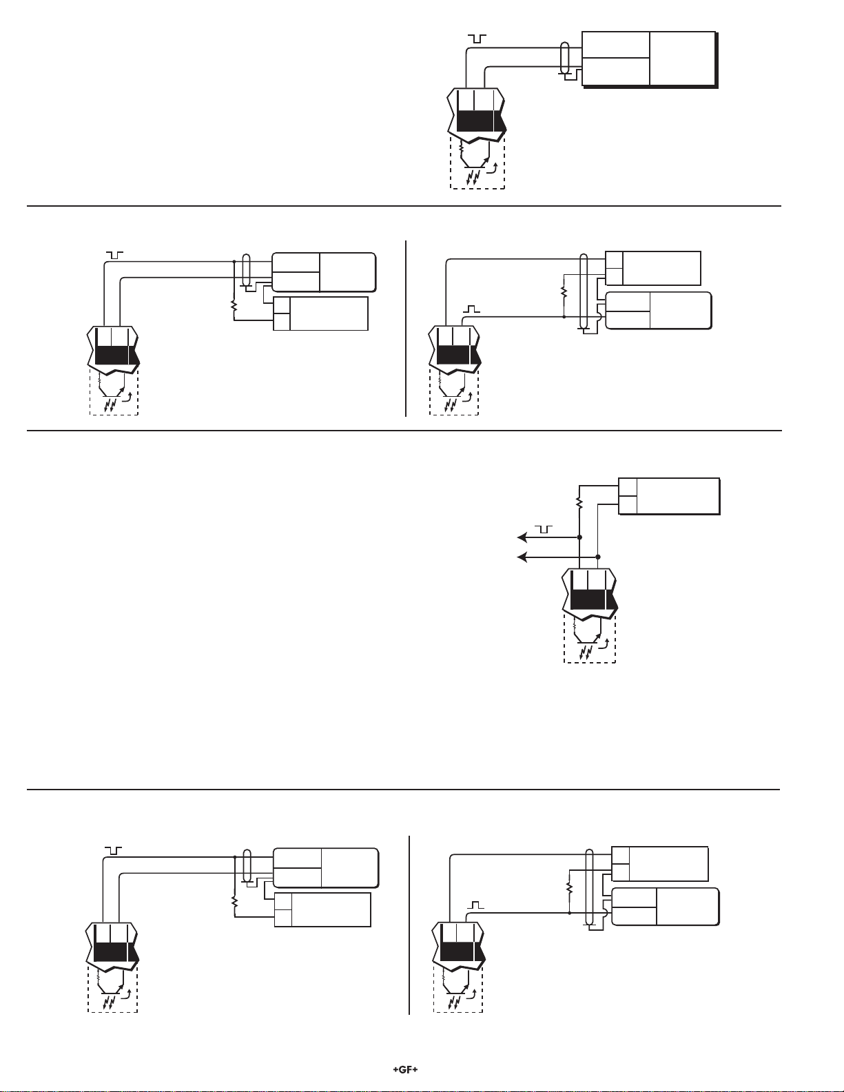
Sensor (PLS) Auxiliary (AUX) pulse outputs:
• Open-collector transistor, optically isolated, 5 mA max. sink,
28 VDC max. pull-up voltage, programmable (AUX) pulse width
Totalizer reset: Front keypad or external contact closure,
30 m (100 ft) max cable length
• External contact closure overrides security feature (sec. 5)
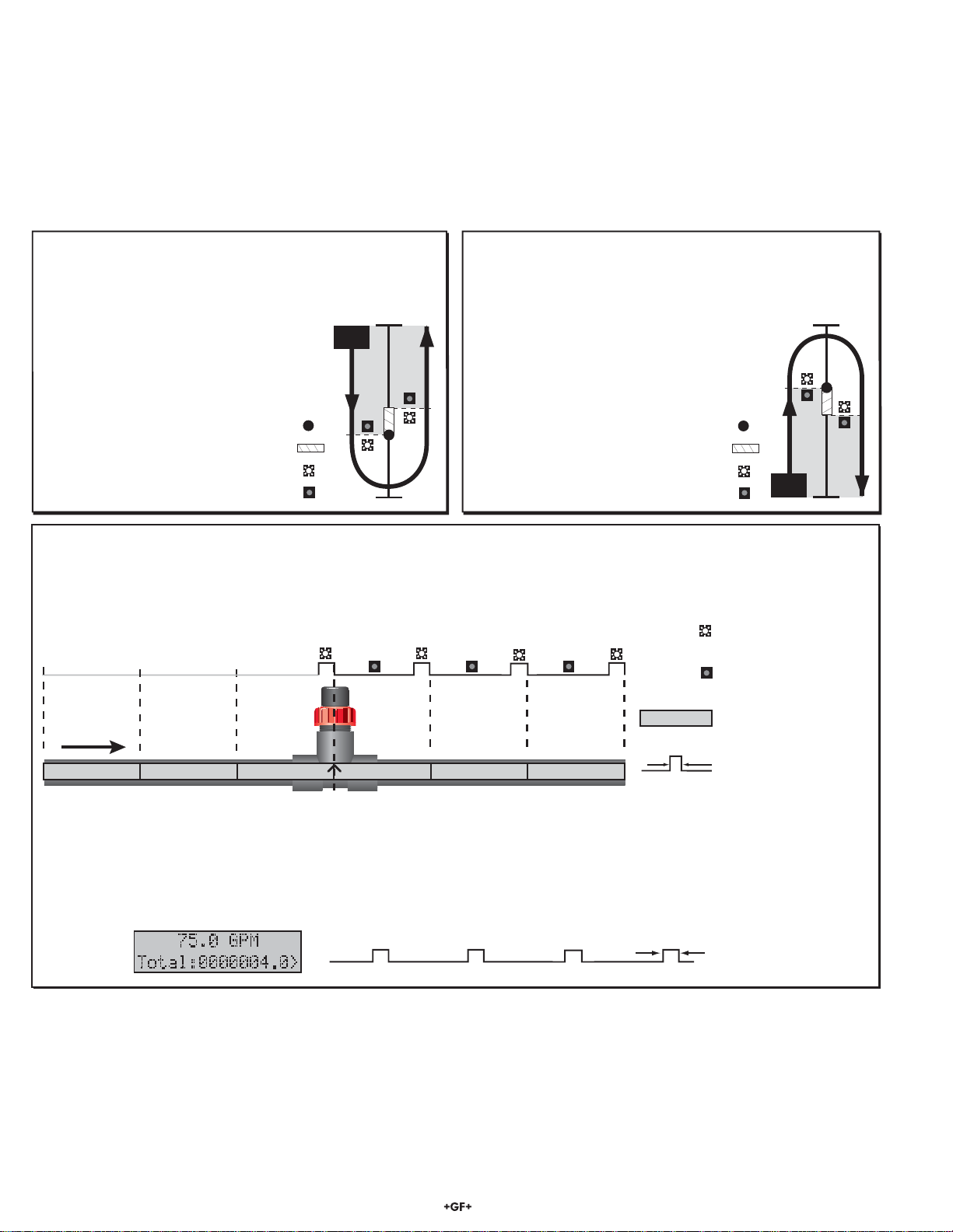
General
Sensor
compatibility: All Signet flow sensors
Accuracy: ±0.5% of reading
Input: Optically isolated
Enclosure:
• Rating: NEMA 4X/IP65 front
• Dimensions: 1/4 DIN, 96 x 96 x 88 mm (3.8 x 3.8 x 3.5 in.)
• Case material: ABS plastic
• Keypad: Sealed 4-key silicone rubber
• Weight: Approximately 500 g (18 oz.)
Display:
• Type: Microprocessor controlled air-core meter
movement and backlit alphanumeric 2 x 16 LCD
• Update rate: Flow = 1s, totalizer = < 200 ms
• Contrast: User selected, 5 levels
• Annunciators: 2 LEDs
Totalizers:
• 8-digit resettable with security option
• 8-digit non-resettable
Environmental
Operating temp.: -10 to 55 °C (14 to 131 °F),
50 °C (122 °F) max. with optional rear cover
Storage temp.: -15 to 80 °C (5 to 176°F)
Rel. humidity: 0 to 95%, non-condensing
Altitude: 4000 m max.
Pollution degree: 2
Noise immunity: EN50082-2
Noise emissions: EN55011
Safety: EN61010-1
Agency Approvals
• CE, UL, CUL
• Manufactured under ISO 9001 for Quality and
ISO 14001 for Environmental Management.
• Power supply, 115 VAC - 24 VAC, #3-5000.075
• Front snap-on bezel, #3-5000.525 (code 198 840 226)
• Assorted flow unit/multiplier decals, #3-5500.611 (code 198 840 230)
• 5500 instruction sheet #3-5500.090-1 (code 198 869 914)
10. Parts and Accessories
Optional surface mount bracket
#3-5000.598 (code 198 840 225)
Splashproof rear cover
#3-5000.395 (code 198 840 227)
5 x 5 inch adapter plate for Signet retrofit
#3-5000.399 (code 198 840 224)
Internal
PLS/AUX
circuits
+
GND
5500 rear PLS/AUX
output terminals
100Ω
11. Specifications
China RoHS (Go to www.gfsignet.com for details)
9
Signet 5500 Flow Monitor
Dimensions
SIDE VIEW
Mounting Clamp (2 ea.)
Optional Splashproof Rear Cover
88 mm
(3.5 in.)
Mounting Panel
Panel
Gasket
91 mm
(3.6 in.)
76 mm (3 in.)
88 mm (3.5 in.)
96 mm (3.8 in.)
VIEW Menu Setup Parameters (sec. 9.1)
88 mm
(3.5 in.)
88 mm (3.5 in.)
4-20
mA
Tot al
reset
AUX
output
PLS
output
12
Gnd
-
+
+
+
NC
C
NO NC
C
NO
-
+
Gnd
Freq. IN
Sen. Pwr.
Freq. IN
Iso. Gnd
Std. Sensor
Relay 1Relay 2
Patent No. D376,328
Flow
Open Collector
Sensor
12-24 V
10 W
Signet
Model #3-5500
LISTED
77CJ
UL
®
Rear
View
12. Quick Reference Menu Parameters
96 mm
(3.8 in.)
Front
View
96 mm (3.8 in.)
RELAY 2
RELAY 1
ENTER
4
0
1
2
3
5 6 7
8
9
10
GPM
Signet Monitor
92 x 92 mm
(3.62 x 3.62 in.)
Panel cutout
Menu Parameters Display Description Range Factory Default
A. • Flow rate and units
• Resettable total
00.000 - 99999. GPM
000000.00 - 99999999.
0000.0
0000000.0
B. Permanent total 000000.00 - 99999999. 0000000.0
C. Current loop output 3 - 21 mA N/A
D. Min Max meter
and dial range 00.000 - 99999. 0.000 - 100.00
E. • Relay 1 mode
• Relay 1 setpoint
Low or High, 0.0000 - 99999.
Pulse, 0.0001 - 99999.
Low
10.000 GPM
F. • Relay 2 mode
• Relay 2 setpoint
Low or High, 0.0000 - 99999.
Pulse, 0.0001 - 99999.
High
90.000 GPM
G. • AUX output mode
• AUX output setpoint
Low or High, 0.0000 - 99999.
Pulse, 0.0001 - 99999.
Pulse
1.0000 Gallons
H.
Last calibration date 00-00-00 to 39-39-99 01-01-98
10 Signet 5500 Flow Monitor
Relay mode
and setpoint
displays repeat
for relay 2
setup
CALIBRATE Menu Setup Parameters (sec. 9.2)
_ = blank
display digit
option
_ = blank
display digit
option
Menu Parameters Display Description Range Factory Default
A. Flow unit = digits 1-3
Flow timebase = digit 4
Aa - Zz, 0 - 9, _;
Mm, Ss, Hh, Dd _GPM
B. Min max range 00.000 - 99999. 00.000 - 100.00
GPM
C. Flow K-Factor 0.0001 - 99999. 60.000
D. Total units Aa - Zz, 0 - 9, _
(8 digits max) _Gallons
E. Total K-Factor 0.0001 - 99999. 60.000
F. • Relay 1 mode
• Relay 1 setpoint
Low or High, 0.0000 - 99999.
Pulse, 0.0001 - 99999.
Low
10.000 GPM
G. • Relay 1 Hysteresis
• Hysteresis volume 0.0000 - 99999. 2.0000
GPM
H. • Relay 1 mode
• Relay 1 pulse volume
Pulse
0.0001 - 99999.
10.000
Gallons
I. Relay 1 pulse width 0.10 - 999. seconds 10.0
seconds
J. • AUX output mode
• AUX output setpoint Low or High, 0.0000 - 99999. Low
1.0000
K. AUX output hysteresis
volume 0.0000 - 99999. 0.0000
L. • AUX output mode
• AUX output setpoint Pulse, 0.0001 - 99999. 1.0000
Gallons
M. AUX output pulse width 0.10 - 9999. seconds 0.10 seconds
N.
Last calibration date 00-00-00 to 39-39-99 01-01-98
11
Signet 5500 Flow Monitor
Menu Parameters Display Description Range Factory Default
A. Display contrast 0 to 5 3
B. Flow decimal **.*** to *****. ****.*
C. Totalizer decimal ******.** to ********. *******.*
D. Display averaging Off = 0 sec, Low = 4 sec.,
High = 8 sec. Off
E. 4 mA setpoint Unlimited 0.0000 GPM
F. 20 mA setpoint Unlimited 100.00 GPM
G. 4 mA adjust 3.0 to 5.0 mA 4.00 mA
H. 20 mA adjust 19 to 21 mA 20.00 mA
I. VIEW menu total reset
access code On or Off Off
J. AUX output pulse logic Active Low or Active High Low
OPTIONS Menu Setup Parameters (sec. 9.3)
Georg Fischer Signet LLC, 3401 Aerojet Avenue, El Monte, CA 91731-2882 U.S.A. • Tel. (626) 571-2770 • Fax (626) 573-2057
For Worldwide Sales and Service, visit our website: www.gfsignet.com • Or call (in the U.S.): (800) 854-4090
For the most up-to-date information, please refer to our website at www.gfsignet.com
3-5500.090-1 Rev. L 01/12 English © Georg Fischer Signet LLC 2012
13. Troubleshooting
Display Problem Solution
-- -- -- -- Display timebase too large
Change flow timebase (S=Seconds, M=Minutes, H=Hours,
D=Days) in CALIBRATE menu to a smaller value (e.g. GPD to
GPM)
Check settings
for Relay X Relay 1 or 2 pulse width too large for
frequency input or pulse volume too small
Reduce Relay 1 or 2 pulse width setting (sec. 9.2 I) or increase
pulse volume setting (sec. 9.2 H)
Check settings
for AUX output Auxiliary output pulse width too large for
frequency input or pulse volume too small
Reduce auxiliary output pulse width setting (sec. 9.2 M) or
increase pulse volume setting (sec. 9.2 L).
Must be between
0.0001 - 99999
Relay 1, Relay 2, or Auxiliary output (AUX)
pulse volume setpoint must be within
0.0001 - 99999.
Enter volumetric setpoint within 0.0001 - 99999. engineering
units (sec. 9.2 H or 9.2 L)
Must be between
0.10 - 999
Relay 1, Relay 2, or Auxiliary output (AUX)
pulse width must be within 0.10 -
999 seconds
Enter pulse width within 0.10 - 999 seconds
(sec. 9.2 I or 9.2 M)
Flow K-Factor
can not be zero Flow display K-Factor cannot be zero Enter K-Factor greater than zero (sec. 9.2 C)
Total K-Factor
can not be zero Totalizer K-Factor cannot be zero Enter K-Factor greater than zero (sec. 9.2 E)
SETUP READ ERROR
Press any Key Power fault occurred while saving setup
menu entry
Press any key to reload factory defaults then reprogram flow
system setup parameters. Note: Totalizer displays remain
unchanged and will resume after instrument reset.
14. Maintenance
Clean the instrument case and front panel with a soft cloth and mild liquid soap solution.

Other manuals for Signet 5500

1

Other GF Measuring Instrument manuals

GF Signet 2580 FlowtraMag User manual

GF

GF Signet 2580 FlowtraMag User manual

GF Signet 8150 User manual

GF

GF Signet 8150 User manual

GF Signet 5500 User manual

GF

GF Signet 5500 User manual

GF Signet 5090 User manual

GF

GF Signet 5090 User manual

GF Signet 4150 User manual

GF

GF Signet 4150 User manual

GF signet 2551 User manual

GF

GF signet 2551 User manual

GF U1000 V2 User manual

GF

GF U1000 V2 User manual

GF Signet 2537 User manual

GF

GF Signet 2537 User manual

GF Signet 4150 User manual

GF

GF Signet 4150 User manual

GF 4630 User manual

GF

GF 4630 User manual

GF Signet 2750-1 User manual

GF

GF Signet 2750-1 User manual

GF U1000 V2 User manual

GF

GF U1000 V2 User manual

GF Signet 2552 User manual

GF

GF Signet 2552 User manual

GF Signet 276 Differential Series User manual

GF

GF Signet 276 Differential Series User manual

GF signet 2551 User manual

GF

GF signet 2551 User manual

GF 582 User manual

GF

GF 582 User manual

GF DSR 100 User manual

GF

GF DSR 100 User manual

GF Signet FlowtraMag 2580 Series User manual

GF

GF Signet FlowtraMag 2580 Series User manual

GF SIGNET 2550 User manual

GF

GF SIGNET 2550 User manual

GF U3000 V2 User manual

GF

GF U3000 V2 User manual

GF FlowtraMag GF 2581 User manual

GF

GF FlowtraMag GF 2581 User manual

GF U1000 V2 User manual

GF

GF U1000 V2 User manual

GF Signet 2552 User manual

GF

GF Signet 2552 User manual

GF PORTAFLOW 330 User manual

GF

GF PORTAFLOW 330 User manual

Popular Measuring Instrument manuals by other brands

Renishaw RMP600 quick start guide

Renishaw

Renishaw RMP600 quick start guide

Sennheiser UI 10 BL quick guide

Sennheiser

Sennheiser UI 10 BL quick guide

Eaton Power Xpert Meter 2000 quick start guide

Eaton

Eaton Power Xpert Meter 2000 quick start guide

MIB Flowmax 242i operating manual

MIB

MIB Flowmax 242i operating manual

ALTHEN NM1-ISU-IP-3L-24 Series manual

ALTHEN

ALTHEN NM1-ISU-IP-3L-24 Series manual

Z3 Technology Z3-MVPR-01 user manual

Z3 Technology

Z3 Technology Z3-MVPR-01 user manual

Cal Test Electronics CT4432 user manual

Cal Test Electronics

Cal Test Electronics CT4432 user manual

Bosch Zamo manual

Bosch

Bosch Zamo manual

Tektronix TRCP0300 user manual

Tektronix

Tektronix TRCP0300 user manual

Brainstorm Electronics SR-112 owner's manual

Brainstorm Electronics

Brainstorm Electronics SR-112 owner's manual

GeoMax Zoom 75 Series installation guide

GeoMax

GeoMax Zoom 75 Series installation guide

Domino F520i user guide

Domino

Domino F520i user guide

Agilent Technologies 2100 Bioanalyzer System Installation and safety guide

Agilent Technologies

Agilent Technologies 2100 Bioanalyzer System Installation and safety guide

ATAGO PAL-15S instruction manual

ATAGO

ATAGO PAL-15S instruction manual

Wilcoxon MachineryMate 800 operating guide

Wilcoxon

Wilcoxon MachineryMate 800 operating guide

DIOXCARE DX700 user manual

DIOXCARE

DIOXCARE DX700 user manual

ICP DAS USA PMD series user manual

ICP DAS USA

ICP DAS USA PMD series user manual

LaserLiner HandyLaser manual

LaserLiner

LaserLiner HandyLaser manual

manuals.online logo
manuals.online logoBrands
  • About & Mission
  • Contact us
  • Privacy Policy
  • Terms and Conditions

Copyright 2025 Manuals.Online. All Rights Reserved.