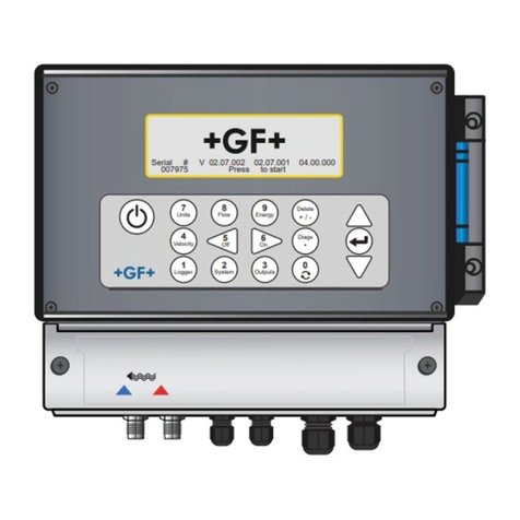
GF PORTAFLOW 330 User manual

Instruction manual
PORTAFLOW 330 - Portable Ultrasonic Flowmeter
GF Piping Systems


2
Original instruction manual
Observe instruction manual
The instruction manual is part of the product and an important element within the safety
concept.
Read and observe instruction manual.
Always have instruction manual available at the product.
Pass on instruction manual to all subsequent users of the product.

3
Contents
Original instruction manual............................................................................................................ 2
Contents........................................................................................................................................... 3
1Intended use .......................................................................................................................... 5
2About this document ............................................................................................................. 5
2.1 Warnings ................................................................................................................................ 5
2.2 Other related documents...................................................................................................... 6
2.3 Abbreviations ......................................................................................................................... 6
3Safety and responsibility ....................................................................................................... 6
4Transport and storage........................................................................................................... 7
5Design and function............................................................................................................... 7
5.1 Design .................................................................................................................................... 7
5.2 Portaflow 330 Instrument ..................................................................................................... 8
5.2.1 Connectors............................................................................................................................. 9
5.2.2 Keypad 10
5.2.3 Power supply and battery charging.....................................................................................11
5.3 Transducers..........................................................................................................................11
5.4 Principles of Operation.........................................................................................................12
6Installation ............................................................................................................................13
6.1 Transducer Positioning ........................................................................................................13
6.2 Transducer Attachment (Type ‘A’ & ‘B’)..............................................................................14
6.2.1 Preparation ...........................................................................................................................14
6.2.2 Attaching the guide rails ......................................................................................................15
6.2.3 Attaching the guide rails ......................................................................................................16
6.3 Installing the Data Logging Software..................................................................................17
7Operating Procedures ..........................................................................................................17
7.1 Setting-up the Instrument ...................................................................................................18
7.1.1 Using the instrument for the first time ...............................................................................18
7.1.2 Enabling/disabling the backlight .........................................................................................19
7.2 Using the Quick Start Menu .................................................................................................19
7.3 Using the System at a Regularly Monitored Location ........................................................22
7.4 Managing Named Sites ........................................................................................................24
7.4.1 Setting up a new site ............................................................................................................25
7.4.2 Changing a site name...........................................................................................................26
7.5 Instrument Calibration.........................................................................................................26
7.5.1 Adjusting the zero cut-off.....................................................................................................26

4
7.5.2 Adjusting the set zero flow offset ........................................................................................26
7.5.3 Adjusting the calibration factor ...........................................................................................27
7.5.4 Adjusting the roughness factor ...........................................................................................28
7.5.5 Adjusting the damping factor...............................................................................................29
7.6 Performing Monitoring & Logging Functions.....................................................................29
7.6.1 How to measure totalised flows (manually)........................................................................29
7.6.2 How to set up the basic logging application to memory ....................................................30
7.6.3 How to set up automatic (timed) logging mode..................................................................33
7.6.4 How to download logged data to a USB memory key.........................................................35
7.6.5 Transferring data to a PC.....................................................................................................36
7.7 Configuring the Current / Pulse Output ..............................................................................36
7.7.1 Current output ......................................................................................................................36
7.7.2 Pulse output..........................................................................................................................39
8Maintenance and Repair ......................................................................................................41
9Troubleshooting....................................................................................................................42
9.1 Overview ................................................................................................................................42
9.2 General Troubleshooting Procedure...................................................................................43
9.3 Warning & Status Messages................................................................................................44
9.4 Test Block .............................................................................................................................47
9.5 Microprocessor Reset Facility .............................................................................................47
9.6 Diagnostics Display ..............................................................................................................48
10 Appendix A: Specification.....................................................................................................49
11 Disposal.................................................................................................................................52

Instrction manual Intended use
5
1Intended use
The flowmeter is designed to work with clamp-on transducers to enable the flow of a liquid
within a closed pipe to be measured accurately without needing to insert any mechanical
parts through the pipe wall or protrude into the flow system. Using ultrasonic transit time
techniques, the Portaflow 330 is controlled by a micro-processor system which contains a
wide range of data that enables it to be used with pipes with an outside diameter ranging from
13mm up to 5000mm and constructed of almost any material. The instrument will also
operate over a wide range of fluid temperatures.
The flowmeter can be used to measure clean liquids or oils that have less than 3% by volume
of particulate content. Cloudy liquids such as river water and effluent can be measured along
with cleaner liquids such as demineralised water.
Typical applications
River water
Seawater
Potable water
Demineralised water
Treated water
2About this document
This document contains all necessary information for the installation, operation and service of
the product.
2.1 Warnings
In this instruction manual, warnings are used, which shall warn you of death, injuries or
material damage. Always read and observe these warnings!
Risk of fatal or serious injury!
There is a risk of fatal or serious physical injury if warnings are ignored!
Risk of damage to property!
Failure to comply leads to a risk of damage to property (loss of time, loss of data, machine
fault etc.)!
Further labels
Symbol
Meaning
1.
Call for action in a certain order: Here, you have to do something.
Call for action: Here, you have to do something
Listing
NOTICE
WARNING
CAUTION

Safety and responsibility Instruction manual
6
2.2 Other related documents
Georg Fischer planning fundamentals
These documents are available via the agency of GF Piping Systems or at www.gfps.com.
2.3 Abbreviations
Abbreviation
Description
ABS
Acrylonitrile-butadiene-styrene
DA
Double acting function
EMC
Electromagnetic Compatibility
FC
Fail safe to close function
FO
Fail safe to open function
LCD
Liquid crystal display
LED
Light-emitting diode
MOSFET
Metal oxide semiconductor field effect transistor
PB-
INSTAFLEX
Polybutene plastic piping system
PE-ELGEF
Polyethylene plastic piping system
PP-PROGEF
Polypropylene plastic piping system
PVDF-SGEF
PVDF (polyvinylidene fluoride) plastic piping system
SPNO
MOSFET
Single-pole normally open metal oxide semiconductor field effect transistor
VC-U-PVC
Polyvinyl chloride
3Safety and responsibility
Only use the product for the intended purpose, see Intended Use.
Do not use any damaged or faulty product. Sort out any damaged product immediately.
Make sure that the piping system has been installed professionally and that it is inspected
regularly.
Have the product and accessories installed only by persons who have the required
training, knowledge or experience.
Regularly train personnel on all questions regarding the locally regulations applying to
occupational safety and environmental protection, especially for pressurised pipelines.

Instrction manual Transport and storage
7
4Transport and storage
Protect the product against external forces during transport (impacts, knocks, vibrations
etc.).
Transport and / or store the product unopened in its original packaging.
Protect the product from dust, dirt, moisture as well as heat and ultraviolet radiation.
Ensure that the product is not damaged either by mechanical or thermal influences.
Before assembling, check the product for damage during transport.
5Design and function
5.1 Design
Legend
Pos.
Name
Pos.
Name
1
Test Block
7
Guide Rails (x2)
2
Transducer Cables (x2)
8
Transducers (Sensors Ax2, Bx2)
3
4-20mA / Pulse Output Cable
9
Ruled Separation Bars (x2)
4
Ultrasonic Couplant & Applicator
10
Portaflow 330 Instrument
5
Attachment Chains (x2)
11
USB Memory key
6
Power Supply (Batt.Charger)
The Portaflow equipment is supplied in a rugged IP67 carrying case fitted with a foam insert
to give added protection for transportation.

Design and function Instruction manual
8
Standard equipment
Portaflow 330 instrument with backlit graphic display.
Power supply - with UK, US, European adaptors. 110/240VAC.
4-20mA/Pulse Output cable.
USB memory key.
2 lengths of attachment chain each at 3.3 metres long.
Test block.
Transducer cables (x2) 2 metres long.
Transducer set 'A' (Transducers x2).
Transducer set 'B' (Transducers x2).
Set of guide rails for use with ‘A’ or ‘B’ transducers.
Ruled separation bar (2-piece).
Ultrasonic couplant.
Manual.
Optional equipment
Reflex mode
Transducer set 'D' –used for monitoring
pipes of 1500mm to 5000mm diameter,
over a temperature range -20°C to
+80°C. Kit is supplied in a separate case
and includes the sensors together with
ratchet straps and guide rails for
attaching to the pipe.
Magnetic guide rail kit, for use on mild
steel and cast iron pipes.
5.2 Portaflow 330 Instrument
The Portaflow 330 is a microprocessor controlled instrument operated through a menu
system using an inbuilt LCD display and keypad. It can be used to display the instantaneous
fluid flow rate or velocity, together with totalised values, or act as a data logger. When
operating in the data logger mode, the logged data can be stored in the instrument’s non-
volatile memory for downloading to a USB key at a later time. Up to 200k logging events can
be stored internally.
The instrument can also provide a variable current or variable ‘pulse’ (volumetric or
frequency) output that is proportional to the detected flow rate. This output can be calibrated
to suit a particular flow range and used with a range of external interface devices such as
those found in BMS or site monitoring systems.

Instrction manual Design and function
9
5.2.1 Connectors
Legend
Pos.
Name
Pos.
Name
1
Battery Charger
5
LCD Display
2
4-20mA / Pulse Output
6
Keypad
3
USB Socket
7
Reset pin-hole
4
Transducer Cables
Transducer connections
The transducers are connected to two colour-coded miniature coaxial sockets located on the
top of the instrument. Using the red/blue connector cables provided, the upstream
transducer should always be connected to the RED socket and the downstream transducer to
the BLUE one for a positive flow reading. It is safe to connect or disconnect the cable while
the instrument is switched on.
USB Socket
A standard USB socket is provided to enable logged data stored in the Portaflow 330 to be
transferred to a USB memory key.
4-20mA and Pulse output connection
The 4-20mA / ‘pulse’ output cable should be connected to the green 7-pin connector on the
top of the flowmeter, as shown in Figure 1.4. A single cable that can be adapted for use for
either of these output functions is included in the Portaflow 330 kit. The ‘tails’ on the free end
of the cable must be terminated to suit the intended application.
Red –4-20mA positive
Black –4-20mA negative
White –Pulse output
Green –Pulse return
Thick Black –Cable screen
Battery charger connection

Design and function Instruction manual
10
The supplied battery charger is connected to the instrument by means of the grey 2-pin
connector on the bottom of the unit.
The above connectors have different key-ways to prevent incorrect cable connection.
5.2.2 Keypad
Legend
Pos.
Name
Pos.
Name
1
ON/OFF
5
Scroll up
2
Scroll left
6
Enter (select)
3
Scroll right
7
Scroll down
4
Numerical keypad with dual function
keys
ON/OFF Key
The ON/OFF key is shown on the top left of the keypad. When turned ON an initialisation
screen is displayed on the LCD showing the instrument’s serial number and software revision.
Once this appears, the instrument can be started by pressing the ENTER key once –the
initialization screen is then replaced by a MAIN MENU which provides access to the remaining
functions.
Menus and the menu selection keys
The Portaflow 330 menus are arranged hierarchally with the MAIN MENU being at the top
level. Menu navigation is achieved by three keys on the right hand side of the keypad which
are used to scroll UP and DOWN a menu list and SELECT a menu item. When scrolling
through a menu an arrow-shaped cursor moves up and down the left hand side of the screen
to indicate the active menu choice which can then be selected by pressing the ENTER
(SELECT) key.
Some menus have more options than can be shown on the screen at the same time, in which
case the ‘overflowed’ choices can be brought into view by continuing to scroll DOWN past the
bottom visible item. Menus generally ‘loop around’ if you scroll beyond the first or last items.
If you select Exit it usually results in taking you back one level in the menu hierarchy, but in
some cases it may go directly to the ‘Flow Reading’ screen.
Some screens require you to move the cursor left and right along the display as well as up
and down. This is achieved using keys 5 (scroll LEFT) and 6 (scroll RIGHT).
NOTICE

Instrction manual Design and function
11
Dual function numerical keypad
The block of keys shown in the centre of the keypad in Figure 1.5 are dual function keys. They
can be used to enter straight-forward numerical data, select the displayed flow units or
provide quick access to frequently required control menus.
5.2.3 Power supply and battery charging
Operating power is provided by an internal battery that can be charged from the utility supply
using the supplied external charger. When you first receive the unit you must put the battery
on charge for a minimum of 6.5hrs before use. A fully charged battery will power the
instrument for up to 20hrs depending on the output utilisation and backlight usage.
The backlight can be selected to be either permanently OFF, illuminated for 10 seconds, 30
seconds or 1 minute every time a key is pressed, or permanently ON –as configured in the
Setup Instrument menu. If the backlight is active continuously it will reduce the available
battery operating time to 8hrs. Similarly, if the 4-20mA output is used constantly at 20mA, the
battery life would reduce by 50%. It is therefore beneficial to turn off the backlight and 4-
20mA output facilities when they are not required.
When the instrument is operating in the ‘Flow Reading’ mode the percentage battery charge
level is displayed symbolically on the LCD screen. A warning message is triggered if the
charge falls to approximately 30%, at which point there is up to four hours of battery
operation remaining, depending on usage. The battery can be charged both while the
instrument is in use or when switched off. The instrument’s internal data is stored in non-
volatile memory and will not be lost even if the battery discharges completely.
The battery is not a user-changeable item. The instrument must be returned to your
distributor if the battery needs replacing.
Only use the supplied charger, or special adaptor lead. Failure to comply with this will
invalidate your warranty.
5.3 Transducers
Two sets of ultrasonic transducers are provided as standard. When setting up the instrument
it will indicate the appropriate transducer set to use for a particular application, depending on
data entered by the user. Default pipe ranges are programmed into the instrument and most
of the time there will be no need to use an alternative transducer set to the one suggested by
the instrument. However, if circumstances dictate that a different set must be used it is
possible to manually programme the instrument to accept the alternative set.
Transducer set 'A'
Supplied as standard for use on pipes 13mm to 115mm outside diameter.
Transducer set 'B'
Supplied as standard for use on pipes 50mm to 2000mm outside diameter.
Transducer set 'D'
Type 'D' transducers are optional equipment that can be used by the Portaflow 330 on pipes
from 1500mm to
5000mm. They are supplied complete with ratchet straps for ‘diagonal mode’ attachment.
NOTICE

Design and function Instruction manual
12
5.4 Principles of Operation
When ultrasound is transmitted through a liquid the speed at which the sound travels through
the liquid is accelerated slightly if it is transmitted in the same direction as the liquid flow and
decelerated slightly if transmitted against it. The difference in time taken by the sound to
travel the same distance but in opposite directions is therefore directly proportional to the
flow velocity of the liquid.
The Portaflow 330 system employs two ultrasonic transducers attached to the pipe carrying
the liquid and compares the time taken to transmit an ultrasound signal in each direction. If
the sound characteristics of the fluid are known, the Portaflow microprocessor can use the
results of the transit time calculations to compute the fluid flow velocity. Once the flow
velocity is known the volumetric flow can be easily calculated for a given pipe diameter.
The Portaflow system can be set up to operate in one of four modes determined mainly by the
pipe diameter and the type of transducer set in use. The diagram below illustrates the
importance of applying the correct separation distance between the transducers to obtain the
strongest signal.
Reflex mode
This is the mode most commonly used. The two
transducers (U & D) are attached to the pipe in
line with each other and the signals passing
between them are eflected by the opposite pipe
wall.
The separation distance is calculated by the
instrument in response to entered data
concerning the pipe and fluid characteristics.
Reflex mode (double bounce)
In this mode the separation distance is
calculated to give a double bounce. This is
most likely to occur if the pipe diameter is so
small that the calculated reflex mode
separation distance would be impractical for
the transducers in use.
Reflex mode (triple bounce)
This illustration goes one step further to show
a triple bounce situation. This would normally
apply when working with very small pipes
relative to the transducer range in use.

Instrction manual Installation
13
Diagonal mode
This mode might be selected by the instrument
where relatively large pipes are concerned. In
this mode the transducers are located on
opposite sides of the pipe but the separation
distance is still critical in order for the signals
to be received correctly. This mode might be
used with the standard ‘A’ & ‘B’ transducer
sets but for really large pipe installation the
optional transducer set ‘D’ might be
recommended.
6Installation
6.1 Transducer Positioning
In many applications an even flow velocity profile over a full 360° is unattainable due, for
example, to the presence of air turbulence at the top of the flow and possibly sludge in the
bottom of the pipe. Experience has shown that the most consistently accurate results are
achieved when the transducer guide rails are mounted at 45° with respect to the top of the
pipe.
The Portaflow equipment expects a uniform flow profile as a distorted flow will produce
unpredictable measurement errors. Flow profile distortions can result from upstream
disturbances such as bends, tees, valves, pumps and other similar obstructions. To ensure a
uniform profile the transducers must be mounted far enough away from any cause of
distortion such that it no longer has an effect. Montage
To obtain the most accurate results the condition of both the liquid and the pipe wall must be
suitable to allow the ultrasound transmission along its predetermined path. It is important
also that the liquid flows uniformly within the length of pipe being monitored and that the flow
profile is not distorted by any upstream or downstream obstructions. This is best achieved by
ensuring there is a straight length of pipe upstream of the transducers of at least 20 times
the pipe diameter and 10 times the pipe diameter on the downstream side. Flow
measurements can be made on shorter lengths of straight pipe, down to 10 diameters
upstream and 5 diameters downstream, but when the transducers are positioned this close to
any obstruction the resulting errors can be unpredictable.

Installation Instruction manual
14
Do not expect to obtain accurate results if the transducers are positioned close to any
obstructions that distort the uniformity of the flow profile.
6.2 Transducer Attachment (Type ‘A’ & ‘B’)
The use of chains to fix the guide rail to the pipe can be eliminated on steel pipes by using
the optional magnetic guide rails. In all other respects the setting up of the sensors is the
same as for standard guide rails.
Type ‘A’ & ‘B’ transducers are fitted to adjustable guide rails which are secured to the pipe
using wrap-around chains and mechanically connected together by a steel separation bar.
The separation bar also acts as a ruler to allow the distance between the transducers to be
accurately set to the value determined by the Portaflow instrument.
When fitting the guide rails it is easiest to assemble them onto the separation bar and adjust
to the required separation distance before attaching them to the pipe.
6.2.1 Preparation
1. Before you attach the transducers you should first ensure that the proposed location
satisfies the distance requirements shown in Figure 2.1 otherwise the resulting accuracy
of the flow readings may be affected.
2. Prepare the pipe by degreasing it and removing any loose material or flaking paint in
order to obtain the best possible surface. A smooth contact between pipe surface and the
face of the transducers is an important factor in achieving a good ultrasound signal
strength and therefore maximum accuracy.
NOTICE
NOTICE

Instrction manual Installation
15
6.2.2 Attaching the guide rails
Legend
Pos.
Name
Pos.
Name
A
Tensioning thumb-wheel
E
Ruler scale (0)
B
Tension bar
F
Set Separation distance
C
Separation bar securing screw
G
Securing chain
D
Separation bar
1. Slide the separation bar (D) into the front of the left hand guide rail, align the front edge of
the guide rail with ‘0’ on the ruler scale (E) and secure it in place by tightening the
thumbscrew (C).
2. Slide the other end of the separation bar into the front of the right hand guide rail, align
the front edge of the guide rail to the required separation distance (obtained from the
Portaflow instrument) on the ruler (F), then secure it in place by tightening the
thumbscrew.
If magnetic guide rails are used on steel pipes then only the location at 45° on the pipe
apply on the next two sections.
3. On each guide rail, attach one end of a securing chain to a hook on the tensioning bar (B),
wrap the chain around the pipe (G) and then attach it to the hook on the other end of the
tensioning bar whilst keeping the chain as tight as possible.
4. Rotate the complete guide rail assembly so that it is approximately 45° with respect to the
top of the pipe. Then tighten the chain by turning the tensioning thumb-wheel (A) on each
guide block until the assembly is securely attached to the pipe.
NOTICE

Installation Instruction manual
16
If you are unable to get sufficient tension on the chain to hold the assembly in place,
fully slacken the tensioning thumb-wheel and shorten the effective length of the chain
wrapped around the pipe by connecting the tensioning bar to the next link in the chain,
then re-tension.
6.2.3 Attaching the guide rails
Legend
Pos.
Name
Pos.
Name
A
Transducer cover plate.
D
Transducer cable connection
B
Transducer locating slot/lug.
E
Ultrasonic couplant application
C
Transducer cover plate securing
screw.
1. Slide the transducer cover plate (A) fully towards the outside of the guide assembly to
allow sufficient access to fit the transducer.
2. Clean the face of the transducer, removing all traces of dirt and grease.
3. Apply a 3mm bead of ultrasonic couplant along the centre length of the transducer (E).
4. Fit the transducer into the guide block –ensuring the lugs on the sides of the transducer
are correctly located into the slots on the sides of the guide block (B).
5. Slide the transducer cover plate (A) over the top of the transducer and tighten the
thumbscrew (C) finger tight to secure the transducer in place. When securing the cover
plate take care to leave sufficient room around the transducer connector (D) to connect
the cable.
6. Repeat the above steps for the second transducer.
7. Connect the transducers to the Portaflow instrument using the coaxial cables provided.
The RED cable must be connected to the upstream transducer and the BLUE cable to the
downstream transducer. If you observe a negative flow, swap the red and blue cables at
the sensor end.
NOTICE

Instrction manual Operating Procedures
17
6.3 Installing the Data Logging Software
The supplied USB memory key contains a copy of the Portagraph program (together with user
manual) which is used to display and save the logged data using a Microsoft based PC. The
manual should be copied to a PC and the Portagraph software installed before the system is
used to log data. A file on the USB key contains the instructions for installing the application.
Contact your local GF partner if the computer to be used is Apple based.
7Operating Procedures
Initial instrument setup
Battery charging, Set date/time, Language, Backlight
Connect and take basic flow readings
At a one-off location
At a frequent location
Manage site details
QUICK START
VIEW EDIT SITE DATA
Set up a named site
Rename a site
Enter data
Choose site /
check/edit data
Attach sensors
Attach sensors
FLOW READING
FLOW READING
Carry out any necessary calibration
How to adjust the Calibration Factor
How to adjust the Roughness Factor
How to adjust the Damping Factor
Set-up a monitoring or logging application
Configure the
interfaces/outputs
How to measure totalised flows
How to set up basic (manual) logging
How to set up auto-timed logging
How to download logged data
4-20mA ON/OFF
4-20mA Calibration
Pulse ON/OFF
Pulse calibration
Pulse frequency mode
Pulse frequency calibration

Operating Procedures Instruction manual
18
7.1 Setting-up the Instrument
7.1.1 Using the instrument for the first time
Before you use your Portaflow 330 for the first time you should first charge the battery, then
select the display language and set-up the internal clock, as described below.
Charging the battery
1. Connect the external battery charger to the
charger socket at the bottom of the
instrument then switch on the utility supply.
2. The instrument should indicate CHARGING
and an animated battery symbol indicates that
the battery is taking on charge.
3. Leave the instrument on charge for 6.5 hours
before using it for the first time.
Selecting a language
The first time you switch on the instrument you
may be asked to select a user language.
1. Switch on the instrument by pressing the
N/OFF button.
2. If necessary, select the required language
using the UP/DOWN scroll keys then press
the ENTER key.
3. The selected language will be the default
when the instrument is next used. To change
the language again select the Change
Language option in the SETUP INSTRUMENT
screen (see below)
4. The initialisation screen will be displayed,
giving details of the instrument’s serial
number and software revision details.
5. Press the ENTER key to start the instrument.
6. This is the MAIN MENU and is the starting
7. point for all the operations described in his
chapter.
Setting the Date & Time
1. Select Setup Instrument from the MAIN
MENU. The screen shown here should be
displayed.
2. Select Set Date & Time and click ENTER.
3. A flashing cursor should appear under the
first date number. Enter the date sequence in
dd-mm-yy order then press the ENTER key.

Instrction manual Operating Procedures
19
4. Repeat this action to set the time.
5. Select Exit then press the ENTER key to return
to the MAIN MENU.
If you make a mistake when entering the data press the Delete key to move the cursor back
to the number you wish to change, then continue. If you enter an invalid number an
‘ERR:Invalid Date or Time!’ error message is displayed on the second line of the screen. If
this occurs repeat the set date/time procedure.
7.1.2 Enabling/disabling the backlight
The backlight can be selected to be either Disabled, illuminated for 10 seconds, 30 seconds or
1 minute every time a key is pressed, or ON permanently. If the backlight is not required it is
recommended that you disable it to prolong the battery discharge time.
1. Select Setup Instrument from the MAIN
MENU.
2. Select Backlight from the SETUP
INSTRUMENT screen then press the ENTER
key.
3. Select the required backlight operation.
4. Press the ENTER key to return to the SETUP
INSTRUMENT screen.
5. Select Exit then press the ENTER key to return
to the MAIN MENU
7.2 Using the Quick Start Menu
the quickest way to set up the Portaflow system and access the FLOW READING screen. If the
point at which you intend to take the measurement is likely to require regular monitoring it is
best to set it up as a ‘Site’ within the Portaflow 330, which then stores the site parameters
Before you can use the Portaflow system you need to obtain the following details (this
information will be required when setting up the Quick Start menu):
The pipe outside diameter.
The pipe wall thickness and material.
The pipe lining thickness and material.
The type of fluid.
The fluid temperature.
NOTICE
Table of contents
Other GF Measuring Instrument manuals

GF
GF Signet 5500 User manual

GF
GF Signet 4150 User manual

GF
GF FlowtraMag GF 2581 User manual

GF
GF Signet 2580 FlowtraMag User manual

GF
GF Signet 2750-1 User manual

GF
GF JRG Coral force 8000 User manual

GF
GF 4630 User manual

GF
GF Signet 2552 User manual

GF
GF signet 2551 User manual

GF
GF signet 2551 User manual