2 2551 Magmeter
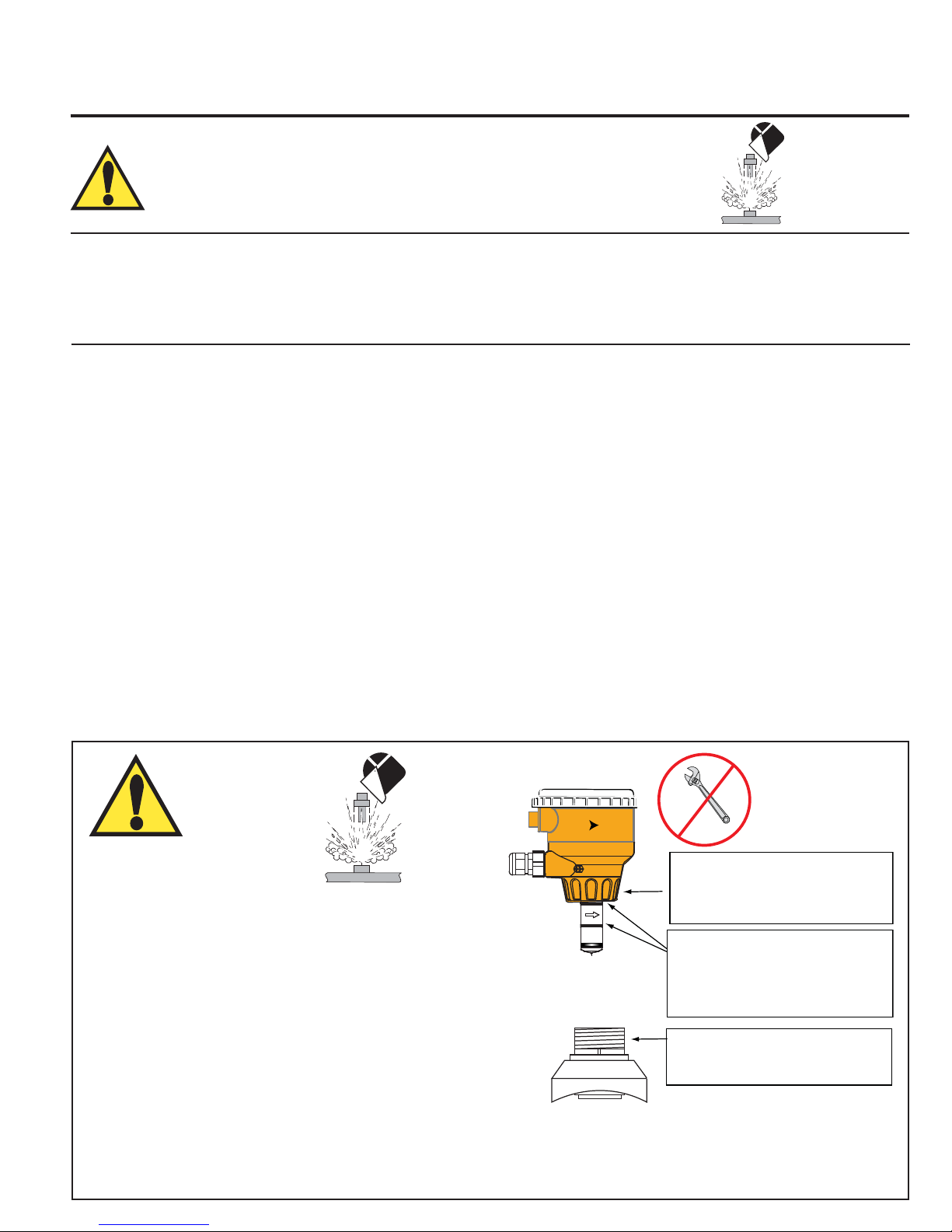
Wetted Materials:
• Sensor body and Electrodes and Grounding ring:
• -P0, -P1, -P2: Polypropylene and 316L SS
• -T0, -T1, -T2: PVDF and Titanium
• -V0, -V1,-V2: PVDF and Hastelloy-C
• -W0, -W1, -W2: PVDF and 316L SS
• O-rings: FPM (standard)
EPDM, Kalrez® (optional)
The user is responsible for determining the chemical
suitability of these materials for a specific application.
• Case: PBT
• Display window: Polyamide
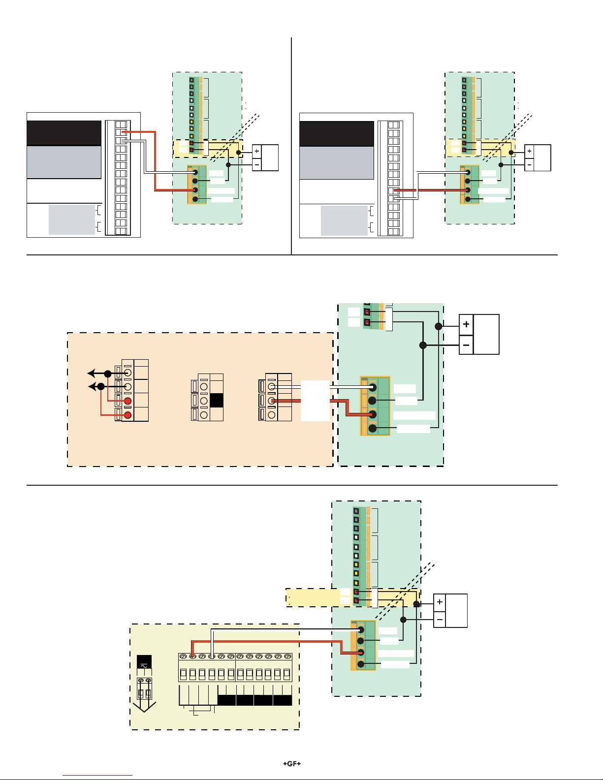
Power Requirements
• 4 to 20 mA: 21.6 to 26.4 VDC, 22.1 mA max.
400 mV p-p maximum ripple voltage
• Frequency: 5 to 26.4 VDC, 15 mA max.
• Digital: 5 to 6.5 VDC, 15 mA max.
• Auxiliary (only required for units with relays):
9 to 24 VDC, 0.4A max
• Reverse polarity and short circuit protected
Performance
• Pipe size range: DN15 to DN300 (½ to 12 in.)
• Flow Range Minimum: 0.05 m/s (0.15 ft/s)
(Bi-directional) Maximum: 10 m/s (33 ft/s)
• Linearity: ±1% of reading +0.01m/s (0.033 ft/s)
• Repeatability ±0.5% of reading @ 25°C (77°F)
• Minimum Conductivity: 20 μS/cm
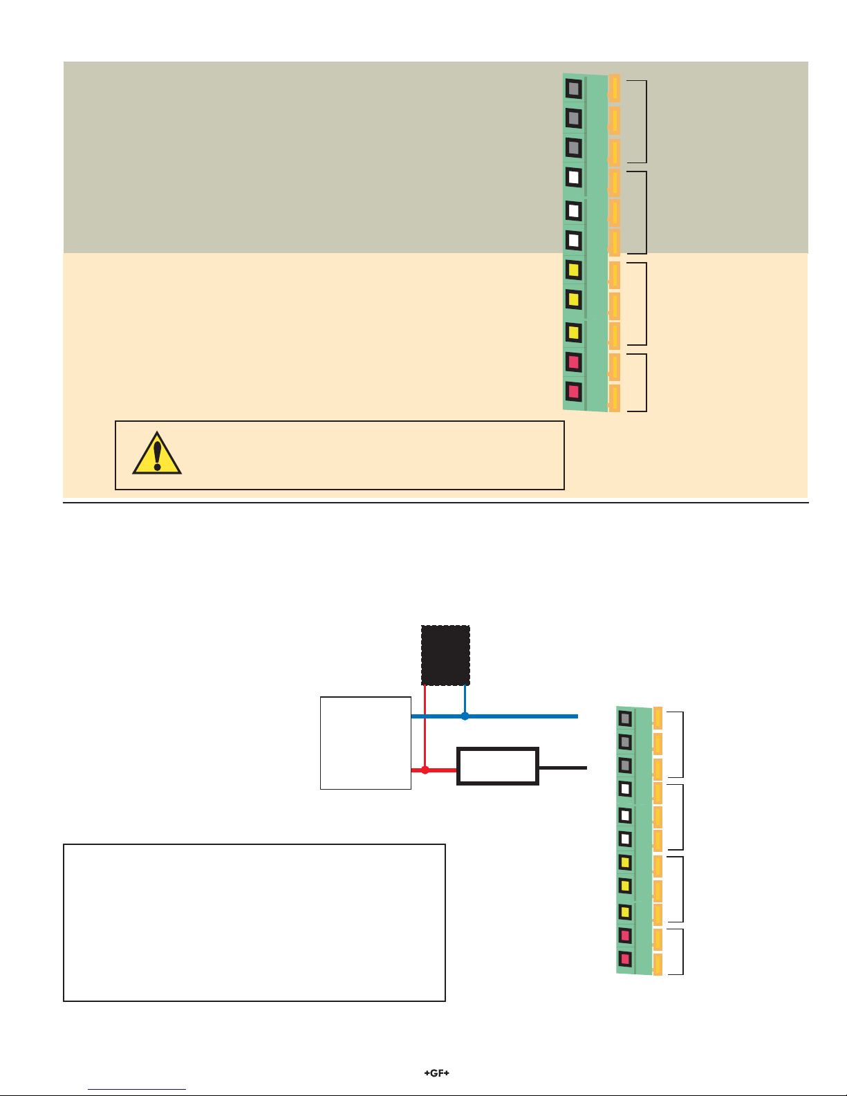
Output Specifications
Current output (4 to 20 mA)
• Max Loop Resistance: 300Ω
• Loop Accuracy: 32 μA max. error (25°C @ 24 VDC)
• Temp. drift: ±1 μA per °C max.
• Power supply rejection: ±1 μA per V
• Isolation: Low voltage <48 VAC/DC
from electrodes and aux power
• Maximum cable: 300 m (1000 ft.)
• Error condition: 22.1 mA
Frequency output:
• Output modes: Freq, Freq÷10, or Mirror Relay 1
• Max. Pullup Voltage: 30 VDC
• Reverse Polarity Protected to -40 V
• Max. Current Sink: 50 mA, current limited
• Maximum cable: 300 m (1000 ft.)
Digital (S3L) Output:
• Serial ASCII, TTL level 9600 bps
• Compatible with Signet 8900
Standards and Approvals
• CE
• UL, CUL (for display versions with relays)
• NEMA 4X / IP65 Enclosure (with cap installed)
• EMC: EN55011: 1998 +A1:99+A2:02
Class B Emissions
EN61326: 1997 +A1:98+A2:01
EN61000-6-2:2001
• Safety: EN61010-1:2001
• U.S. Patent No. 7,055,396 B1
2.0 Specifications
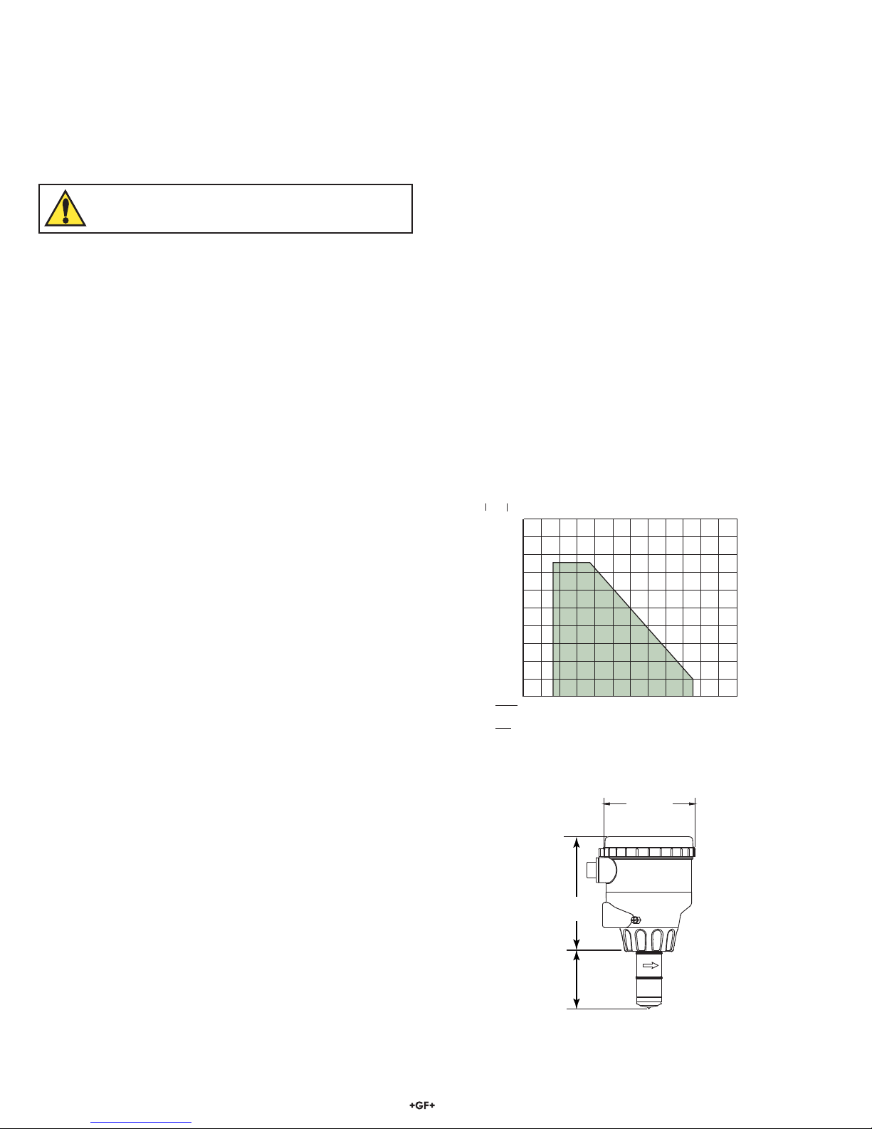
40
80
120
160
200
3
6
8
11
14
0 40 80 120 160 200
-18 4 27 49 71 93
°F
°C
psi
bar
240
115
2551
Pressure vs. Temperature
Media Temperature
Operating Pressure
2551
Acceptable
Media Range
Dimensions
116.8 mm
(4.6 in.)
-XO
-X1
-X2
95.3 mm
(3.75 in.)
Pipe Range
1/2 to 4 in. -XO = 58 mm (2.3 in.)
5 to 8 in. -X1 = 91 mm (3.6 in.)
10 to 12 in. -X2 = 167 mm (6.6 in.)
X = Sensor Body P, T, V, or W
Relay Specifications
• Relay 1 and 2 Type: Mechanical SPDT
Rating: 5 A @ 30 VDC max., 5 A @ 250 VAC max.
• Relay 3 Type: Solid State
Rating: 50 mA @ 30 VDC, 50 mA @ 42 VAC
Hysteresis: Adjustable, plus timer delay
Trigger Delay: Adjustable (0 to 9999.9 sec.)
Relay Modes: Off, Low, High, Window, and Proportional Pulse
Relay Source: Flow Rate, Resettable Totalizer
Error Condition: Selectable; Fail Open or Fail Closed
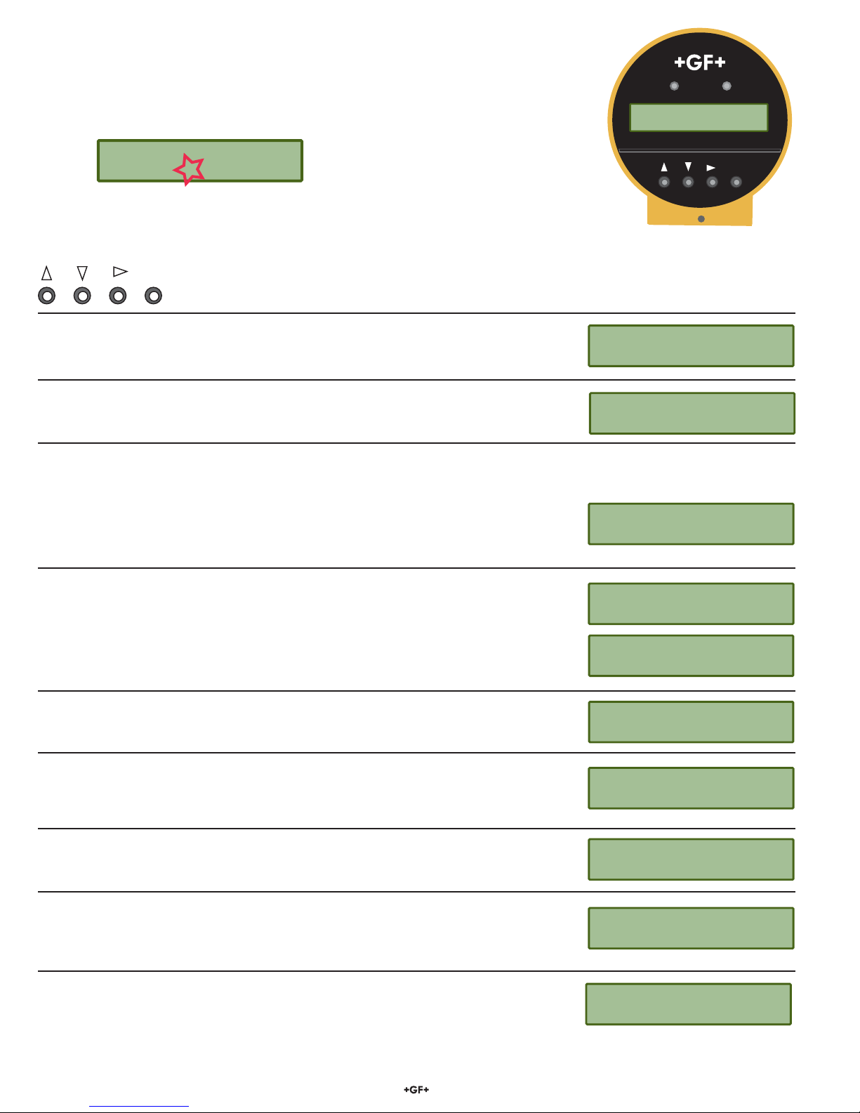
Display
Characters: 2 x 16
Contrast: User-set in four levels
Backlighting (only on relay versions):
Requires external 9-24 VDC, 0.4 mA max.
Environmental Requirements
Storage Temperature:
-20° to 70°C (-4° to 158°F)
Relative Humidity :
0 to 95% (non-condensing)
Operating Temperature
• Ambient: -10° to 70°C (14° to 158°F)
• Media: 0° to 85°C (32° to 185°F)
Max. operating pressure:
10.3 bar @ 25°C (150 psi @ 77°F)
1.4 bar @ 85°C (20 psi @ 185°F)