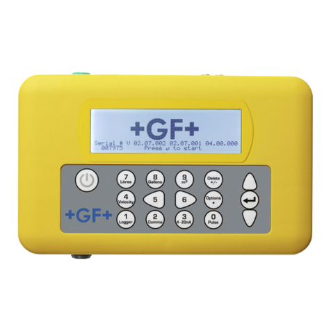
GF U3000 V2 User manual

GF Piping Systems
Modbus Supplement to the
operating instructions
GF U3000 V2 Ultrasonic Flowmeter
GF U3000 V2 HM Ultrasonic Heatmeter
2026161 F U3000 V2 Modbus Supplement
MA_00138 / EN / 00 (07.2022)
© Georg Fischer Piping Systems Ltd
CH-8201 Schahausen/Switzerland
+41 52 631 30 26/info.ps@georgfischer.com
www.gfps.com
7
Units
4
Velocity
1
Logger
8
Flow
6
On
5
Off
2
System
9
Energy
3
Outputs
Delete
+ / -
Diags
•
0
Serial # V 02.07.002 02.07.001 04.00.000
007975 Press to start

2
GF U3000 V2 Ultrasonic FlowmeterModbus Supplement to the operating instructions
Table of Contents
1 Intended use 3
2 MODBUS CONNECTIONS 3
3 MODBUS CONFIGURATION 4
3.1 Supported Messages 5
3.2 The Register Map. 6
3.3 Reading Registers 10
3.4 Writing Updateable Registers 10
3.5 General Procedure for Updating Unit Settings 11
3.6 Some Examples 12
3.7 Diagnostics 13
3.8 Read Device Identification 13
3.9 Status Flags 14
4 GLOSSARY 14
Original instruction manual
Disclaimer
The technical data are not binding. It does not constitute expressly warranted characteristics and neither guaranteed properties nor
guaranteed durability. It is subject to modification. Our General Terms of Sale apply.
Observe instruction manual
The instruction manual is part of the product and an important element within the safety concept.
►Read and observe instruction manual.
►Always have instruction manual available by the product.
►Give instruction manual to all subsequent users of the product.

3
GF U3000 V2 Ultrasonic Flowmeter Modbus Supplement to the operating instructions
1 Intended use
The type GF U3000 V2 Ultrasonic Flowmeter Modbus document is a supplement to the operating instructions.
2 MODBUS CONNECTIONS
The ideal Modbus network topology is that of a daisy chain as depicted in Figure 2. Small spurs may be used, but in this case attention
needs to be paid to the data rate and the number of units on the bus. It is recommended to run cable containing 4 wires and a shield
to each GF U3000 V2 Ultrasonic Flowmeter from a network junction box. This accommodates one pair of twisted wires into the con-
nected unit, and one set out to connect to the next unit.
It is the responsibility of the user to install cable and wire to the MULTICOMP MP002510 Modbus plug connector. The connection
diagram is shown below in Figure 1. Note that the connection polarity is all important. It is the user’s responsibility to ensure that the
A/+ve and B/-ve connections to all units are consistent.
1 2
3
GND
A / +ve B / -ve
Rear View of Multicomp Pro
MULTICOMP MP002510
Rear Solder Lug View
G2.1 Figure 1 - GF U3000 V2 Ultrasonic Flowmeter Modbus Plug Connections
For reliable operation of a Modbus network the cable type and installation must comply with requirements in the Modbus specifica-
tion document:
MODBUS over Serial Line Specification & Implementation guide V1.02
CAUTION!
This output is suitable for SELV circuits only!
For full immunity to electrical interference the screen of the Modbus cable should be connected to Earth.

4
GF U3000 V2 Ultrasonic FlowmeterModbus Supplement to the operating instructions
Three wire Weipuplug/
socket orblock
connector
U3000 U3000 U3000
G2.2 Recommended Modbus Network Toplogy
3 MODBUS CONFIGURATION
The Modbus board supplied with the GF U3000 V2 Ultrasonic Flowmeter complies with the Modbus Application Protocol Specification
V1.1b3 and Modbus over Serial Line Specification and Implementation V1.02. Copies of these documents can be found at
https://modbus.org/docs/Modbus_Application_Protocol_V1_1b3.pdf
and
https://modbus.org/docs/Modbus_over_serial_line_V1_02.pdf
respectively.
Only the mandatory RTU mode is supported for the GF U3000 V2 Ultrasonic Flowmeter.
The Modbus specification for RTU-mode defines an 11-bit character frame containing an 8-bit character. If Parity is used, then only
one stop bit is required. If parity is not used, then two stop bits must be specified. In addition to the standard frame format, non-
standard 10-bit frames are also supported. In this case the GF U3000 V2 Ultrasonic Flowmeter will issue warnings but not prohibit
the use of these formats.
The board supports the following baud-rate and parity combinations:
Baud Rate Data Bits Parity Stop Bits
300 8 E, O, N 1, 2
600 8 E, O, N 1, 2
1200 8 E, O, N 1, 2
2400 8 E, O, N 1, 2
3600 8 E, O, N 1, 2
4800 8 E, O, N 1, 2
7200 8 E, O, N 1, 2
9600 8 E, O, N 1, 2
14K4 8 E, O, N 1, 2
19K2 8 E, O, N 1, 2
28K8 8 E, O, N 1, 2
38K4 8 E, O, N 1, 2
57K6 8 E, O, N 1, 2
76K8 8 E, O, N 1, 2
115K2 8 E, O, N 1, 2
230K4 8 E, O, N 1, 2

5
GF U3000 V2 Ultrasonic Flowmeter Modbus Supplement to the operating instructions
Baud rate and other options may be set in the Modbus Setup menu (Setup Instrument | Modbus..)
Default frame settings are as per the Modbus specification of 19200 baud, even parity and one stop bit.
In the Modbus Setup menu, the user may set the Modbus address, the baud rate, frame format and other parameters. Note that only
RTU mode is possible at the time of writing, and as such, an 8-bit byte is the only sensible selection. If 7 bits are selected in RTU
mode, then a beep will sound, and the baud rate will change to the default. Warnings will be generated if the frame format is non-
standard, but the settings may still be used. Modbus addresses may be between 1 and 247.
While some GF U3000 V2 Ultrasonic Flowmeter parameters are configurable via a management system, GF U3000 V2 Ultrasonic
Flowmeter local mode takes precedence. To stop a management system changing configuration while operating in local mode, set
Block All Remote Changes, or Block Remote Total Changes as appropriate, in the Modbus Setup menu. Blocking all remote changes
includes blocking of total changes.
When complete select Save, Configure and Exit.
3.1 Supported Messages
The following message types are supported from the Modbus Application Protocol Specification:
Message Type Message
Number Notes
READ HOLDING REGISTERS 03 (0x03) Read a contiguous block of registers.
WRITE SINGLE REGISTER 06 (0x06) Write to a single register.
WRITE MULTIPLE REGISTERS 16 (0x10) Write to multiple registers in one transaction.
MASK WRITE REGISTER 22 (0x16)
Bits within writable registers may be set or reset with this command.
E.g., to set bit 2, set the AND mask to 0xFFFB (bit 2 low) and the OR mask to 0x0004
(bit 2 high). To clear bit 2 set the AND mask to 0xFFFB and the OR mask to 0x0000.
In general, set all bits in the AND mask to 1 except for the bit positions you wish to
modify. Set the matching bit positions in the OR mask to the value you want the bit
position to hold.
READ WRITE MULTIPLE REGISTERS 23 (0x17)
This command allows the write and subsequent read of two, possibly disjoint sets
of registers. The write operation is performed before the read operation as per the
Modbus Application Protocol Specification.
DIAGNOSTICS 08 (0x08)
Only the following sub functions:
00 Return Query Data
01 Restart Communications
04 Force Listen Only Mode
READ DEVICE IDENTIFICATION 43/14
(0x2B/0x0E)
Support to Conformance level 0x82 (Basic and Regular Identification – Stream and
individual Access).
G2.3 Modbus Messages Supported
None of these messages are supported in broadcast mode (i.e., writes to address zero).

6
GF U3000 V2 Ultrasonic FlowmeterModbus Supplement to the operating instructions
3.2 The Register Map.
A GF U3000 V2 Ultrasonic Flowmeter Modbus register is depicted in Figure 3. A few points need to be noted. The interpretation of
Modbus registers or register sets is important. All data is in BIG ENDIAN format. In BIG ENDIAN format the most significant portion
of a number is stored in the lower addresses. To help visualise BIG ENDIAN format see Figure 3. Each register is a 16-bit quantity
whose size is often referred to as a word.
Register Register Register
Register Offset Address
0 1 2 3
Bit 0 LSBbit
MSBit
MSByte LSBbyte(s)
MSWord LSWord
Bit 15
LSBbit
MSBit
Bit 0
Bit 15
MS – Most Significant
LS – Lower or least significant
G2.4 Big Endian Data Format
Used datatypes:
Datatype
uint16 An unsigned 16-bit value
int16 A signed, 2’s complement 16-bit value
In addition to this, two consecutive registers may be used in conjunction to represent larger types. The following 32-bit quantities are
supported:
Datatype
uint32 An unsigned 32-bit value
int32 A signed, 2’s complement 32-bit value
IEEE 754 SP An IEEE754, single precision, 32-bit floating point number
Note that as with big endian format the most significant word is found in the lower address as depicted in Figure 3. To illustrate this,
the 32-bit, unsigned value 0xA9871023 will be stored with the value 0xA987 in the lower address (oset) and the value 0x1023 will
be stored in the higher address (oset). The same applies to an IEEE754 SP number. The sign, exponent and 7 most significant man-
tissa values are stored in the lower address. The lower precision 16-bits of the mantissa are stored in the higher address.
Some registers below contain bit-mappings. These values may be manipulated via the MASK WRITE REGISTER (command 22) as
outlined in Table 1. Bit fields are numbered from zero starting with the first definition within the register. The number after the colon
represents the number of bits in this field.
The register map is broken into two blocks. The first is a set of registers that provide access and / or control to basic instrument
settings. This block starts at register address 0 and comprises 10 registers (registers 1 to 10). Register 1 (address 0) contains a
check value of 0x5A in the upper byte and an interface version number starting at the value 0. It may be that the register map could
change in future. In this case the management system programmer may read the lower byte and select a dierent register map to
that outlined below. Documentation will accompany any changes to the register map. The intended purpose of this is to allow a ma-
naged system with newer units to operate successfully with units containing older interfaces.
Registers 11 and 12 should not be used and the details provided illustrate the intended, unimplemented purpose.
Registers 13 to 100 are not implemented but if read, they will return the value zero.
Actual flow data starts at register 101 or oset 100 and continues to register 150. Within this range several registers are reserved
and should not be used. Registers 151 to 200 are not implemented but if read, they will return the value zero. Likewise, all registers
from 201 t0 300 are reserved for a second flow board should it be added later. If registers in this range are read, they will return 0.
The Time and Date registers at the start of the block is a duplicate of the value in the Time and Date register in the Instrument setting.

7
GF U3000 V2 Ultrasonic Flowmeter Modbus Supplement to the operating instructions
The management system programmer may choose to use the Time and Date associated with the GF U3000 V2 Ultrasonic Flowmeter,
or use the Time and Date associated with their system time by simply reading a block of registers starting at either oset 100 or
oset 104.
All data in the register set changes once each second. All registers should be read at the same time; however, it is possible to halt
the update of these registers before reading to allow the management system to read individual registers at its leisure. In this way,
it is guaranteed that all data points during the read will pertain to the same set (the same second).
It should be noted that if reading these registers takes more than a second, the time and Date stamp will jump and data for the mis-
sing second will be lost. Readings must be made in real time.
GF U3000 V2 Ultrasonic Flowmeter Modbus Register Map.
Reg
Num
Reg
Idx Use Type Notes Access1 Source/Comment
1 0
Check
value /
Interface
version
uint16 0x5A00 R
This is a check value and an interface
version number. This version is zero. All
values start at the base 0x5A00.
2 1 Device ID uint16
GF U3000 V2 Ultrasonic
FlowmeterC=0x0035
GF U3000 V2 Ultrasonic
FlowmeterHC=0x0036
GF U3000 V2 Ultrasonic
FlowmeterCO=0x0037
GF U3000 V2 Ultrasonic
FlowmeterHCO=0x0038
R GF U3000 V2 Ultrasonic Flowmeter
variant.
3,4 2,3 Serial
Number
uint32 E.g., 20111
0x0000, 0x4E8F
R Unit Serial Number
5 4 Regime uint16
Measurement Regime:3 RW
0 = Metric1
1 = Imperial
2 = US Imperial
3 = Metric2
> 3 = reserved (defaults to Metric1)
Temperature Regime: 1 0 = ⁰C,
1 = ⁰F
Reserved:11 For future use.
6 5
Instru-
ment
Control
Flags
uint16
Lock-out updates:1 RW
Writable from MBM only. 1= stop
updating registers (excludes action/
response bits)
Lock screen mode:1 Can be set/reset from MBM. Set Lock
screen mode active= 1
Update Lock Screen Mode:1 Action/Response bit. 1=update; set to 0
by instrument when complete.
Save Measurement Regime:1 Save the current measurement
regimes. (including temperature)
Reserved:12
7 6
Instru-
ment
General
Flags
uint16
Screen lock mode active:1 R Local screen is locked
Remote Lockout:1
Local device has locked out remote
(MBM) write updates (excluding regime
changes)

8
GF U3000 V2 Ultrasonic FlowmeterModbus Supplement to the operating instructions
8 7
Instru-
ment
Status
Flags
uint16
Online:1 R Device is reading flow
Urgent Error:1 An urgent error has been reported
Remote Total Changes
Disabled:1
Instrument has barred updates of all
totals. 1=MBM changes disabled
Current Loop Alarm:1 1=active (current loop alarm active)
Digital Device 0 Alarm:1 1=active (Digital device 0 is currently
unimplemented, so always 0)
Digital Device 1 Alarm:1 1=active (Digital Output 1)
Digital Device 2 Alarm:1 1=active (Digital Output 2)
Digital Device 3 Alarm:1 1=active (Digital Output 3)
Reserved:8
9,10 8,9 Date /
Time
uint32
Sec:6 R 0 to 59
Min:6 0 to 59
Hour:5 0 to 23
Day:5 1 to 31; 1st = 1
Month:4 1 to 12; Jan = 1
Year:6 (base 2000) Add 2000 for full year.
11 10 Reserved uint16
Reserved: 1
Outputs Available:3
Reserved:12
R
Not available at the time of writing, but
may be used to allow Management
system to control digital output(s)
12 11 Reserved uint16
Reserved:1 W Not available at the time of writing but
may be used to allow the
Output Values:3
Reserved:12
MBM to control digital output(s) on a
unit
12-100 Reserved uint16 Sec:6 RZ 0 to 59
101,
102 100-101
Date /
Time uint32
Min:6 R 0 to 59
Hour:5 0 to 23
Day:5 1 to 31; 1st = 1
Month:4 1 to 12; Jan = 1
Year:6 (base 2000) Add 2000 for full year.
103,
104
102-103 Reserved uint16× 2 RZ Reads Zero. Not used. Future Expansion
105,
106
104,105 Measured
Velocity
IEEE 754 SP m/s, ft/s, ft/s, m/s R Metric1, Imperial, US Imperial, Metric2
Reads zero when not measuring flow.
107,
108
106,107 Measured
Flow
IEEE 754 SP
l/s, Imp gallon/s, US gallon/s,
m3/hr
R Metric1, Imperial, US
s, US gallon/s, m3/hr Imperial, Metric2
Reads zero when not measuring flow.
109,
110
108,109 Forward
Total
IEEE 754 SP litres, Imp gallons, US
gallons,m3
RW Metric1, Imperial, US Imperial, Metric2
111,
112 110,111
Reverse
Total IEEE 754 SP
litres, Imp gallons, US
gallons,m3 RW Metric1, Imperial, US Imperial, Metric 2
113,
114 112,113
Fwd
Energy
Total
IEEE 754 SP kWH, BTU, BTU, kWH RW Metric1, Imperial, US Imperial, Metric2
115,
116 114,115
Rev
Energy
Total
IEEE 754 SP kWH, BTU, BTU, kWH RW Metric1, Imperial, US Imperial, Metric2
117-132 116-131 Reserved uint16× 16 RZ Reads Zero. Not used. Future Expansi-
on.
133,
134 132, 133
Instanta-
neous
Power
IEEE 754 SP kW, BTU/s, BTU/s, kW R
Metric1, Imperial, US Imperial, Metric2
Reads zero when not measuring flow.
9
GF U3000 V2 Ultrasonic Flowmeter Modbus Supplement to the operating instructions
135 134
Flow Side
Tempera-
ture
sint16
×100 ⁰C, ⁰F
e.g., 7557 = 75.57 ⁰C or ⁰F R Metric, Imperial
136 135
Return
Side
Tempera-
ture
sint16 ×100 ⁰C, ⁰F
e.g., 3770 = 37.7 ⁰C or ⁰F
R Metric, Imperial
137,
138 136, 137
Status
Flags uint32
Update Primary Fwd Flow
total:1
RW Action/Response bit. 1=update; Reset to
0 when complete.
Update Primary Rev Flow
total:1
Action/Response bit. 1=update; Reset to
0 when complete.
Update Primary Fwd Energy
total:1
Action/Response bit. 1=update; Reset to
0 when complete.
Update Primary Rev Energy
total:1
Action/Response bit. 1=update; Reset to
0 when complete.
Update Damping:1
Action/Response bit. 1=update; Reset to
0 when complete. Uses values in
Damping (Reg 135) and if dynamic
damping is selected, the value of
Dynamic Damping Acceleration
Threshold (Regs 145,146)
Reserved:11 Reserved allocation of 10 MS bits of reg
132
Reserved:13 Reserved allocation of 13 LS bits of reg
133
Hot probe fault:1 Faulty or disconnected hot probe
Cold probe fault:1 Faulty or disconnected cold probe
Signal Loss:1 Device is online and has lost signal
E.g., Signal loss and Hot Probe Failure
= 0b1010000000000000 = 0xC000
139 138 Damping uint16
Damping Time:7
Damping Type:1
Reserved:8
RW
seconds
0=Fixed, 1=Dynamic
140 139 Q uint16 Signal quality ×100 R E.g., 94.3% = 9430 = 0x24D6
141 140 SNR sint16 Signal to Noise ×100 in dB R E.g., 53.7dB = 5370 = 0x14FA
142 141 Signal sint16 Signal ×100 in dB R E.g., 42.53dB = 4253 = 0x109D
143 142 Gain sint16 Gain ×100 in dB R E.g., 25.07dB = 2507 = 0x9CB
144 143 Noise sint16 Noise ×100 in dB R E.g., -11.7dB = -1170 = 0xFB6E
145,
146
144, 145 ETA IEEE754 SP Estimated Time of Arrival in μS R
147,148 146, 147 ATA IEEE754 SP Actual Time of Arrival in μS R
149,150 148, 149
Accelerati-
on
Threshold
IEEE754 SP
Dynamic Damping Acceleration
Threshold RW m/sec2, ft/sec2, ft/sec2,
151-200 150-199 Reserved uint16 x50 Not used. RZ Primary Flow Board. Reads zero. Not
used. Future Expansion.
201-300 200-299 Reserved RZ Secondary Flow Board. Reads zero. Not
used. Future Expansion.

10
GF U3000 V2 Ultrasonic FlowmeterModbus Supplement to the operating instructions
3.3 Reading Registers
Registers may be read singularly or in blocks. It should be noted that registers are updated once every second in an atomic operati-
on. In this way this register set can be considered a single data point. It should be obvious that reading multiple single registers
cannot ensure that the data returned is from the same data set. If that is not important then reading single registers is an acceptab-
le approach, however, often it is important to read several values at the same time since they relate to the state of the unit at that
time. For this reason, it is recommended that a block of registers be read at the same time. Key values have been grouped to make
this possible. If the local timestamp is important, then start reading at address 100. If not, start reading at address 104. The simplest
way to do this is to use the READ HOLDING REGISTERS command (03).
Note that the units of some measurements are normalised integer numbers and others are IEE754 floating point numbers. For ex-
ample, temperature is an integer reported with a precision of 1/100th of a degree. SNR is also reported this way. Note that the re-
porting precision does not reflect the accuracy the measurement. For the accuracy of the unit’s measurement, refer to the manual.
3.4 Writing Updateable Registers
Registers highlighted as RW are updateable. They provide the ability to update the unit’s configuration. Except for the Regime regis-
ter (register 5, oset 4), all updateable registers can be updated from both the unit and the Modbus, that is that is the unit’s settings
may determine the register contents when reading and the MBM may also manipulate the same parameters.
The Regime register is the only updateable register that is solely owned the MBM. The regime chosen only eects Modbus register
values and has no influence on the unit’s measurement settings. The Regime can be changed by simply performing a write to the
Regime register. Only the bottom five bits will be considered. Four regimes are valid: Metric1, Imperial, US Imperial and Imperial2.
Each regime has a default set of units for each quantity reported. The default unit can be seen in the Notes column for the respective
regime and register, and more concisely, in Table 4, below. Note that a measurement regime of 4 and above will be set the regime
back to 0 (Metric1), the default regime. The Regime register may be set using either the Mask Write Register or Write Single Register
command. The regime register may also be read by the MBM. The regime set by the MBM will only stay set until the unit is restarted.
To ensure the Modbus regime is always restored after a reset, the regime needs to be saved. This is accomplished using the Save
Measurement Regime bit (bit 3) of the Instrument Control Flags register (register 6, oset 5). The procedure for doing this is outlined
in the ensuing paragraphs.

11
GF U3000 V2 Ultrasonic Flowmeter Modbus Supplement to the operating instructions
Regime
Property Metric1 Imperial US Imperial Metric2
Velocity m/s ft/s ft/s m/s
Volumetric Flow l/s gallons/s US gallons/s m3/hr
Volume litres gallons US gallons m3
Energy KWH BTU BTU KWH
Power KWH BTU/sec BTU/sec KWH
Acceleration m/s2ft/sec2ft/sec2m/s2
All other updateable registers can be set by either the unit, or by the MBM. A simple example are the Totals registers. In normal
operation they are updated and may be read by the MBM, but they may also be used to rest the totals using the procedure outlined
in the ensuing paragraphs.
Updateable unit functionality includes:
• Updating forward and reverse flow totals,
• Updating forward and reverse energy totals (reverse energy totals are not yet implemented),
• Updating the lock screen mode,
• Updating the damping mode and time, and
• Updating the dynamic damping acceleration threshold.
Changes to these registers need to be specifically allowed by the unit. Changes to totals may be disallowed by setting the “Block
remote total changes” setting to Yes in the Modbus settings menu. Blocking all updates by the MBM is accomplished by setting “Block
all remote changes” to “Yes”. The status of these settings is reflected in register 8 (oset 7) bit 2 and register 7 (oset 6) bit 1 res-
pectively (see the Map).
3.5 General Procedure for Updating Unit Settings
Other than the Modbus measurement regime, all registers that result in settings or values in the local unit being updated, have flags
associated with them. Values can be written into these registers, but no action will be taken until the associated flag is activated.
There are three key flags that must be considered when updating these registers.
The first and most important is the Lock-out Updates (bit 0) in the Instrument Control flags register number 6 (address 5). This bit
ensures that registers will not be updated by the device until the flag is reset. The purpose is to ensure that the values being updated
are not overwritten with updated values from the unit. For example, imagine resetting a total only to have its value overwritten by an
update from the unit before it can be set in the unit. More examples will follow, but in general it is good practice to set this flag befo-
re writing and reset it after the operation is complete. It is important to remember that values will not be updated until this bit is
reset.
The other two bits that are important are the Remote Total Changes Disabled flag (bit 2) of the Instrument Status flags register 8
(address 7), and the Remote Lockout flag (bit 1) of the Instrument General Flags register 7 (address 6). Together these are referred
to as the inhibit bits.
The Inhibit flags are controlled by the local unit. If the “Remote Total Changes Disabled” flag is set, it blocks the ability of the MBM to
update or reset the totalling registers. If the “Remote Lockout” flag is set, it blocks the ability to write and update any registers that
may change the unit’s settings. This includes all writeable registers. This allows a field technician to stop the unit’s settings being
changed remotely while maintenance or fault finding is being undertaken. This setting should be reset once the task is complete.

12
GF U3000 V2 Ultrasonic FlowmeterModbus Supplement to the operating instructions
The general procedure for updating a unit’s setting by the MBM follows the steps below:
1. Set the “Lock-out Updates” flag as mentioned earlier.
2. Perform write operations as necessary and set respective update flags.
3. Clear the “Lock-out Updates” flag.
4. Check the desired action has been performed by examining the update flags. If the action has been performed, update flags will
be automatically cleared , but if the action has not been performed, these flags will remain set.
There may be several reasons why an action has not been performed, but the most likely cause is that there has been a race condi-
tion between checking the inhibit bits and them being set by a local user.
If the register to be updated is read, then the value that was written to it will often be returned despite the operation failing. An ex-
ample of this are the damping registers. The update of the unit is triggered by a low to high transition and not simply by setting the
bit high. Since the value has already been set in the register, and providing it has not been overwritten, all that is required to try again
is to clear then set the update bit once more. Leave a few hundred milliseconds between these operations.
3.6 Some Examples
3.6.1 Unpacking Time and Date
The following pseudocode may be useful in unpacking time and date.
uint32 timeNdate; // allocate a 32-bit holding value.
uint16 year, month, day, hour, minute, second;
// Read the time and date starting at register oset 8.
timeNdate = Read2HoldingRegisters(8);
// Extract elements
second = timeNdate mod 2^6;
timeNdate = timeNdate div 2^6;
minute = timeNdate mod 2^6;
timeNdate = timeNdate div 2^6;
hour = timeNdate mod 2^5;
timeNdate = timeNdate div 2^5;
Day = timeNdate mod 2^5;
timeNdate = timeNdate div 2^5;
Month = timeNdate mod 2^4;
timeNdate = timeNdate div 2^4;
year = timeNdate + 2000;
3.6.2 Resetting Forward and Reverse Totals
1. Ensure inhibit bits are not set and that the update flags (bit 0 and bit 1 of the Status Flags register) are reset.
2. Send a MASK WRITE REGISTER message (command 22 or 0x16) to register address 5 with the AND mask being set to 0xFFFE
and the OR mask being 0x0001. This will set the “Lock-out Updates” flag (bit 0) of the Instrument Control Flags register.
3. Send a WRITE MULTIPLE REGISTERS message (command 16 or 0x10) with the big-endian floating-point representation of the
value being set. (Hint: use a tool to provide the conversion from a single precision floating point number to its hexadecimal re-
presentation. If the value is being reset to zero, then its value is 0x00000000)
4. Send a MASK WRITE REGISTER message (command 22 or 0x16) to register address 136 with the AND mask being set to 0xFFFC
and the OR mask being 0x0003. This will initiate the reset of totals on the unit.
5. Send a MASK WRITE REGISTER message (command 22 or 0x16) to register address 5 with the AND mask being set to 0xFFFE
and the OR mask being 0x0000. This will clear the “Lock-out Updates” flag (bit 0) of the Instrument Control Flags register.
When totals are read, they will start from the new values.

13
GF U3000 V2 Ultrasonic Flowmeter Modbus Supplement to the operating instructions
3.6.3 Changing the Damping Time, Mode and Dynamic Damping Threshold
In this example we will set the Fixed damping time to 20 seconds, change the damping mode to Dynamic and change the Dynamic
Damping Acceleration Threshold to 0.25 m/s2.
1. Ensure inhibit bits are not set and that the update flags (bit 0 and bit 1 of the Status Flags register) are reset.
2. Send a MASK WRITE REGISTER message (command 22 or 0x16) to register address 5 with the AND mask being set to 0xFFFE
and the OR mask being 0x0001. This will set the “Lock-out Updates” flag (bit 0) of the Instrument Control Flags register.
3. There are two ways to set the value in the Damping register. Since 7 bits (0-6) are used for the Fixed damping time and the 7th
bit controls the mode (1=dynamic,0=fixed). These values can be set using MASK WRITE REGISTER message to set each field, or
first send A WRITE SINGLE REGISTER Command with the damping time, followed by a MASK WRITE REGISTER message to set
bit 7, or alternately just send a single WRITE SINGLE REGISTER command with the value of the damping time plus 128. All these
approaches are acceptable. This example will use the second method.
Since the damping time is 20 seconds, send a WRITE SINGLE REGISTER message (command 06) with the value 20 to register
address 138. Now send a MASK WRITE REGISTER message (command 22 or 0x16) to register address 138 with the AND mask
being set to 0xFF7F and the OR mask being 0x0080. This will set the Damping Type (mode) to dynamic.
The alternate method would be to send a WRITE SINGLE REGISTER message (command 06) with the value 20+128 = 148 to re-
gister address 138.
Send a float with the value 0.25 to register address 148. (It’s BIG-ENDIAN hex representation is 0x3e800000).
4. Send a MASK WRITE REGISTER message (command 22 or 0x16) to register address 136 with the AND mask being set to 0xFFEF
and the OR mask being 0x0010. This will start the update.
5. Send a MASK WRITE REGISTER message (command 22 or 0x16) to register address 5 with the AND mask being set to 0xFFFE
and the OR mask being 0x0000. This will clear the “Lock-out Updates” flag (bit 0) of the Instrument Control Flags register.
It should be noted that if any of these operations can be performed on its own. For example, it is possible to only change the damping
time by writing to the lower 7 bits (b0 to b6) of the Damping register. Equally it is possible to only change the damping mode by wri-
ting to bit 7 of Damping register. Finally, it is possible to just update the Damping Acceleration Threshold by changing only its value.
In essence, values in both the Damping register and the Damping Acceleration Threshold are written, but if they haven’t been chan-
ged, they will remain set as they were before.
3.7 Diagnostics
The DIAGNOSTICS command number is 08. Three DIAGNOSTICS sub-commands are supported. As mentioned earlier, they are sub-
command 00, Return Query Data, subcommand 01, Restart Communications and subcommand 04, Force Listen Only Mode.
Subcommand 00 allows a simple echo function to be performed. This is a good way to ensure that the unit’s communications are in
good order.
If there is reason to suspect that the communications link is being corrupted by a faulty unit, then subcommand 04 should be used
to take the suspect unit oine. Issues may then be addressed. After subcommand 04 is issued, the unit will ignore all commands but
one. The only command / subcommand that the Modbus board will respond to after being taken oine, is DIAGNOSTICS (command
8), sub command 01, which will restart the communications link. Provided any issues found have been addressed, after a couple of
seconds the unit should be back online again.
3.8 Read Device Identification
Both stream and individual access to device identification is supported for both BASIC and REGULAR data types. EXTENDED data
types are not supported but may be added in the future.

14
GF U3000 V2 Ultrasonic FlowmeterModbus Supplement to the operating instructions
3.9 Status Flags
Various status flags that have not been discussed earlier, are outlined in the register map in Figure above, but are also shown below
along with a more verbose description of their use.
Element Bit name Description
Instrument Control Flags Lock screen mode
This is a Read/Write bit. When read, it indicates whether the Lock Screen
Mode on the unit is on (=1) or o (=0). To change the Lock Screen Mode, follow
the procedure outline in 2.6.2 but substitute step 3 and 4, first with a MASK
WRITE REGISTER message (command 22 or 0x16) to register address 6
(address 5) and the OR set as appropriate to set to Lock screen Mode. This is
followed by another MASK WRITE REGISTER message (command 22 or 0x16)
to register address 6 (address 5) with the AND mask being set to 0xFFFB and
the OR mask being 0x0004. This will initiate an “Update Lock Screen Mode”
command on the unit.
Instrument General
Flags
Screen lock mode active This flag indicates that the unit is reading flow, lock screen mode is enabled,
and the keyboard is locked against local entry for the moment.
Status Flags Online The unit is currently reading flow. This flag is reset when the unit stops
reading flow and enters the configuration mode.
Status Flags Urgent Error
An urgent error has been reported. This can be useful to indicate that a
serious error has occurred in the unit. For a list of urgent errors see the GF
U3000 V2 Ultrasonic Flowmeter manual.
Status Flags Remote Total Changes
Disabled
A local operator has temporarily barred the MBM from changing the flow
totals.
Status Flags Current Loop Alarm An alarm condition has been set on the current-loop and the conditions that
trigger it has been met.
Status Flags Digital Device 0 .. 3
N.B. Digital device 0 is currently unimplemented, and so will always read
zero. Digital device 1..3 correspond to output 1..3. If a flag is set then this
output has been configured as an alarm, and the alarm condition has been
met.
Status Flags Hot / Cold probe fault The hot or cold probe is faulty or has been disconnected. The temperature
associated with a faulty or disconnected probe will -259.3 °C
Status Flags Signal Loss The ultrasonic signal has been lost. Flow and volume readings will be frozen.
4 GLOSSARY
Below is a list of abbreviations and their meaning:
Abbreviation Meaning
MBM Modbus Master
SP Single Precision
DP Double Precision
REG Register
IDX Index

15
GF U3000 V2 Ultrasonic Flowmeter Modbus Supplement to the operating instructions

The information and technical data (altogether “Data”) herein are not binding, unless explicitly confirmed in writing.
The Data neither constitutes any expressed, implied or warranted characteristics, nor guaranteed properties or a guaranteed
durability. All Data is subject to modification. The General Terms and Conditions of Sale of Georg Fischer Piping Systems apply.
GF Piping Systems
Worldwide at home
Our sales companies and representatives ensure
local customer support in more than 100 countries.
www.gfps.com
Argentina / Southern South America
Georg Fischer Central Plastics Sudamérica S.R.L.
Buenos Aires / Argentina
Phone +54 11 4512 02 90
gfcentral.ps.ar@georgfischer.com
www.gfps.com/ar
Australia
George Fischer Pty Ltd
Riverwood NSW 2210
Phone +61 (0) 2 9502 8000
australia.ps@georgfischer.com
www.gfps.com/au
Austria
Georg Fischer Rohrleitungssysteme GmbH
3130 Herzogenburg
Phone +43 (0) 2782 856 43-0
austria.ps@georgfischer.com
www.gfps.com/at
Belgium / Luxembourg
Georg Fischer NV/SA
1600 Sint-Pieters-Leeuw / Belgium
Phone +32 (0) 2 556 40 20
Fax +32 (0) 2 524 34 26
be.ps@georgfischer.com
www.gfps.com/be
Brazil
Georg Fischer Sist. de Tub. Ltda.
04571-020 São Paulo/SP
Phone +55 (0) 11 5525 1311
br.ps@georgfischer.com
www.gfps.com/br
Canada
Georg Fischer Piping Systems Ltd
Mississauga, ON L5T 2B2
Phone +1 (905) 670 8005
Fax +1 (905) 670 8513
ca.ps@georgfischer.com
www.gfps.com/ca
China
Georg Fischer Piping Systems Ltd
Shanghai 201319
Phone +86 21 3899 3899
china.ps@georgfischer.com
www.gfps.com/cn
Denmark / Iceland
Georg Fischer A/S
2630 Taastrup / Denmark
Phone +45 (0) 70 22 19 75
info.dk.ps@georgfischer.com
www.gfps.com/dk
Finland
Georg Fischer AB
01510 Vantaa
Phone +358 (0) 9 586 58 25
Fax +358 (0) 9 586 58 29
info.fi.ps@georgfischer.com
www.gfps.com/fi
France
Georg Fischer SAS
95932 Roissy Charles de Gaulle Cedex
Phone +33 (0) 1 41 84 68 84
fr.ps@georgfischer.com
www.gfps.com/fr
Germany
Georg Fischer GmbH
73095 Albershausen
Phone +49 (0) 7161 302 0
info.de.ps@georgfischer.com
www.gfps.com/de
India
Georg Fischer Piping Systems Pvt. Ltd
400 083 Mumbai
Phone +91 22 4007 2000
Fax +91 22 4007 2020
branchoce@georgfischer.com
www.gfps.com/in
Indonesia
PT Georg Fischer Indonesia
Karawang 41371, Jawa Barat
Phone +62 267 432 044
Fax +62 267 431 857
indonesia.ps@georgfischer.com
www.gfps.com/id
Italy
Georg Fischer S.p.A.
20864 Agrate Brianza (MB)
Phone +39 02 921 86 1
Fax +39 02 921 86 24 7
it.ps@georgfischer.com
www.gfps.com/it
Japan
Georg Fischer Ltd
530-0003 Osaka
Phone +81 (0) 6 6341 2451
jp.ps@georgfischer.com
www.gfps.com/jp
Korea
Georg Fischer Korea Co. Ltd
Unit 2501, U-Tower
120 Heungdeok Jungang-ro
(Yeongdeok-dong)
Giheung-gu, Yongin-si, Gyeonggi-do
Phone +82 31 8017 1450
Fax +82 31 217 1454
kor.ps@georgfischer.com
www.gfps.com/kr
Malaysia
George Fischer (M) Sdn. Bhd.
41200 Klang, Selangor Darul Ehsan
Phone +60 (0) 3 3122 5585
Fax +60 (0) 3 3122 5575
my.ps@georgfischer.com
www.gfps.com/my
Mexico / Northern Latin America
Georg Fischer S.A. de C.V.
CP 66603 Apodaca, Nuevo León / Mexico
Phone +52 (81) 1340 8586
Fax +52 (81) 1522 8906
mx.ps@georgfischer.com
www.gfps.com/mx
Middle East
Georg Fischer Piping Systems (Switzerland) Ltd
Dubai / United Arab Emirates
Phone +971 4 289 49 60
gcc.ps@georgfischer.com
www.gfps.com/int
Netherlands
Georg Fischer N.V.
8161 PA Epe
Phone +31 (0) 578 678 222
nl.ps@georgfischer.com
www.gfps.com/nl
New Zealand
Georg Fischer Ltd
5018 Upper Hutt
Phone +04 527 9813
Fax +04 527 9834
nz.ps@georgfischer.com
www.gfps.com/nz
Norway
Georg Fischer AS
1351 Rud
Phone +47 67 18 29 00
no.ps@georgfischer.com
www.gfps.com/no
Philippines
George Fischer Pte. Ltd.
Philippines Representative Oce
1500 San Juan City
Phone +632 571 2365
Fax +632 571 2368
sgp.ps@georgfischer.com
www.gfps.com/sg
Poland
Georg Fischer Sp. z o.o.
05-090 Sekocin Nowy
Phone +48 (0) 22 31 31 0 50
poland.ps@georgfischer.com
www.gfps.com/pl
Romania
Georg Fischer Piping Systems (Switzerland) Ltd
020257 Bucharest - Sector 2
Phone +40 (0) 21 230 53 80
ro.ps@georgfischer.com
www.gfps.com/int
Russia
Georg Fischer Piping Systems (Switzerland) Ltd
Moscow 125040
Phone +7 495 748 11 44
ru.ps@georgfischer.com
www.gfps.com/ru
Singapore
George Fischer Pte Ltd
528 872 Singapore
Phone +65 6747 0611
Fax +65 6747 0577
sgp.ps@georgfischer.com
www.gfps.com/sg
Spain / Portugal
Georg Fischer S.A.
28046 Madrid / Spain
Phone +34 (0) 91 781 98 90
es.ps@georgfischer.com
www.gfps.com/es
Sweden
Georg Fischer AB
117 43 Stockholm
Phone +46 (0) 8 506 775 00
info.se.ps@georgfischer.com
www.gfps.com/se
Switzerland
Georg Fischer Rohrleitungssysteme (Schweiz) AG
8201 Schahausen
Phone +41 (0) 52 631 3026
ch.ps@georgfischer.com
www.gfps.com/ch
Taiwan
Georg Fischer Co. Ltd
San Chung Dist., New Taipei City
Phone +886 2 8512 2822
Fax +886 2 8512 2823
www.gfps.com/tw
United Kingdom / Ireland
George Fischer Sales Limited
Coventry, CV2 2ST / United Kingdom
Phone +44 (0) 2476 535 535
uk.ps@georgfischer.com
www.gfps.com/uk
USA / Caribbean
Georg Fischer LLC
92618 Irvine, CA / USA
Phone +1 714 731 8800
Fax +1 714 731 6201
us.ps@georgfischer.com
www.gfps.com/us
Vietnam
George Fischer Pte Ltd
Representative Oce
Ho Chi Minh City
Phone + 84 28 3948 4000
Fax + 84 28 3948 4010
sgp.ps@georgfischer.com
www.gfps.com/vn
International
Georg Fischer Piping Systems (Switzerland) Ltd
8201 Schahausen / Switzerland
Phone +41 (0) 52 631 3003
Fax +41 (0) 52 631 2893
info.export@georgfischer.com
www.gfps.com/int
backcover-A4-industry.indd 1backcover-A4-industry.indd 1 02.06.2020 09:50:5802.06.2020 09:50:58
Table of contents
Other GF Measuring Instrument manuals

GF
GF signet 2551 User manual

GF
GF FlowtraMag GF 2581 User manual

GF
GF Signet 5500 User manual

GF
GF Signet 2552 User manual

GF
GF FlowtraMag GF 2581 User manual

GF
GF U1000 V2 User manual

GF
GF Signet 5090 User manual

GF
GF PORTAFLOW 330 User manual

GF
GF 4630 User manual

GF
GF Signet FlowtraMag 2580 Series User manual
Popular Measuring Instrument manuals by other brands

FLIR
FLIR EXTECH HDV-WTX2 quick start guide

PCE Instruments
PCE Instruments PCE-CT 21BT user manual

KMB
KMB SML 133 Series operating manual

Endress+Hauser
Endress+Hauser Micropilot NMR84 Brief operating instructions

Thermo
Thermo Spectronic GENESYS 10 Vis Service manual

Wicked lasers
Wicked lasers S3 Krypton Series Users manual and laser safety guide