8 2552 Magmeter
Using the 3-0232 i-Go S3L to RS232 Converter and Setup Tool to customize the 3-2552 Magmeter
Procedure:
1. Set the general information about the pipe and application preferences in the Application Settings fields.
Note: Press the "Restore Factory Settings" button while all fields are blank to load the setup program with factory settings.
After a value is entered into any field, the "Restore Factory Settings" button will not change them.
Flow/Velocity Units (factory set: Meters)
• Select the engineering units from the list: meters, feet, cubic meters, liters, cu. ft., U.S. gallons, Imp. gallons.
Timebase (factory set: Seconds)
• Set the timebase preference: seconds, minutes, hours, days
Pipe ID (Inside Diameter) (factory set: 44.0)
• Enter the inside diameter of the pipe.
ID Units: (factory set: millimeters)
• Select inches or mm for the dimensions of the pipe.
NOTE: Check all associated settings after changing the units.
This program does not convert values automatically.
K-Factor (factory set: 65.7665)
• K-factors are published in the Magmeter manual as "pulses
per gallon" and "pulses per liter".
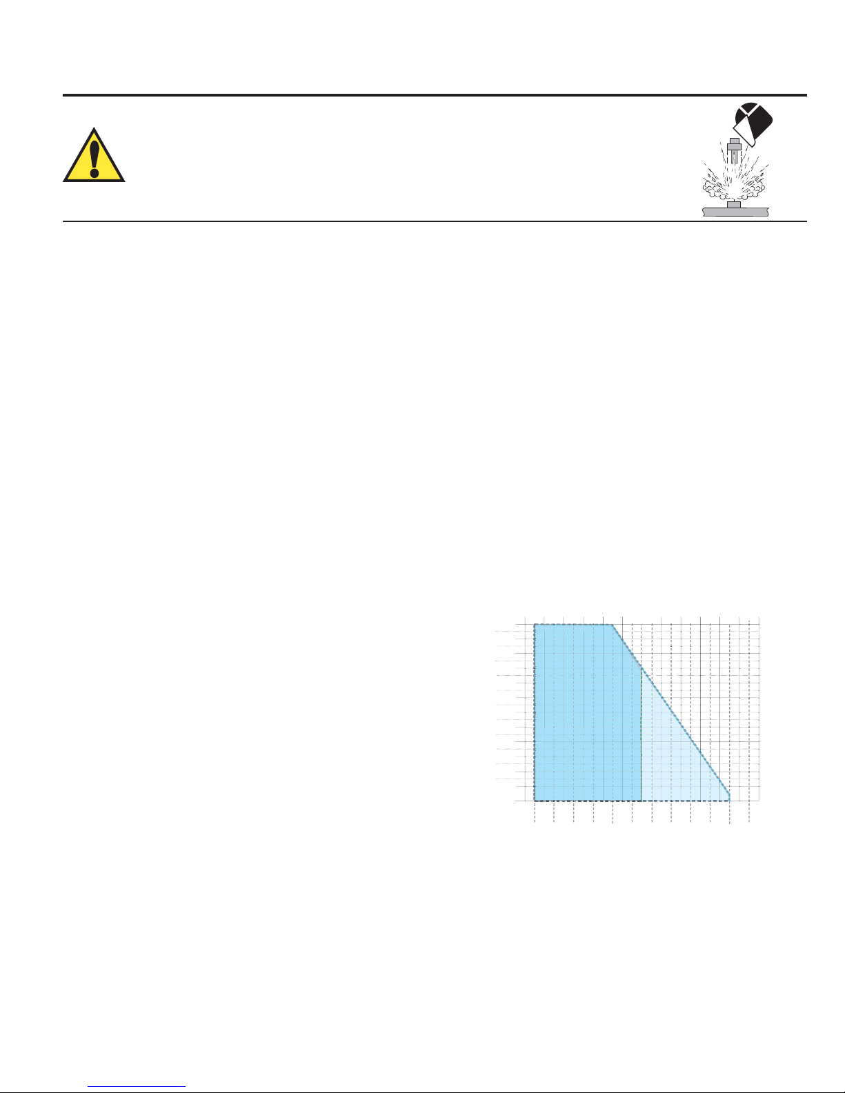
2. Set the 4-20 mA span (4-20 mA output models only)
• Enter the flow rate at 4 mA. (Factory set: 0 m/s)
• Enter the flow rate at 20 mA. (Factory set: 5 m/s)
• When the RESTORE FACTORY SETTINGS button is pressed,
the 20 mA setpoint will be restored to the equivalent of 5 m/s, in
terms of the Flow units and Timebase selected above.
3. Set the Performance Settings to best accomodate the
unique conditions in the pipe.
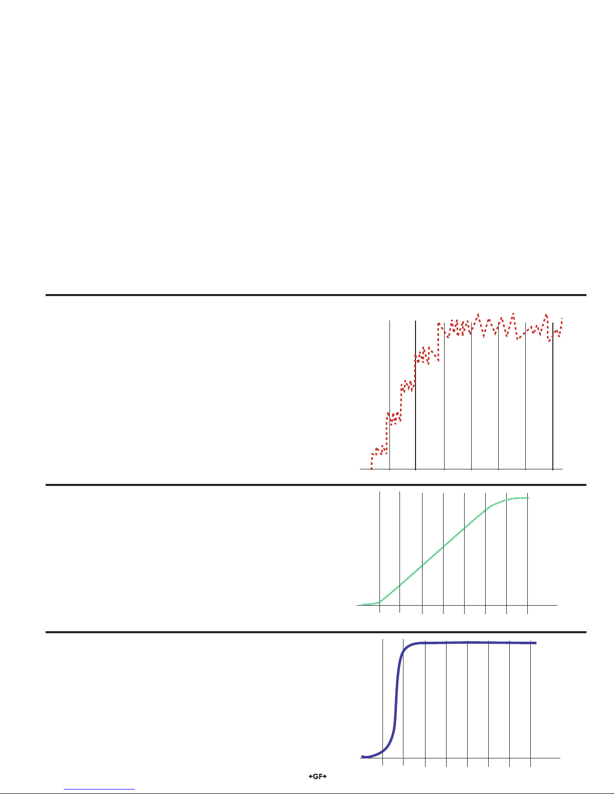
Averaging Time in Seconds (Factory set: 14 seconds)**
• Select the time the Magmeter will use as the averaging
period.
Example: With averaging at 14 seconds, each display is an
average of the previous 14 seconds input.
Use higher averaging times to smooth the display and
current output where the flow in the pipe is erratic.
Quick Response Sensitivity (Factory set: 25% of Max Range, or 2.5 m/s)**
• Set the percentage of change in the flow rate required to
allow the Magmeter to override the AVERAGING and jump
to a new flow rate immediately.
(2552 maximum range is 10 m/s)
A detailed explanation of averaging and sensitivity functions
is provided on the following page.
Noise Rejection Frequency (Factory set: 60 Hz)**
• Select 50 Hz or 60 Hz according to local AC power specifications.
Low Flow Cut-off (Factory set: 0.05 m/s)
• Set the flow rate where all Magmeter outputs will be forced to zero.
(When the flow rate drops below this value, the frequency output will be 0 Hz. and the current output will be 4 mA.)
4. Click "Write Settings to Sensor" at the bottom of the display to download the new settings to the Magmeter.
• To repeat the same settings in another Magmeter, remove 24 VDC Power to the magmeter and connect the second Magmeter.
• Click "Write Settings to Sensor" again.
• Click "Read Sensor Settings" to validate the new settings.
Note: All settings are lost when you exit the program.
Sensor Information
Serial Number, Sensor Type:
• Information for these fields is read from the Magmeter when you press the "Read Sensor Settings" button.
Messages
• Displays messages related to the current selection. Error messages and procedure instructions appear here.
Controls
• Read sensor settings: Read information and setup values from the Magmeter into this setup display.
• Restore factory settings: Restores Loop and Performance settings to original factory values.
Press this button before entering any data into the program if you want to load all factory settings.
• Write settings to sensor: Copies all of the settings in this setup display into the Magmeter.
• Load settings from file: Load a saved meter setup file into the Magmeter Setup Tool.
• Save settings to file: Save a meter setup file on your local hard drive to be used again.
Note: If a Low flow Cutoff or a 4-20 mA field turns
RED, the value entered is outside of the allowable
range. The maximum allowable value will be
automatically loaded.
** SELECT FROM PULL-DOWN MENU ONLY.
Direct text input will not be accepted. Error message
will appear: "Cannot write all settings to sensor."