SAFETY INSTRUCTIONS
1. Depressurize and vent system prior to installation or removal.
2. Con!rm chemical compatibility before use.
3. Do not exceed maximum temperature/pressure speci!cations.
4. Wear safety goggles or faceshield during installation/service.
5. Do not alter product construction.
6. If this equipment is used in a manner not speci!ed by the manufacturer, the protection provided
by the equipment may be impaired.
7. This device is not approved for use or installation in hazardous locations.
Signet 2537 Paddlewheel Flowmeter
3-2537.090 Rev G 9/12 English
English
Specifications
General
Wetted Materials
Model Suffix Sensor Body Rotor Pin O-ring
-P0, -P1 glass-!lled PP PVDF, Black;
optional ETFE
w/ or w/o carbon
!ber reinforced
PTFE sleeve
Titanium FPM
-T0 PVDF, Natural PVDF, Natural;
optional ETFE
w/ or w/o carbon
!ber reinforced
PTFE sleeve
PVDF,
Natural
FPM
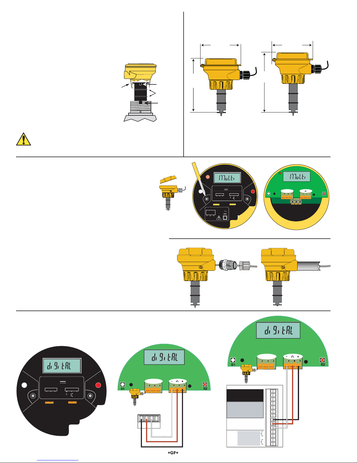
Case: PBT, yellow
Inside Cover: Valox, black
Wiring Ports: ½in. NPT threads; liquid-tight
connector accepts cables 7 to
10 mm OD (0.275 in. to 0.394 in.)
Power Requirements
Multi:
with Dry-Contact Relay: 24 VDC nominal, ±10%, regulated
30 mA max. current
with Solid-State Relay: 5 to 24 VDC nominal, ±10%, regulated
30 mA max. current
Digital (S3L): 5.0 VDC min. to 6.5 VDC max.
30 mA max. current (1.5 mA nominal)
4 to 20 mA: 400 mV max. ripple voltage
30 mA max. current
Reverse Polarity and Short Circuit Protected: Up to 40 V, 1 hour
Over-Voltage Protection: > 40 VDC over 1 hour
Description
The 2537 Paddlewheel Flowmeter Series offer low #ow, low power and high resolution with various output options such as a Volumetric
Pulse, Pulse Divider, Flow Switch, Digital (S3L), or 4 to 20 mA. This unit can be con!gured on-site directly through the built-in user
interface.
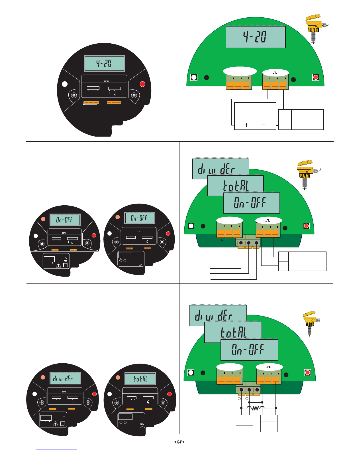
• The 4 to 20 mA model provides a blind current loop output.
• The Digital (S3L) model provides a Digital (S3L) output for use with the Signet 8900 Multi-Parameter Controller or 9900 Transmitter.
• The Multi model uses a single relay (mechanical or solid state) and has three selectable operating modes:
• Divider Mode scales the paddlewheel frequency down to accommodate low frequency input devices.
• Total Mode outputs one pulse per a set volume of #uid.
• Flow Switch Mode uses a single relay for Hi or Lo alarm operation.
A small LCD enables the 2537 to be programmed without any external equipment. During normal operation the display is not visible.
For earlier versions of this sensor, please visit our manual archives at www.gfsignet.com and download the 2537 rev C manual.
Paddlewheel Sensor Performance Specifications
Pipe Size Range: DN15 to DN200 (½in. to 8 in.)
Min. Reynolds Number: 4500
Paddlewheel Frequency: 49 Hz per m/s nominal
(15Hzperft/snominal)
Operating Range: 0.1 m/s to 6 m/s (0.3 ft/s to 20 ft/s)
Linearity: ±1% of max. range @ 25 °C (77 °F)
Repeatability: ±0.5% of max. range @ 25 °C (77 °F)
Electronics Performance Specifications
Input Frequency Range: 1 to 1000 Hz
System Response: 100 ms update rate nominal
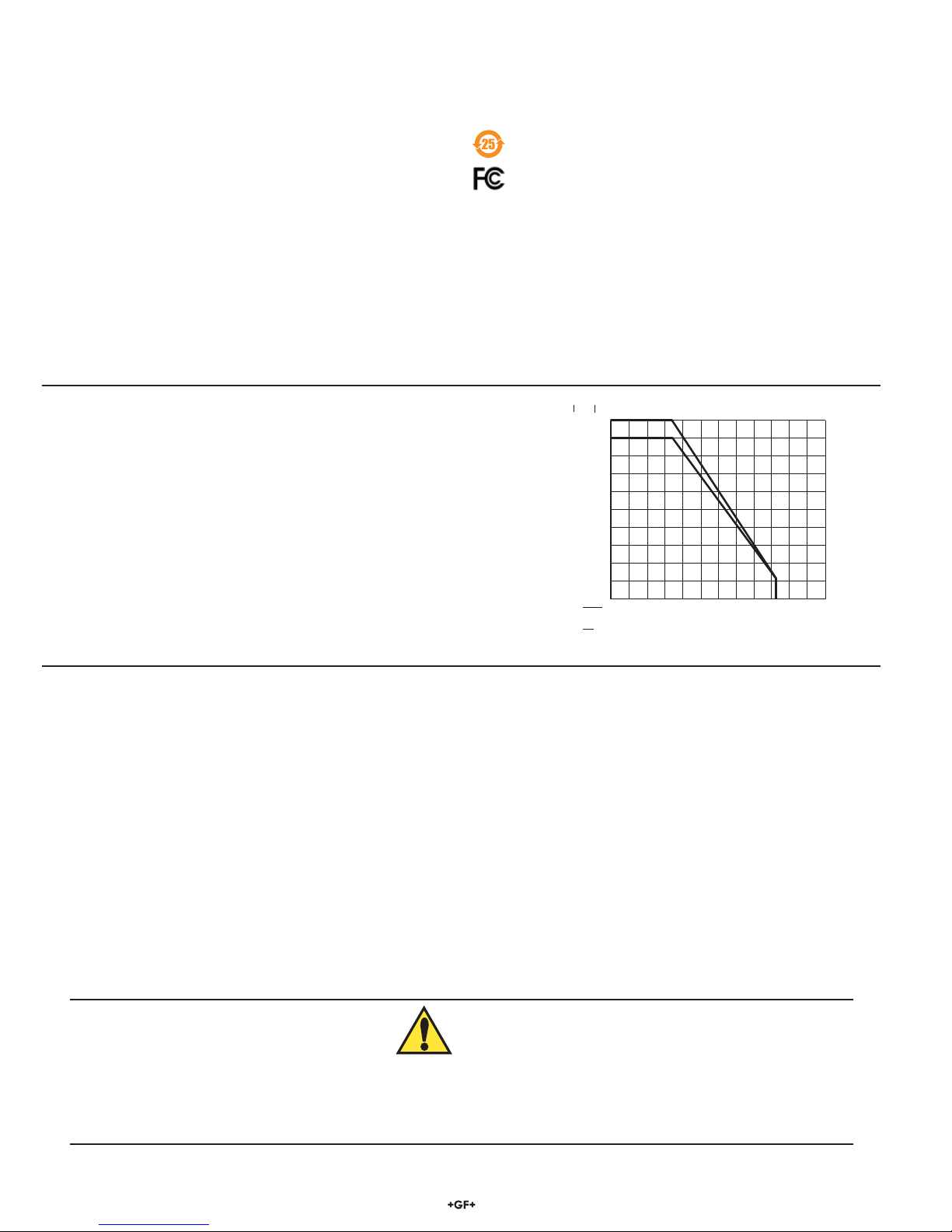
Environmental Requirements
Enclosure Rating: NEMA 4X/IP65
Storage Temperature: -10 to 75 °C (14 to 167 °F)
Ambient Temperature: 0 to 65 °C (32 to 150 °F)
Relative Humidity: 0 to 90% RH, non-condensing
Altitude: 2000 m (6,562 ft)
Pollution Degree: 2
Output Specifications
Signal Averaging: Programmable 0 to 100 seconds
Sensitivity Response: Programmable 0 to 9 scale
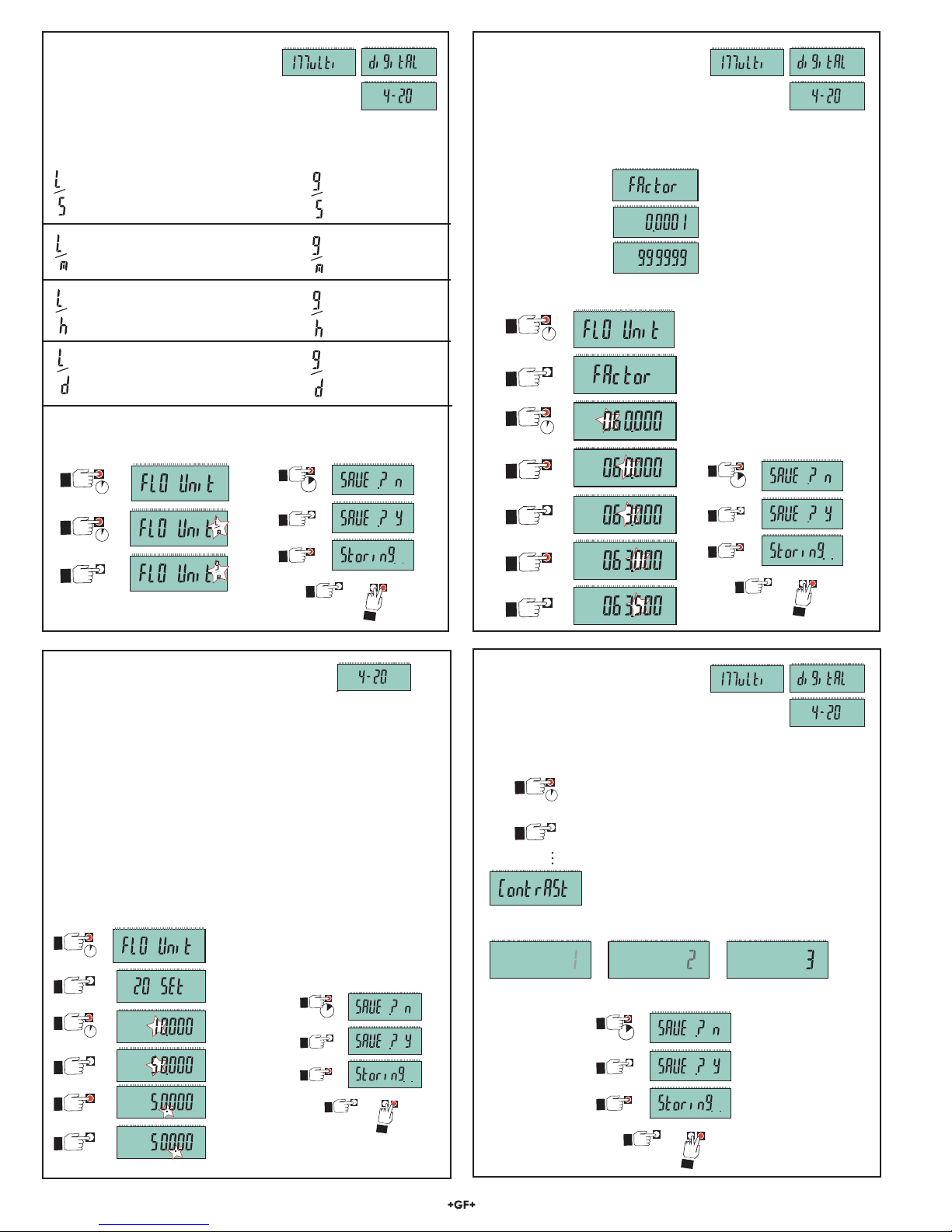
Pulse Divider/Total Pulse Output
Pulse Divider Setting: 1.0000 to 99999
Maximum pulse rate: 300 Hz
Maximum pulse width: 50 ms
*3-2537.090*