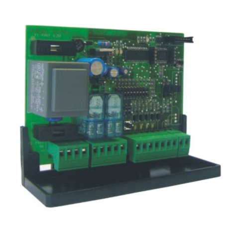
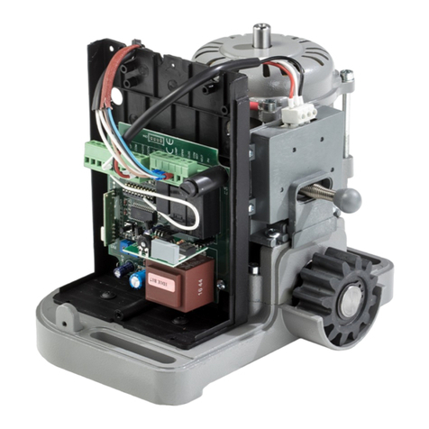
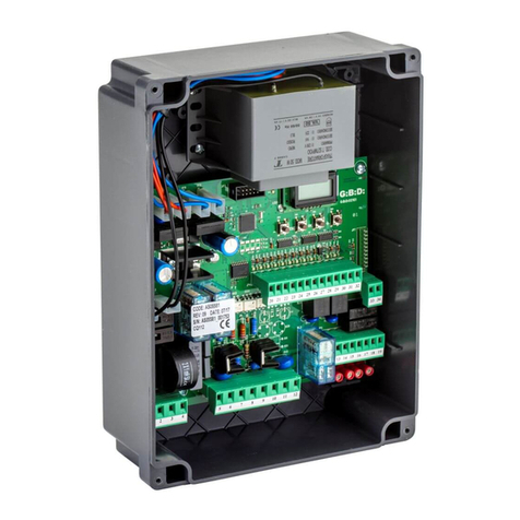
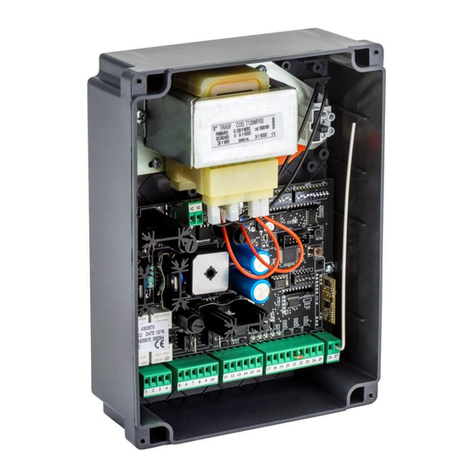
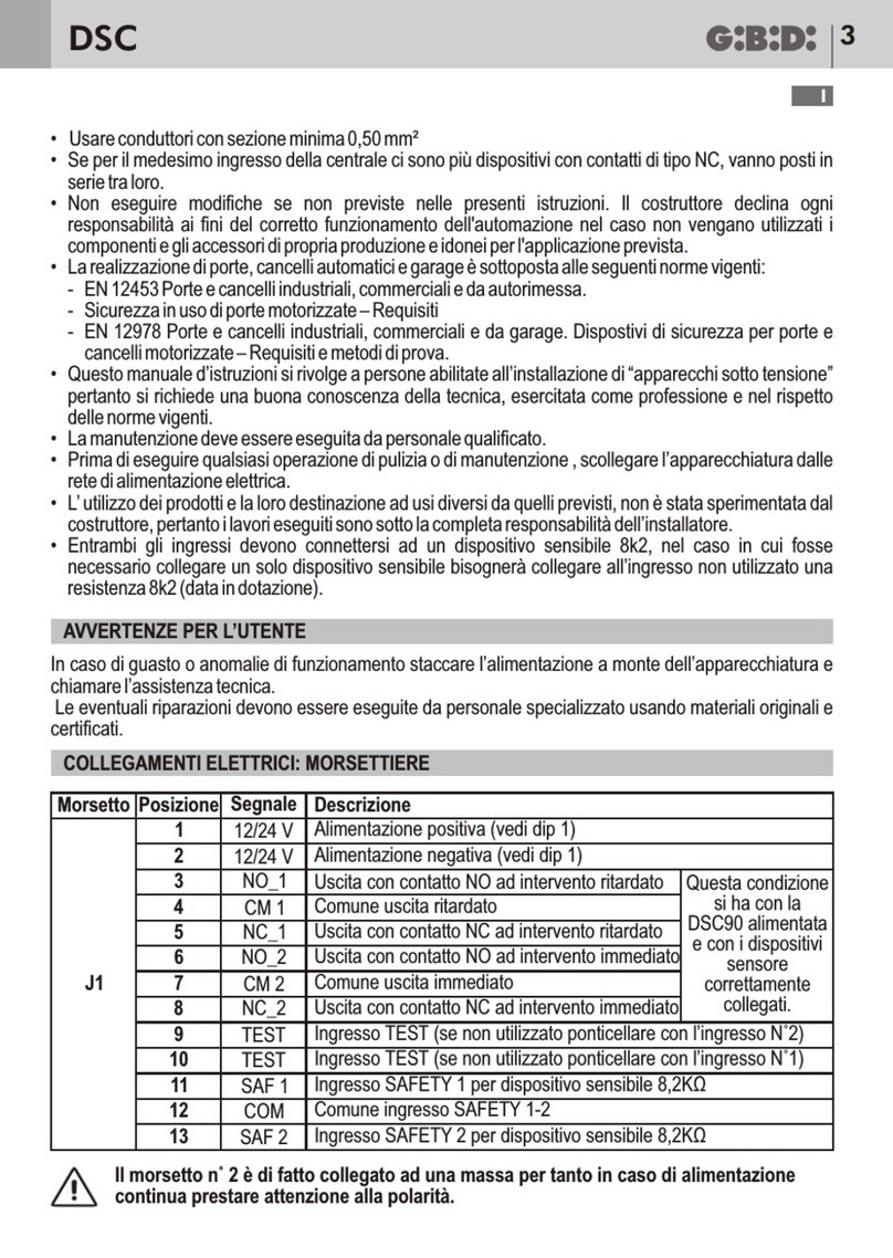
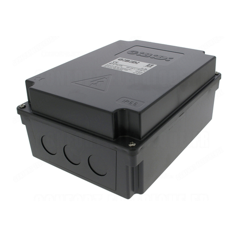
GiBiDi DSC100 Guide

DSC
IT UK FR ES NL
DSC100 - (AS05780) Apparecchiatura elettronica
ISTRUZIONI PER L’INSTALLAZIONE
Electronic control unit
INSTRUCTIONS FOR INSTALLATION
Appareil électronique
INSTRUCTIONS D’INSTALLATION
Equipo electrónico
INSTRUCCIONES DE INSTALACIÓN
Elektronische besturing
GEBRUIKSAANWIJZING VOOR DE INSTALLATIE

DSC100
2
FIG. 1
3
FIG. 2
FIG. 2A
FIG. 2B
FIG. 2C
FIG. 2D
FIG. 2E
1
A
2
C
B
2
B
C
2
3
DSC100 3
Ø8mm MAX
10mm MAX
56
34
12
SC24 SC230
SW1
J3
RL2
RL1
F1
J8
J5
1A
78 9 10 11 12
J2
J9
230Vac - NEUTRAL
N L
230Vac - LINE
10 11 12
J2
10 11 12
J2
FC
COM FC
COM STOP
STOP
NC EM
NO EM
COM EM
L/S
L/S 12/24
L/S 230
LAMP 12/24
LAMP 12/24
LAMP 230
LAMP 230
1
A

DSC100
4
• Prima di procedere con l'installazione bisogna predisporre a monte dell'impianto un interruttore magneto termico o
differenziale con portata massima 10A. L'interruttore deve garantire una separazione omnipolare dei contatti, con
distanza di apertura di almeno 3 mm.
• Per evitare possibili interferenze, differenziare e tenere sempre separati i cavi di potenza (sezione minima 1,5mm²)
dai cavi di segnale (sezione minima 0,5mm²).
• Eseguire i collegamenti facendo riferimento alle tabelle seguenti e alla serigrafia allegata. Fare molta attenzione a
collegare in serie tutti i dispositivi che vanno collegati allo stesso ingresso N.C. (normalmente chiuso) e in parallelo
tutti i dispositivi che condividono lo stesso ingresso N.A. (normalmente aperto). Una errata installazione o un uso
errato del prodotto può compromettere la sicurezza dell'impianto.
• Tutti i materiali presenti nell'imballo non devono essere lasciati alla portata dei bambini in quanto potenziali fonti di
pericolo.
• Il costruttore declina ogni responsabilità ai fini del corretto funzionamento dell'automazione nel caso non vengano
utilizzati i componenti e gli accessori di propria produzione e idonei per l'applicazione prevista.
• Al termine dell'istallazione verificare sempre con attenzione il corretto funzionamento dell'impianto e dei dispositivi
utilizzati.
• Questo manuale d'istruzioni si rivolge a persone abilitate all'installazione di “apparecchi sotto tensione” pertanto si
richiede una buona conoscenza della tecnica, esercitata come professione e nel rispetto delle norme vigenti.
• La manutenzione deve essere eseguita da personale qualificato.
• Prima di eseguire qualsiasi operazione di pulizia o di manutenzione , scollegare l'apparecchiatura dalle rete di
alimentazione elettrica.
• L'apparecchiatura qui descritta deve essere utilizzata solo all'uso per il quale è stata concepita. Verificare lo scopo
dell'utilizzo finale e assicurarsi di prendere tutte le sicurezze necessarie.
• L' utilizzo dei prodotti e la loro destinazione ad usi diversi da quelli previsti non è stata sperimentata dal costruttore,
pertanto i lavori eseguiti sono sotto la completa responsabilità dell'installatore.
• Segnalare l'automazione con targhe di avvertenza che devono essere visibili.
• Avvisare l'utente che bambini o animali non devono giocare o sostare nei pressi del cancello.
• Proteggere adeguatamente i punti di pericolo (per esempio mediante l'uso di una costa sensibile).
DESCRIZIONE DEL PRODOTTO
CARATTERISTICHE TECNICHE / FUNZIONI
AVVERTENZE PER L'INSTALLAZIONE
La scheda elettronica DSC100 può gestire un elettromagnete utilizzato come accessorio esterno su operatori
scorrevoli al fine di rendere l'impianto reversibile o irreversibile.
• Jumper per impostazione tipologia impianto
Possibilità di utilizzare un finecorsa per tenere bloccato il cancello in apertura
Funzionamento automatico all'alimentazione della centrale oppure a seguito di opportuno comando
Possibilità di comando tramite segnale lampeggiatore sia 12/24 Vdc che 230 Vac
•
•
•
IT
APPARECCHIATURA DSC100 / AS05780
Tipo
Alimentazione
Tensione alimentazione elettromagnete
Tensione mantenimento elettromagnete
Potenza elettromagnete
Contatto relè
Temperatura di utilizzo
Scheda gestione elettromagnete
230 Vac
24 Vdc
12 Vdc
50 VA
250 Vac 16 A
-20°C +60°C
DSC100 5
AVVERTENZE PER L'UTENTE
INSTALLAZIONE ELETTROMAGNETE - FIG. 2
In caso di guasto o anomalie di funzionamento staccare l'alimentazione a monte dell'apparecchiatura e chiamare
l'assistenza tecnica. Le eventuali riparazioni devono essere eseguite da personale specializzato usando materiali
originali e certificati.
Il prodotto non deve essere usato da bambini o persone con ridotte capacità fisiche, sensoriali o mentali, oppure
mancanti di esperienza e conoscenza, a meno che non siano stati correttamente istruiti
Non accedere alla scheda per regolazioni e/o manutenzioni
1. Togliere il corpo sblocco dopo aver svitato le 2 viti a brugola. Gli stessi fori M6 servono per il fissaggio
dell'elettromagnete.
2. Fissare la flangia di supporto (1) al corpo riduttore mediante la vite a testa svasata (A).
3. Forare il corpo del riduttore (Ø = 6) in corrispondenza del foro dentro all’asola (2) e far passare i cavi
dell'elettromagnete all'interno del corpo riduttore.
4. Fissare l'elettromagnete (3) alla flangia mediante la vite a testa cilindrica L = 16 mm (B) e al corpo del motoriduttore
mediante la vite a testa cilindrica L = 30 mm (C)
IT
COLLEGAMENTI ELETTRICI: MORSETTIERE
Morsetto Posizione Segnale Descrizione
J9
J5 Vedere NOTA 1
J8
J3
J2
1
2
3
4
5
6
7
8
9
10
11
12
L
N
COM_FC
FC
COM_STOP
STOP
NC_EM
NO_EM
COM_EM
L/S
S12/24
L12/24
L230
Ingresso alimentazione 230 Vac
Comune finecorsa
Ingresso finecorsa
Comune pulsante STOP di emergenza
Ingresso pulsante STOP di emergenza
Contatto NC per collegamento elettromagnete
Contatto NA per collegamento elettromagnete
Comune per collegamento elettromagnete
Comune lampeggiante
Ingresso lampeggiante 12/24 Vdc
Ingresso lampeggiante 230 Vac
FUSIBILI DI PROTEZIONE
Posizione Valore Tipo Descrizione
F1 1 A RAPIDO Protezione scheda
ATTENZIONE: IMPORTANTI ISTRUZIONI DI SICUREZZA.
E' importante per la sicurezza delle persone seguire queste istruzioni.
Conservare il presente libretto di istruzioni.

DSC100
6
IMPOSTAZIONI - JUMPER SW1
IMPOSTAZIONE DI DEFAULT
Jumper
SW1
Posizione
ON
Stato Funzione Descrizione
SW1
ON
OFF
IMPIANTO
IRREVERSIBILE
IMPIANTO
REVERSIBILE
Vedere paragrafo dedicato
FUNZIONAMENTO DEL PRODOTTTO
Collegare l'elettromagnete tra i morsetti 8 e 9. In assenza di alimentazione 230 Vac il cancello è libero di muoversi.
Quando la centrale DSC100 viene alimentata si hanno le seguenti possibilità.
IMPIANTO IRREVERSIBILE (SW1 = ON)
All'alimentazione della centrale DSC100 l'elettromagnete si attiva bloccando il motore e rendendo quindi l'impianto
irreversibile. L'elettromagnete resterà attivo fino a quando sarà presente la tensione di alimentazione centrale.
E' possibile collegare all'ingresso STOP un pulsante con riarmo.
La pressione del tasto STOP disattiverà l'elettromagnete rendendo l'impianto reversibile.
Per riattivare l'elettromagnete sarà necessario riarmare il pulsante STOP.
In questa modalità l'ingresso FC non è attivo
IMPIANTO REVERSIBILE (SW1 = OFF)
E' necessario abilitare la funzione PRELAMPEGGIO sulla centrale che comanda il motoriduttore.
All'alimentazione della centrale DSC100 l'elettromagnete rimane disattivato lasciando l'impianto reversibile.
L'attivazione dell'elettromagnete, con conseguente blocco del motore e impianto irreversibile, si avrà solo in
conseguenza alla presenza del segnale del lampeggiatore proveniente dalla centrale di comando del motoriduttore.
L'elettromagnete rimarrà attivo fin quando sarà presente il segnale del lampeggiatore e si disattiverà 1 s dopo la
scomparsa del segnale.
In questo modo l'elettromagnete si disattiverà sia quando il cancello è in pausa (fase apertura completata) che
quando il cancello è a riposo (fase chiusura completata)
Sarà comunque possibile mantenere il cancello bloccato in apertura e/o chiusura installando un finecorsa e
utilizzando l'ingresso FC. Fare attenzione a fare intervenire il finecorsa prima della fine del moto del cancello.
NOTA 1: Il finecorsa da collegare agli ingressi 3 e 4 NON è il finecorsa che comanda l'arresto del motore.
E' un dispositivo supplementare che si deve attivare prima dell'attivazione del finecorsa che blocca il cancello.
DSC100 7
IT IT
AVVERTENZE: Questo prodotto è stato collaudato in GI.BI.DI. verificando la perfetta corrispondenza delle caratteristiche alle direttive vigenti.
GI.BI.DI. S.r.l. dichiara che i prodotti, a cui questo libretto fa riferimento, sono conformi ai requisiti essenziali delle DIRETTIVE EMC 2004/108/CE
e LVD 2006/95/CE. La dichiarazione completa è disponibile sul sito www.gibidi.com
SMALTIMENTO: GI.BI.DI. consiglia di riciclare i componenti in plastica e di smaltire in appositi centri abilitati i componenti elettronici evitando
di contaminare l'ambiente con sostanze inquinanti.
LEGGERE ATTENTAMENTE QUESTO MANUALE PRIMA DI PROCEDERE ALL’INSTALLAZIONE.
Grazie per avere scelto GIBIDI.
Dichiarazione di conformità CE
Il fabbricante:
GI.BI.DI.
Via Abetone Brennero, 177/B,
46025 Poggio Rusco (MN) ITALY
dichiara che i prodotti:
APPARECCHIATURA ELETTRONICA DSC100
sono conformi alle seguenti Direttive CEE:
• Direttiva LVD 2006/95/CE e successive modifiche;
• Direttiva EMC 2004/108/CE e successive modifiche;
e che sono state applicate le seguenti norme armonizzate:
• EN60335-1,
• EN61000-6-2, EN61000-6-3
Data 24/09/2018
S.r.l.
Il Rappresentante Legale
Michele Prandi

DSC100
8
UK UK
PRODUCT DESCRIPTION
FEATURES / FUNCTION
The electronic board AS05780 can manage an electromagnet used as accessory on a sliding gate to make the
system reversible or irreversible.
• Jumper to select installation type.
Possibility of using a limit switch to keep the gate locked in opening.
Automatic functioning at the power on or after a proper command.
Possibility of using the flashing light signal 12/24 Vdc or 230 Vac to activate the functioning cycle
•
•
•
CONTROL UNIT DSC100 / AS05780
Type
Power supply
Electromagnet power supply
Electromagnet voltage maintenance
Electromagnet power
Relay contact
Operating temperature
Electronic board for electromagnet management
230 Vac, single-phase, 50/60 Hz
24 Vdc
12 Vdc
50 VA
250 Vac 16 A
-20°C +60°C
INSTALLATION WARNINGS
• Before proceeding with the installation, fit a magnetothermal or differential switch with a maximum capacity of 10°
upstream of the system. The switch must guarantee omnipolar separation of the contacts with an opening distance
of at least 3 mm.
To prevent possible interference, differenziate and always keep the power cables (minimum cross-section
1.5 mm²) separate from the signal cables (minimum cross-section 0,5mm²).
Make the connections referring to the following tables and to the attached silkscreen. Be extremely careful to
connect in series all the devices that are connected to the same N.C. (normally closed) input, and in parallel all the
devices that share the same N.O. (normally open) input. Incorrect installation or improper use of the product may
compromise system safety.
Keep all the materials container in the packaging away from children since they pose a potential risk.
The manufacturer declines all responsibility for improper functioning of the automated device if the original
components and accessories suitable for the specific application are not used.
After installation, always check carefully proper functioning of the system and the devices used.
This instruction manual addresses people qualified for installation of “live equipment”. Therefore, good technical
knowledge and professional practice in compliance with the regulations in force are required.
Maintenance must be carried out by qualified personnel.
Before carrying out any cleaning or maintenance operation, disconnect the control unit from the mains.
This control unit may only be used for the purpose for which it was designed. Check the aim of the final use and
make sure that all safety measures are taken.
Use of the product for purposes different from the intended use has not been tested by the manufacturer, therefore
any work is carried out on full responsibility of the installer.
Mark the automated device with visibile warning plates.
Warn the user that children or animals may not play or stand around near the gate.
Appropiately protect the dangerous points (for example, using a sensitive frame).
•
•
•
•
•
•
•
•
•
•
•
•
•
DSC100 9
WARNINGS FOR THE USER
ELECTROMAGNET INSTALLATION - FIG. 2
In the event of an operating fault or failure, cut the power upstream of the control unit and call Technical Service.
Periodically check functioning of the safety devices. Any repairs must be carried out by specialised personnel using
original and certified materials. The appliance is not to be used by children or people with reduced physical, sensory
or mental capabilities, or lack of experience and knowledge, unless they have been given supervision or instruction.
Do not access the control board for settings and / or maintenance.
1. Remove the unlocking body after having unscrewed the 2 Allen screws. The same holes M6 are used to fix the
electromagnet.
2. Fix the support flange (1) to the gearmotor body by means of the countersunk head screw (A).
3. Drill the gearmotor body (Ø = 6) in correspondence to the hole inside the slotted hole (2) and run the electromagnet
cables through the gearmotor body.
4. Fix the electromagnet (3) to the flange with the cylyindrical head screw L = 16 mm (B) and to the gearmotor body by
means of the cylindrical head screw L = 30 mm (C)
ELECTRICAL CONNECTIONS: TERMINAL BLOCKS
Terminal Position Signal Description
J9
J5 See NOTE 1
J8
J3
J2
1
2
3
4
5
6
7
8
9
10
11
12
L
N
COM_FC
FC
COM_STOP
STOP
NC_EM
NO_EM
COM_EM
L/S
S12/24
L12/24
L230
Power input 230 Vac
Power input 230 Vac
Common limit switch
Limit switch input
Common emergency STOP push button
Emergency STOP push button input
NC contact for electromagnet connection
NO contact for electromagnet connection
Common contact for electromagnet connection
Common flashing light
Flashing light input 12/24 Vdc
Flashing light input 230 Vac
PROTECTION FUSES
Position Value Type Description
F1 1 A FAST Electronic board protection
WARNING: IMPORTANT SAFETY INSTRUCTIONS
It is very important to follow the present instructions for your own safety.
Please keep this manual

DSC100 11
CE Declaration of conformity
The manufacturer:
GI.BI.DI. S.r.l.
Via Abetone Brennero, 177/B,
46025 Poggio Rusco (MN) ITALY
declares that the products:
ELECTRONIC CONTROL UNIT DSC100
are in conformity with the following CEE Directives:
•
• EMC Directive 2004/108/CE and subsequent amendments;
and that the following harmonised standards have been applied:
• EN60335-1,
• EN61000-6-2, EN61000-6-3
Date 24/09/2018
LVD Directive 2006/95/CE and subsequent amendments;
The legal Representative
Michele Prandi
SETTINGS - JUMPER SW1
DEFAULT SETTINGS
Jumper
SW1
Position
ON
State Function Description
SW1
ON
OFF
IRREVERSIBLE
SYSTEM
REVERSIBLE
SYSTEM
See proper section
See proper section
FUNCTIONING
Connect the electromagnet between terminals 8 and 9. In the absence of power supply 230 Vac the gate is free to
move. When the control unit AS05780 is powered you have the following options.
IRREVERSIBLE SYSTEM (SW1 = ON)
Powering the control unit AS05780 the electromagnet activates blocking the gearmotor and therefore making the
system irreversible. The electromagnet will remain active until the power supply of the control unit will be present.
You can connect to the STOP input a push button with reset. By pushing the STOP button you will turn off
the electromagnet making the system reversible. To reactivate the electromagnet will be necessary to reset the
STOP button.
In this mode the FC input is not active
REVERSIBLE SYSTEM (SW1 = OFF)
It is necessary to enable the PRE-FLASHING function on the control board of the gearmotor.
Powering the control unit AS05780 the electromagnet remains not active leaving the system reversible .
The electromagnet activation, with locking of the gearmotor and irreversible system, will happen only by a
consequence of the presence of the flashing light signal of the gearmotor control unit.
The electromagnet will remain active until the flashing light signal will be present and it will turn off 1 s after the
disappearance of the signal.
In this way the electromagnet is deactivated both when the gate is in pause (opening phase completed) and the gate
is in sleep (closing phase completed)
You can always keep the gate blocked in open and/or closed position by using a limt switch wired to the FC input.
Be careful that the limit switch must active before the end of the gate movement.
NOTE 1: The limit switch wired to the input 3 and 4 is NOT the limit switch for stopping the motor. It's simply an
auxiliary device which must be activated before the activation of the limit switch which cause the gate movement to
stop.
DSC100
10
UK UK
WARNINGS: This product has been tested in GI.BI.DI. verifying the perfect correspondence of the characteristics to the current directive.
GI.BI.DI. S.r.l. declares that the products to which this handbook refers comply with the essential requirements of the following DIRECTIVES
EMC 2004/108/CE - LVD 2006/95/CE. The entire declaration is available at www.gibidi.com.
DISPOSAL: GI.BI.DI. advises recycling the plastic components and to dispose of them at special authorised centres for electronic
components thus protecting the environment from polluting substances.
PLEASE READ CAREFULLY THIS MANUAL BEFORE PROCEEDING WITH THE INSTALLATION.
Thank you for choosing GI.BI.DI.

DSC100
12
FR FR
DESCRIPTION DU PRODUIT
FEATURES / FUNCTION
La fiche électronique AS05780 peut gérer un électroaimant utilisé comme accessoire extérieur sur opérateurs
coulissants à fin de rendre l'installation réversible ou irréversible.
• Jumper pour paramétrer typologie installation.
Possibilité d'utiliser un fin de course pour tenir bloqué le portail en ouverture.
Fonctionnement automatique à l'alimentation de la platine ou après commande adéquate.
Possibilité de commande par signal clignoteur soit 12/24 Vdc que 230 Vac
•
•
•
PLATINE COMMANDE DSC100 / AS05780
Type
Alimentation
Tension alimentation électroaimant
Tension entretien électroaimant
Puissance électroaimant
Contact relais
Température de service
Fiche gestion électroaimant
230 Vac
24 Vdc
12 Vdc
50 VA
250 Vac 16 A
-20°C +60°C
CONSIGNES POUR L'INSTALLATION
• Avant d'effectuer la mise en place, il faut prévoir en amont de l'installation un interrupteur magnétique thermique ou
différentiel ayant une capacité maximum de 10A. L'interrupteur doit assurer une séparation omnipolaire des
contacts, avec une distance d'ouverture d'au moins 3 mm.
Pour éviter de possibles interférences, il faut différencier et tenir toujours séparés les câbles de puissance (section
min. 1,5mm²) des câbles de signal (section min. 0,5mm²).
Il faut effectuer les connexions en se référant aux tableaux suivants et à la sérigraphie jointe. Il faut faire
particulièrement attention à raccorder en série tous les dispositifs qui doivent être connectés à la même entrée N.C.
(normalement fermé) et en parallèle tous les dispositifs qui partagent la même entrée N.A. (normalement ouvert).
Une mauvaise installation ou une mauvaise utilisation du produit peut compromettre la sécurité de l'installation.
Tous les matériaux présents dans l'emballage ne doivent pas être laissés à la portée des enfants, car ils peuvent
être dangereux.
Le constructeur décline toute responsabilité, quant au bon fonctionnement de l'automation, en cas d'utilisation de
composants et d'accessoires n'étant pas de sa production et inappropriés à l'utilisation prévue.
Après la mise en place, il faut toujours contrôler avec attention le bon fonctionnement de l'installation et des
dispositifs utilisés.
Ce manuel d'instructions s'adresse aux personnes autorisées à effectuer la mise en place d'“appareils sous
tension”. Il faut donc avoir une bonne connaissance de la technique, exercée comme profession et conformément
aux réglementations en vigueur.
La maintenance doit être effectuée par un personnel qualifié.
Avant d'effectuer toute opération de nettoyage ou de maintenance, il faut débrancher l'appareil des réseaux
d'alimentation électrique.
L'appareil ici décrit doit être utilisé uniquement pour l'emploi pour le quel il a été conçu. Vérifier le bût de l'utilisation
finale et s'assurer de prendre toutes les sécurités nécessaires.
L'utilisation des produits et leur destination à des usages différents de ceux prévus n'a pas été expérimentée par le
constructeur, donc les travaux exécutés sont sous l'entière responsabilité de l'installateur.
• Il faut signaler l'automation à l'aide de plaques de mise en garde, qui doivent être visibles.
• Il faut avertir l'utilisateur qu'il est interdit que des enfants ou des animaux ne jouent ou ne stationnent à proximité du
portail.
• Il faut protéger comme il se doit les points à risque (par exemple à l'aide d'un bord sensible).
•
•
•
•
•
•
•
•
•
•
DSC100 13
MISES EN GARDE POUR L'UTILISATEUR
INSTALLATION DE L'ELECTRO-AIMANT - FIG. 2
En cas de pannes ou d'anomalies de fonctionnement, il faut couper l'alimentation en amont de l'appareil et appeler
l'assistance technique. Les éventuelles réparations doivent être exécutées par un personnel spécialisé qui utilise
des matériels d'origine et certifiés. Le produit ne doit pas être utilisé par enfants ou personnes avec réduites
capacités physiques, sensoriales ou mentales, ou sans expérience et connaissance, à moins qu'elles ne soient pas
correctement instruites. Ne pas accéder à la fiche pour régulations et / ou maintenances.
1. Déposer le dispositif de déblocage après avoir dévissé les 2 vis à six pan. Les memes trous M6 servent à la fixation
de l'èlectro-aimant.
2. Fixer le bride de support (1) au corps du réducteur à l'aide de la vis à tête conique (A).
3. Percer le corps du réducteur (Ø = 6) en correspondance du trou de la boucle (2) et faire passer les câbles de
l'électro-aimant à l'intérieur du réducteur.
4. Fixer l'électro-aimant (3) à la bride à l'aide de vis à tête cylindrique L = 16 mm (B) et au corps du motoréducteur à
l'aide de vis à tête cylindrique L = 30 mm (C).
BRANCHEMENTS ELECTRIQUES: BORNIERS
Borne Position Signal Description
J9
J5 Voir NOTE 1
J8
J3
J2
1
2
3
4
5
6
7
8
9
10
11
12
L
N
COM_FC
FC
COM_STOP
STOP
NC_EM
NO_EM
COM_EM
L/S
S12/24
L12/24
L230
Entrée alimentation 230 Vac
Commun fin de corse
Entrée fin de corse
Commun touche STOP d'émergence
Entrée touche STOP d'émergence
Contact NC pour branchement électroaimant
Contact NA pour branchement électroaimant
Commun pour branchement électroaimant
Commun clignoteur
Entrée clignoteur 12/24 Vdc
Entrée clignoteur 230 Vac
FUSIBLES DE PROTECTION
Position Valeur Type Description
F1 1 A RAPIDE Protection fiche
ATTENTION: IMPORTANTES INSTRUCTIONS DE SECURITE
C'est important pour la sécurité des personnes de suivre ces instructions-ci.
Garder le présent manuel d'instructions.

DSC100
14
FR FR
PARAMETRAGES - JUMPER SW1
PARAMETRAGES PAS DEFAUT
Jumper
SW1
Position
ON
Etat Fonction Description
SW1
ON
OFF
INSTALLATION
IRREVERSIBLE
INSTALLATION
REVERSIBLE
Voir paragraphe de référence
FONCTIONNEMENT DU PRODUIT
Brancher l'électroaimant entre les bornes 8 et 9. En absence d'alimentation 230 Vac le portail est libre de se mouvoir.
Quand la platine AS05780 est alimentée, on a les suivantes possibilités.
INSTALLATION IRREVERSIBLE (SW1 = ON)
A l'alimentation de la platine AS05780, l'électroaimant s'active bloquant le moteur et rendant donc l'installation
irréversible. L'électroaimant restera actif jusqu'à quand la tension d'alimentation platine sera présente.
C'est possible brancher à l'entrée STOP une touche avec réarmement. La pression de la touche STOP désactivera
l'électroaimant, rendant l'installation réversible. Pour réactiver l'électroaimant il faudra réarmer la touche STOP.
Dans cette modalité l'entrée FC n'est pas active
INSTALLATION REVERSIBLE (SW1 = OFF)
Il faut habiliter la fonction PRECLIGNOTEMENT sur la platine qui commande le motoréducteur.
A l'alimentation de la platine AS05780 l'électroaimant reste désactivé laissant l'installation réversible.
L'activation de l'électroaimant, avec conséquent blocage du moteur et installation irréversible, aura lieu seulement
en présence du signal du clignoteur provenant de la platine de commande du motoréducteur.
L'électroaimant restera actif jusqu'à quand le signal du clignoteur sera présent et se désactivera 1 s après la
disparition du signal.
De cette façon l'électroaimant se désactivera soit quand le portail est en pause (phase ouverture complétée) que
quand le portail est au repos (phase fermeture complétée)
De toute façon il sera possible de maintenir le portail bloqué en ouverture ou fermeture installant un fin de course et
utilisant l'entrée FC. Prester attention à faire intervenir le fin de course avant de la fin du mouvement du portail.
NOTE 1: Le fin de course à brancher aux entrées 3 et 4 N'est pas le fin de course qui commande l'arrêt du moteur.
C'est un dispositif supplémentaire qu'on doit activer avant de l'activation du fin de course qui bloque le portail
DSC100 15
Déclaration de conformité CE
La société:
Via Abetone Brennero, 177/B,
46025 Poggio Rusco (MN) ITALY
déclare que les produits:
APPAREIL ÉLECTRONIQUE DSC100
sont en conformité avec les exigences des Directives CEE:
•
• Directive EMC 2004/108/CE et ses modifications;
et que les normes harmonisées suivantes ont été appliquées:
• EN60335-1
• EN61000-6-2, EN61000-6-3
Date 24/09/2018
GI.BI.DI. S.r.l.
Directive LVD 2006/95/CE et ses modifications;
Le Représentant Légal
Michele Prandi
AVERTISSEMENT: Ce produit a été testé chez GI.BI.DI. afin de contrôler la correspondance parfaite des caractéristiques avec les règles en vigueur.
GI.BI.DI. S.r.l. déclare que les produits, auxquels se réfère la notice, sont conformes aux conditions essentielles requises par les
DIRECTIVES suivantes EMC 2004/108/CE - LVD 2006/95/CE. La déclaration complète est disponible sur le site www.gibidi.com.
ELIMINATION : GI.BI.DI. conseille de recycler les composants en plastique et de remettre les composants électroniques à des centres
spécialisés pour éviter de polluer l'environnement avec des substances polluantes.
NOUS VOUS PRIONS DE BIEN VOULOIR LIRE ATTENTIVEMENT CE MANUEL AVANT DE PROCÉDER À L’INSTALLATION.
Merci d’avoir choisi GI.BI.DI.

DSC100
16
ES ES
DESCRIPCION DEL PRODUCTO
CARACTERISTICAS TECNICAS / FUNCIONES
La tarjeta electrónica AS05780 puede gestionar un electroimán utilizado como accesorio externo sobre operadores
de corredera, para que la instalación se haga reversible o irreversible.
• Jumper para configuración tipología instalación.
Posibilidad de utilizar un final de carrera para bloquear la cancela en abertura.
Funcionamiento automático a la alimentación de la central o después de oportuno mando.
Posibilidad de mando por señal destellador tanto 12/24 Vdc como 230 Vac.
•
•
•
CENTRAL DE MANDO DSC100 / AS05780
Tipo
Alimentación
Tensión alimentación electroimán
Tensión mantenimiento electroimán
Potencia electroimán
Contacto relé
Temperatura de utilización
Tarjeta gestión electroimán
230 Vac
24 Vdc
12 Vdc
50 VA
250 Vac 16 A
-20°C +60°C
ADVERTENCIAS PARA LA INSTALACION
• Antes de proceder con la instalación, hay que preparar aguas arriba de la instalación un interruptor magneto térmico o
diferencial con capacidad máxima 10A. El interruptor debe garantizar una separación omnipolar de los contactos, con
distancia de abertura de por lo menos 3 mm.
Para evitar posibles interferencias, distinguir y mantener siempre separados los cables de potencia (sección mínima
1,5mm²) de los cables de señal (sección mínima 0,5mm²).
Realizar las conexiones consultando las siguientes tablas y la serigrafía adjunta. Prestar suma atención a conectar en
serie todos los dispositivos que comparten la misma entrada N.C. (normalmente cerrada) y en paralelo todos los
dispositivos que comparten la misma entrada N.A. (normalmente abierta). Una incorrecta instalación o utilización del
producto puede afectar la seguridad de la instalación.
Todo material presente en el embalaje debe mantenerse fuera del alcance de los niños, ya que consistuye una
posible fuente de peligro.
El fabricante declina toda responsabilidad relativa al funcionamiento correcto de la automación si no se utilizan los
componentes y accesorios de propia producción e idóneos para la aplicación prevista.
Al terminar la instalación, comprobar siempre con atención el correcto funcionamiento del equipo y de los dispositivos
utilizados.
Este manual de instrucciones está destinado a personas habilitadas a la instalación de “equipos bajo tensión”, por lo
tanto se requiere un buen conocimiento técnico, ejercido como profesión y respetando las normas vigentes.
El mantenimiento debe ser realizado por personal capacitado
Antes de realizar cualquier operación de limpieza o mantenimiento, desconectar el equipo de la red de alimentación
eléctrica.
El equipo aquí descrito debe ser utilizado sólo por los fines previstos. Verificar el fin de la utilización final y asegurarse
de tomar todas las seguridades necesarias.
El uso de los productos y su destinación a usos diferentes de los previstos, no han sido experimentados por el
fabricante, por lo que los trabajos realizados quedan bajo la completa responsabilidad del instalador.
• Señalar la automación con placas de advertencia que deben ser visibles.
• Avisar al usuario que está prohibido que niños o animales jueguen o se detengan en los alrededores de la cancela.
• Proteger adecuadamente los puntos peligrosos (por ejemplo usando una banda sensible).
•
•
•
•
•
•
•
•
•
•
DSC100 17
ADVERTENCIAS PARA EL USUARIO
INSTALACIÓN DEL ELECTROIMÁN - FIG. 2
En caso de averías o anomalías de funcionamiento, desconectar la alimentación aguas arriba del equipo y llamar la
asistencia técnica. Las eventuales reparaciones deben ser realizadas por personal especializado y usando
materiales originales y certificados. El producto no debe ser utilizado por niños o personas con reducidas
capacidades físicas, sensoriales o mentales, o sin experiencia y conocimiento, a menos que no hayan sido
correctamente instruidas. No acceder a la ficha para regulaciones y/o mantenimiento.
1. Quitar el cuerpo de desbloqueo tras haber desenroscado los 2 tornillos allen. Los mismos orificios M6 sirven para
sujetar el electroimán.
2. Sujetar l abrida de soporte (1) al cuerpo del reductor mediante el tornillo de cabeze avellanada (A).
3. Perforar el cuerpo del reductor (Ø = 6) en correspondencia del orificio del ojal (2) y hacer pasar los cables del
electroimán al interior del cuerpo reductor.
4. Sujetar el electroimán (3) a al brida mediante el tornillo de cabeza cilíndrica L = 16 mm (B) y al cuerpo del
motorreductor mediante el tornillo de cabeza cilíndrica L = 30 mm (C).
CONEXIONES ELECTRICAS: TABLEROS DE BORNES
Borne Posición Señal Descripción
J9
J5 Ver NOTA 1
J8
J3
J2
1
2
3
4
5
6
7
8
9
10
11
12
L
N
COM_FC
FC
COM_STOP
STOP
NC_EM
NO_EM
COM_EM
L/S
S12/24
L12/24
L230
Entrada alimentación 230 Vac
Común final de carrera
Entrada final de carrera
Común tecla STOP de emergencia
Entrada tecla STOP de emergencia
Contacto NC para conexión electroimán
Contacto NA para conexión electroimán
Común para conexión electroimán
Común destellador
Entrada destellador 12/24 Vdc
Entrada destellador 230 Vac
FUSIBILES DE PROTECCION
Posición Valor Tipo Descripción
F1 1 A RAPIDO Protección tarjeta
CUIDADO: IMPORTANTES INSTRUCCIONES DE SEGURIDAD
Es importante por la seguridad de las personas seguir estas instrucciones.
Conservar el presente manual de instrucciones.

DSC100
18
ES ES
CONFIGURACIONES - JUMPER SW1
CONFIGURACION DE DEFAULT
Jumper
SW1
Posición
ON
Estado Función Descripción
SW1
ON
OFF
INSTALACION
IRREVERSIBLE
INSTALACION
REVERSIBLE
Ver párrafo dedicado
FUNCIONAMIENTO DEL PRODUCTO
Conectar el electroimán entre los bornes 8 y 9. En absencia de alimentación 230 Vac la cancela es libre de moverse.
Cuando la central AS05780 es alimentada hay las siguientes posibilidades.
INSTALACION IRREVERSIBLE (SW1 = ON)
A la alimentación de la central AS05780 el electroimán se activa bloqueando el motor y haciendo así la instalación
irreversible. El electroimán quedará activo hasta cuando será presente la tensión de alimentación central.
Es posible conectar a la entrada STOP una tecla que se pueda rearmar. La presión de la tecla STOP desactivará el
electroimán haciendo la instalación reversible. Para reactivar el electroimán será necesario rearmar la tecla STOP.
En esta modalidad la entrada FC no es activa
INSTALACION REVERSIBLE (SW1 = OFF)
Es necesario activar la función PREDESTELLO en la central que manda el motoreductor.
A la alimentación de la central AS05780 el electroimán queda desactivado dejando la instalación reversible.
La activación del electroimán, con consiguiente bloqueo del motor e instalación irreversible, se verificará sólo en
presencia del señal del destellador proveniente de la central de mando del motoreductor.
El electroimán quedará activo hasta cuando será presente el señal del destellador y se desactivará 1 s después de la
desaparición del señal.
De esta manera el electroimán se desactivará tanto cuando la cancela está en pausa (fase abertura completada)
como cuando la cancela está en reposo (fase cierre completada)
De todas formas será posible mantener la cancela bloqueada en abertura y cierre, instalando un final de carrera y
utilizando la entrada FC. Prestar atención a hacer intervenir el final de carrera antes del final del movimiento de la
cancela.
NOTA 1: El final de carrera que debe ser conectado a las entradas 3 y 4 NO es el final de carrera que manda la
parada del motor. Es un dispositivo suplementario que se debe activar antes de la activación del final de carrera que
bloquea la cancela.
DSC100 19
Declaración de conformidad CE
El fabricante:
Via Abetone Brennero, 177/B,
46025 Poggio Rusco (MN) ITALY
declara que los productos:
EQUIPO ELECTRÓNICO DSC100
cumplen la siguiente Directiva CEE:
•
•
y que se han aplicado las siguientes normas armonizadas :
• EN60335-1
• EN61000-6-2, EN61000-6-3
Fecha 24/09/2018
GI.BI.DI. S.r.l.
Directiva LVD 2006/95/CE y modificaciones sucesivas;
Directiva EMC 2004/108/CE y modificaciones sucesivas;
El Representante Legal
Michele Prandi
ADVERTENCIAS: Este producto ha sido ensayado en GI.BI.DI. averiguando la perfecta correspondencia de las características a las normas vigentes.
GI.BI.DI. S.r.l. declara que los productos referidos en este folleto cumplen con los requisitos esenciales de las DIRECTIVAS siguientes
EMC 2004/108/CE - LVD 2006/95/CE. La declaración completa está disponible en el sitio de internet www.gibidi.com .
ELIMINACION: GI.BI.DI. aconseja reciclar los componentes de plástico y llevar los componentes electrónicos a los centros de recogida
correspondientes evitando de esta manera la contaminación ambiental con sustancias perjudiciales.
POR FAVOR LEER CON ATENCIÓN ESTE MANUAL ANTES DE PROCEDER CON LA INSTALACIÓN.
Gracias por haber elegido GI.BI.DI.

DSC100
20
NL NL
DSC100 21
ŸAlvorens met de installatie te beginnen, moet u een thermomagnetische schakelaar of een differentieelschakelaar met
een maximale stroomsterkte van 10A stroomopwaarts van de installatie plaatsen. De schakelaar moet een omnipolaire
onderbreking van de contacten waarborgen, met openingsafstand van minstens 3 mm.
ŸDifferentieer en houd de vermogenkabels (met minimumdoorsnede van 1,5 mm²) altijd gescheiden van de
signaalkabels (met minimumdoorsnede van 0,5 mm²) om eventuele interferenties te vermijden.
ŸVoer de verschillende aansluitingen uit en raadpleeg hiervoor de volgende tabellen en de bijgevoegde zeefdruk. Let er
in het bijzonder op dat alle voorzieningen die met dezelfde N.C. (normaal gesloten) ingang in serie verbonden moeten
worden, en dat alle voorzieningen die dezelfde N.O (normaal open) ingang delen in parallel worden aangesloten.
ŸEen verkeerde installatie of een verkeerd gebruik van het product kan de veiligheid van het systeem in gevaar brengen.
ŸAlle verpakkingsmaterialen moeten vanwege het mogelijke gevaar buiten het bereik van kinderen worden
gehouden.
ŸDe fabrikant wijst elke verantwoordelijkheid af voor een niet correcte werking van de automatisatie indien er geen
originele onderdelen en toebehoren worden gebruikt die geschikt zijn voor de voorziene toepassing.
ŸNa de installatie moet u steeds grondig controleren of zowel het systeem als de gebruikte voorzieningen correct
werken.
ŸDeze handleiding richt zich tot personen die bevoegd zijn om "apparaten onder spanning" te installeren, en
vandaar dat een goede kennis van de techniek is vereist. De installatie moet uitgevoerd worden door vakmensen
die de geldende voorschriften in acht nemen.
ŸHet onderhoud moet uitgevoerd worden door gekwalificeerd personeel.
ŸAlvorens reiniging- of onderhoudswerkzaamheden uit te voeren, moet de apparatuur van het elektriciteitsnet
afgekoppeld worden.
ŸDe hier beschreven apparatuur mag alleen gebruikt worden voor het gebruik waarvoor het ontworpen is.
ŸHet gebruik van de producten en hun bestemming voor andere dan de voorziene gebruiksdoeleinden is niet door de
fabrikant uitgetest, en dus vallen de uitgevoerde werkzaamheden volledig onder de verantwoordelijkheid van de
installateur.
ŸDuid de automatisatie aan met behulp van duidelijk zichtbare waarschuwingsborden.
ŸWaarschuw de gebruiker dat kinderen of huisdieren zich niet in de buurt van de poort mogen ophouden of spelen.
ŸBescherm op een geschikte manier de gevaarpunten (bijvoorbeeld met behulp van veiligheidslijsten).
PRODUCT BESCHRIJVING
TECHNISCHE EIGENSCHAPPEN EN FUNCTIES
WAARSCHUWINGEN VOOR DE INSTALLATIE
De elektronische besturing AS05780 kan een elektromagneet beheren die gebruikt wordt als toebehoren op een
schuifpoort om het systeem omkeerbaar of onomkeerbaar te maken.
• Jumper om het installatie type (omkeerbaar of onomkeerbaar) te selecteren.
• Mogelijkheid om een eindschakelaar te gebruiken om de poort vergrendeld te houden in opening.
• Automatische werking bij voeding van de besturing of na een commando.
• Mogelijkheid om met een knipperlichtsignaal van 12/24 Vdc of 230 Vac de werkingscyclus te activeren.
Apparatuur DSC100 / AS05780
Type
Voeding
Voeding elektromagneet (aantrekspanning)
Voeding elektromagneet (houdspanning)
Kracht elektromagneet
Relais contact
Werkingstemperatuur
Elektronische besturing voor
de sturing van een elektromagneet
230 Vac, monofasig, 50/60 Hz
24 Vdc
12 Vdc
50 VA
250 Vac 16 A
-20°C +60°C
WAARSCHUWINGEN VOOR DE GEBRUIKER
INSTALLATIE ELEKTROMAGNEET – FIG 2.
In geval van defecten of storingen dient u de elektrische voeding vóór de apparatuur af te koppelen en de hulp van de
technische dienst in te roepen.
Controleer regelmatig de correcte werking van de beveiligingen. Eventuele herstellingen moeten uitgevoerd
worden door gespecialiseerd personeel dat gebruik maakt van originele en gecertificeerde reserveonderdelen.
Dit apparaat mag niet bediend worden door kinderen of personen met verminderde lichamelijke, zintuiglijke of
geestelijke capaciteiten of zonder ervaring en kennis, of ze moeten op correcte wijze onderricht zijn.
Kom niet aan de besturing voor afstelling en/of onderhoud.
1. Verwijder het ontgrendelingsmechanisme nadat u de 2 inbusschroeven hebt losgedraaid. Dezelfde gaten M6
worden gebruikt om de elektromagneet te bevestigen.
2. Bevestig de steunflens (1) aan de behuizing van de motorreductor met behulp van de schroef met verzonken
kop (A).
3. Boor een gat in de behuizing van de motorreductor (Ø = 6) zodat het gat overeenkomt met het gat in de
sleufopening (2) en breng de kabels van de elektromagneet door de behuizing van de motorreductor.
4. Bevestig de elektromagneet (3) aan de flens met behulp van de cilindervormige schroef L=16 mm (B) en aan de
behuizing van de motorreductor door middel van de cilindervormige schroef L=30mm (C).
ELEKTRISCHE AANSLUITINGEN: KLEMMENBORDEN
Klem Positie Signaal Beschrijving
J9
J5 Zie OPMERKING 1
J8
J3
J2
1
2
3
4
5
6
7
8
9
10
11
12
L
N
COM_FC
FC
COM_STOP
STOP
NC_EM
NO_EM
COM_EM
L/S
S12/24
L12/24
L230
Ingang voeding 230 Vac
Gemeenschappelijke eindschakelaar
Ingang eindschakelaar
Gemeenschappelijke NOODSTOP drukknop
Ingang NOODSTOP drukknop (N.C.)
NC contact voor aansluiting van elektromagneet
NO contact voor aansluiting van elektromagneet
COM gemeenschappelijk contact voor aansluiting van elektromagneet
Gemeenschappelijk knipperlicht
Ingang knipperlicht 12/24 Vdc
Ingang knipperlicht 230 Vac
ZEKERINGEN
Positie Waarde Type Beschrijving
F1 1 A SNEL Beschermt de besturing
WAARSCHUWING: BELANGRIJKE VEILIGHEIDSINSTRUCTIES.
Het is belangrijk voor de veiligheid van de personen dat deze aanwijzingen gevolgd worden.
Bewaar deze instructie handleiding.
This manual suits for next models
1
Table of contents
Languages:
Other GiBiDi Control Unit manuals
Popular Control Unit manuals by other brands

Texas Instruments
Texas Instruments MSP-EXP430G2 user guide

Newport Brass
Newport Brass 1-594 installation instructions

enviro-tech
enviro-tech ET3-12 Installation

M-system
M-system Devicenet R7F4HD-DAC32C instruction manual

Burster
Burster Digiforce 9311-V2 Series Operation manual

Spectrum Controls
Spectrum Controls 2085sc-IF8U user manual