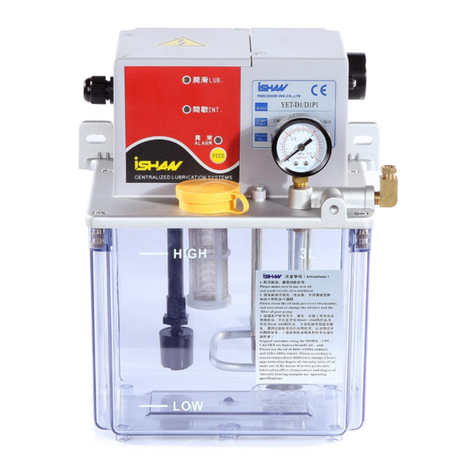
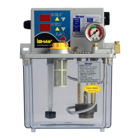
iSHAN YET-A1 User manual

1 - 25
裕祥集中潤滑給油裝置
Centralized Lubrication Systems
(電動注油機)
(Automaticlubricator)
YET-A1 / YET-A1P1
抵抗式電動注油機
Resistance type automatic lubricator
YET-A2/ YET-A2P2
容積式電動注油機
Piston type automatic lubricator
操作手冊
Operation Manual
感謝您購買裕祥集中潤滑給油系統,爲了適當使用而無問題,請詳細閱讀本手冊
並確遵指示。
Welcome on using an iSHAN centralized lubrication systems. Read this owner's
manual before installing, operating or maintaining the product. Failure to follow
theinstructions and safety precautions in this owner’s manual could result in serious injury,
death, or propertydamage. Keep for future reference.

2 - 25
目錄
1.應用範圍 ........................................................................................................................................ 3
2.基礎操作 ........................................................................................................................................ 3
2-1 安全措施 ................................................................................................................................... 3
2-1.1 安裝前 ............................................................................................................................... 3
2-1.2 加油之前 ........................................................................................................................... 3
2-1.3 控制器的安全措施 .......................................................................................................... 3
2-1.4 發生故障時 ....................................................................................................................... 4
2-2 注油機組成元件 ................................................................................................................ 4
2-3 產品標籤 ............................................................................................................................... 5
2-4 安裝 ........................................................................................................................................... 6
2-4.1 安裝注油機 ....................................................................................................................... 6
2-4.2 加入油料 ........................................................................................................................... 6
2-4.3 油管接法 ........................................................................................................................... 6
2-4.4 安裝電源和警報器 .......................................................................................................... 6
3.使用說明 ........................................................................................................................................ 8
3-1 控制台 ....................................................................................................................................... 8
3-2 間歇 / 潤滑時間數值顯示 ..................................................................................................... 8
3-3 設定間歇 / 潤滑時間 ............................................................................................................. 8
3-4 重新啟動 ................................................................................................................................... 8
3-5 操作模式的設定 ...................................................................................................................... 8
3-5.1 動作說明 ........................................................................................................................... 9
3-6 補充油料 ................................................................................................................................... 9
4.保養 ................................................................................................................................................ 9
5.故障排除 ...................................................................................................................................... 10
6.保証 .............................................................................................................................................. 11
7.注意事項 ...................................................................................................................................... 11
8.技術資料 ...................................................................................................................................... 11
8-1 規格 / 介面 ......................................................................................................................... 11
8-2 接線圖 .................................................................................................................................. 12
9 聯繫方式 ...................................................................................................................................... 25
3 - 25
1.應用範圍
裕祥集中潤滑給油裝置可用來潤滑滾珠軸承、滑動軸承、平滑動軌道、圓筒滑動
軌道、線性滑軌、凸輪、齒輪、鏈條…等等。
裕祥集中潤滑給油裝置適用於各式機械的潤滑,例如車床、銑床、沖床、研磨機,
等等。
它可以對不同機器的各個潤滑點同時作潤滑。
YET 機型適用 30 to 250 cSt 的潤滑油;限用新油。
YET-A1 和YET-A2 的設計重點是間歇性潤滑。間歇時間數值可設定 1到
999(單位:秒/分/時)。潤滑時間數值則可設定為 1 到999 (單位:秒/),注油機出廠已
設定為潤滑:秒,間歇:分。YET-A1 和YET-A2 注油機允許用戶做時間性控制。
YET-A1最大出油量為每分鐘 200 ml。
YET-A2最大出油量為每分鐘 150 ml。
YET-A1 的設定壓力為 7 kgf/cm2,YET-A2 的設定壓力為 15 kgf/cm2。為保護週
邊設備,設有釋壓閥來固定潤滑時的壓力。YET-A2 可以使用容積式分配器,配合脫
壓裝置 , 在間歇時間舒解油管內的油壓。
YET 機型會在油量不足時,發送出警報聲響及燈號,並會停止送油的動作。 為
採取更進一步的對應缺油措施,例如讓需要潤滑的機器停止工作,等等,可依用戶的
需求將潤滑機台的異常出力接點連接到機器接點、電腦、或其它儀器設備上。
注意:潤滑與間歇時間設定時,最長潤滑時間≤2min,最短間歇時間≥3min。
2.基礎操作
2-1 安全措施
2-1.1 安裝前
*安裝前先確定電源接線﹑輸入電壓是否正確。
*安裝前確定各零組件電器規格是否正確
*裕祥集中潤滑給油裝置不可使用於以油料潤滑機器以外的其他用途。
2-1.2 加油之前
*潤滑油的黏度應介於 30~250 cSt,注意 ! 若使用油料的黏度高於 250 cSt 注油機可能
會燒毀。若黏度低於 30 cSt 可能會造成壓力或流量不足以及打不出油的情況。
*只可使用新的油料,忌用已使用過的油來作潤滑。
*不可加入化學物質或水。
*清除油箱內的顆粒物塵埃,以確保正常潤滑。
*加油到油箱時應注意勿濺到電子控制器。
2-1.3 控制器的安全措施
*勿使控制器和水或油接觸, 以免造成失序。

4 - 25
2-1.4 發生故障時
*只有裕祥公司的客戶服務人員有權進行維修, 並須使用原廠之備用零件。
2-2 注油機組成元件
(圖一)
1 電子箱頂蓋 8 液位開關
2 電纜固定頭 9 齒泵
3 YET-A控制面版 10 釋壓閥
4 丸蓋 11 脫壓機構(A2專用)
5 上蓋 12 直角接頭
6 加油口濾網 13 壓力錶
7 油箱 14 電子箱外殼

5 - 25
2-3 產品標籤
規格貼紙 小心觸電
電子箱外殼右前方 電子箱外殼上方
配線貼紙 注意事項 操作說明
電子箱外殼
內部
油箱正面右上方 油箱左側

6 - 25
2-4 安裝
2-4.1 安裝注油機
安裝時 (見圖二) 用兩支螺絲(1)將上
蓋(2)的固定孔鎖在機器上的螺孔(3),機器
上兩孔相距(2L 爲172~180mm,3L 爲
190~205 mm,4L 爲230~250 mm)。裝設
高度應高於地面 0.6 ~ 1.7 公尺。
(圖二)
2-4.2 加入油料
取下丸蓋並注入乾淨未使用過
的潤滑油到油箱內 (見圖三),直 到
八分滿的高度,然後蓋上丸蓋,只能
使用黏度介於 30 ~ 250cSt 的潤滑
油。
注意 ! 若使用油料的黏度高於
250cSt 注油機可能會燒毀。
(圖三)
2-4.3 油管接法
現在開始接油管 (見圖四),接頭位於
注油機右側。將接頭 (1)上的套管帽
(1) 、套管 (2) 取出,並將其套在油管
(4) 上,然後將油管插入接頭 (3) 內,
並使油管 (4) 伸出套管 (2) 至少 1 mm
以上,將油管 (4) 扶正以套管帽 (1)
鎖緊以免漏油。
(圖四)
2-4.4 安裝電源和警報器
欲連接電源及警報的電纜時,先確定該電纜沒有通電。接著請鬆開電源和警報接

7 - 25
點所在的電子箱之螺絲 (圖五)。電子箱左方有一電纜固定頭。 請旋開此
電纜固定頭(圖六),並將此電纜固定頭穿套過電纜, 再把電纜從開口推穿進電子箱,
把電纜接到電源及警報的接點 (圖七)。要連接時,先鬆開地線接點的螺絲,再把地線
接上去,並拴緊螺絲以固定之①。接著依正負方向把電纜接到 電源 "POWER" 接點②
上。
完成後將配線盒蓋上,並將電纜固定頭旋緊以免電線被拉出配線盒造成斷路 (參考
圖九)。將電源接上,若接線正確,在控制台上的潤滑指示燈 (橙燈) 會亮起 (圖十)。
同時注油機以開機即潤滑開始運轉。
(圖五) (圖六) (圖七)
通電時
Connection NC - COM (常閉) COM - NO (常開)
不缺油時 電路導通 電路不導通
缺油時 電路不導通 電路導通
(圖八) (圖九)

8 - 25
3.使用說明
3-1 控制台
(圖十)
3-2 間歇 / 潤滑時間數值顯示
間歇/潤滑時間的設定值可以壓住控制台上的任一鍵 ”▲”或”▼”1
至2秒而由顯示螢幕讀取。如果未按任何鍵,注油機 5秒鐘後會自動重新啟動。
在間歇期間,間歇時間顯示螢幕會顯示剩餘的間歇時間,潤滑時間顯示螢幕會顯
示設定值。同理,在潤滑期間,潤滑時間顯示螢幕會顯示剩餘的潤滑時間,間歇時間
顯示螢幕會顯示設定值。在任何時間按 ”▲”或”▼”鍵約 2秒可讀取潤滑
/間歇時間的設定值。如果未再按任何鍵,注油機 2秒鐘後會自動重新啟動。
3-3 設定間歇 / 潤滑時間
先按住間歇 / 潤滑時間設定鍵(加鍵或減鍵)的任一個 1至2秒。時間顯示螢幕會
顯示之前間歇 / 潤滑時間的設定值。壓一下 ”▲” 間歇 / 潤滑時間會增加 ; 持續
壓住則會快速增加。壓一下 ”▼”間歇 / 潤滑時間會減少﹔持續壓住則會快速減
少。間歇時間的單位可設定為秒、分、時,潤滑時間的單位設定為秒,數值由 1到999
可調整(注油機出廠已設定為潤滑:秒,間歇:分)。若注油機在設定模式,注意間歇 /
潤滑兩指示燈都會閃爍。 設定好間歇 / 潤滑時間後勿再按任何鍵,注油機 5秒鐘後
會將新的設定儲存並自動重新啟動。此時指示燈不再閃爍而是潤滑時潤滑指示燈亮﹔
間歇時間歇指示燈亮,另一指示燈不亮。
3-4 重新啟動
任何時候按強制潤滑鍵 (圖十) 1 至2秒,注油機會依目前間歇 / 潤滑時間的設
定自動重新啟動,可以有強制潤滑的效果。
3-5 操作模式的設定
注意!只有裕祥公司客戶服務部工作人員被授權更改注油機的初始設定,使用者只可
以進行基本功能的設定。
潤滑時間顯示
間歇時間顯示
潤滑指示燈(黃燈)
潤滑時間增加鍵
潤滑時間減縮鍵
間歇時間減縮鍵
異常指示燈(紅燈)
RES 強制潤滑
間歇指示燈(綠色)
間歇時間增加鍵

9 - 25
3-5.1 動作說明
潤滑指示燈
間歇指示燈 異常指示燈
蜂鳴器 注油馬達 異常接點
計次 一直亮著 OFF OFF
潤滑時
ON
OFF
計時
0.1
秒
0.5
秒閃爍
0.5
秒閃爍
OFF OFF
潤滑時
ON
OFF
計時 1秒
1
秒閃爍
1
秒閃爍
OFF OFF
潤滑時
ON
OFF
計時 1分
2
秒閃爍
2
秒閃爍
OFF OFF
潤滑時
ON
OFF
計時
1
小時
5
秒閃爍
5
秒閃爍
OFF OFF
潤滑時
ON
OFF
設定單位
同時閃爍
同時閃爍
OFF
按鍵時叫
0.2S
OFF OFF
設定時間
同時閃爍
同時閃爍
OFF
按鍵時叫
0.2S
OFF OFF
壓力異常
0.5
秒閃爍
OFF
0.5
秒閃爍
ON OFF ON
油位不足 OFF
0.5
秒閃爍
0.5
秒閃爍
ON OFF ON
按立即潤滑
2
秒後
ON
OFF OFF OFF
2
秒後
ON
OFF
3-6 補充油料
油的高度必須大約介於油箱三分到八分滿之間。如果油的高度比浮動開關位
置還低,潤滑機會停止動作並送出一個警報信號。此時請加入新油 (見圖三)﹐將
油箱蓋打開並倒入新油。
注意! 切勿使用已用過的潤滑油。
4.保養
裕祥集中潤滑給油裝置的保養十分容易,為維護裝置請定期清理油箱。若油
箱底部或濾油網發現雜質,請將注油機停止並將油箱四個角落的螺絲拆下,使油
箱與注油機其他部份分離,油箱清洗後請將螺絲裝迴旋緊。
為了避免人為操作不當造成故障,下列事項請確實遵守:
à關機後須等待二十秒才能再開機以維護電子控制系統穩定。
à不可私自變更本公司機台的出廠設定,以免造成故障。
àYET-A1 之出油接頭為特殊止逆裝置,不得私自更換。
àYET-A2 之出油口不可裝止逆接頭以免無法正常供油。

10 - 25
5.故障排除
! 作任何檢查前應先關閉電源。
! 對於未列於以下表格內的異常狀況,請勿自行修理及拆解 (請向本公司或經銷商
諮詢)。
異常狀況 異常原因 故障排除
指示燈不亮
電源切斷 檢查電源線
指示燈失效 更換指示燈
電源接錯,造成內部線路燒毀
檢查電源線是否接錯位置或接
錯電壓,標示原因並將機台寄回經
銷商或本公司維修。
指示燈亮但無油
流出
缺油(油量不足) 請補充油料。
液位開關異常 更換液位開關。
幫浦或馬達故障 更換幫浦馬達
油流出量不足 濾油網阻塞 清理吸油組之濾網
油黏度太高或太低 使用適當黏度的油品
油管與注油機接
頭處漏油 安裝錯誤 套管必須完全套入管子並使油
管放進接頭後伸出套管至少 1 mm
以上的長度。
注油機運轉,但
油未流出
管路中有空氣 等待約一分鐘若無油流出,將
直角接頭和套管帽放鬆待油流出後
再瑣緊。
拆解注油機出口的油
管,檢視打油時是否有油流
出,若有表示注油機正常,可
能是機械的配管阻塞或破裂。
查出那段管路異常並加以處
理。
拆解注油機出口的油
管,檢視打油時是否有油流
出,若無,可能是齒泵卡死或
馬達異常。
齒泵卡死 : 油太髒,清理油箱雜質
並將機台寄回經銷商或本公司維
修。
馬達異常 : 將機台寄回經銷商或本
公司維修。
若有安裝壓力開關,檢查
壓力開關是否正常。若正常表
示管中壓力無法建立,可能是
管路破裂或馬達故障。
若壓力開關或微動開關故障需
更新。若管內壓力無法建立,參考
本表並排除故障。

11 - 25
漏電 關閉電源並檢查接地線
是否連接正確、配線盤是否受
潮。
標示漏電情況並將機台寄回本
公司檢修。
6.保証
此裝置保證期間爲 12 個月,在保證期間免費維修只有在裝置未被擅改並且完整,
未拆封的狀態寄回給裕祥服務人員始予接受。請勿在未商議的情況下寄回剩餘零件,
收件人負擔運費的方式需經本公司服務人員同意。此保證包含原廠材料和製造瑕疵,
若因爲天災或未遵照本操作手冊而至損壞則不在保證之內。
7.注意事項
注意 : 本公司得不經通知顧客自行從事產品技術及外觀上的改進。本手冊之說明及資
訊亦不再保證之內。因此,不得以此進行法律訴訟。
8.技術資料
8-1 規格 / 介面
YET-A1 YET-A2
電源供應 AC 110 V or AC 220 V AC 110 V or AC 220 V
消耗功率 (max.) 100W 100W
容許粘度範圍 30 ~ 250 cSt 30 ~ 250 cSt
吐出量 200 cc/min 150 cc/min
最大吐出壓力 kgf/cm27±1 (kgf/cm2) 15±1 (kgf/cm2)
管路接頭直徑 ∮4 或∮6 mm ∮4 或∮6 mm
尺寸 (高×寬×長)2L: 255×150×205
3L: 275×175×227
4L: 273×180×275
2L: 255×150×205
3L: 275×175×227
4L: 273×180×275
油箱容積 2L/3L/4L 2L/3L/4L
操作溫度 0 ~ 50 ℃0 ~ 50 ℃
壓力錶最大規格 15 (kgf/cm2) 35 (kgf/cm2)
壓力開關作用壓力 (選配件) 2.1 (kgf/cm2) 11.5 (kgf/cm2)
異常輸出接點容量 3A 3A

12 - 25
8-2 接線圖

13 - 25
Index
1 SCOPE OF APPLICATION ......................................................................................................... 14
2 BASIC OPERATION ................................................................................................................... 14
2-1 SAFETY INFORMATION ........................................................................................................... 14
2-1.1 Before installing ................................................................................................................ 15
2-1.2 Before lubricant filling ...................................................................................................... 15
2-1.3 Control panel safety information ...................................................................................... 15
2-1.4 Faults ................................................................................................................................. 15
2-2 PARTS OF LUBRICATION UNIT .................................................................................................... 16
2-3 LABEL INSTRUCTION .................................................................................................................. 17
2-4 INSTALLATION ......................................................................................................................... 18
2-4.1 Positioning and mounting ................................................................................................. 18
2-4.2 Filling Oil .......................................................................................................................... 18
2-4.3 Lubrication line connection ............................................................................................... 18
2-4.4 Wiring and alarm .............................................................................................................. 19
3. GENERAL INFORMATION ...................................................................................................... 20
3-1CONTROL PANEL ......................................................................................................................... 20
3.2 INTERMITTENCE TIME/ LUBRICATION TIME DISPLAY ................................................................ 20
3.3 INTERMITTENCE TIME/ LUBRICATION TIME SET UP .................................................................... 20
3-4 RES BUTTON ............................................................................................................................. 21
3-5 OPERATING MODE SETTING ........................................................................................................ 21
3-5.1 DISPLAY & ACTION INSTRUCTION .......................................................................................... 21
3-6 REFILLING LUBRICANT ............................................................................................................... 21
4 MAINTENANCE ......................................................................................................................... 22
5 FAULTS / TROUBLESHOOTING .............................................................................................. 22
6 WARRANTY ................................................................................................................................ 23
7ANNOUNCEMENT ...................................................................................................................... 23
8.TECHNICAL DATA .................................................................................................................... 24
8-1 SPECIFICATION ....................................................................................................................... 24
8-2 WIRE DIAGRAMED ..................................................................................................................... 24
9 CONTACT US .............................................................................................................................. 25
14 - 25
1 Scope of application
iSHAN centralized lubrication systems are designed to lubricate ball bearings, flat
bearings, flat slideways, circular slideways, linear guides, cams, gears, chains, etc..
iSHAN centralized lubrication systems are suitable for the lubrication of various machines,
such as lathes, mills, presses, planner, grinder, etc. It is fit to control different lubricating
points at the same time against different machines.
The YET lubrication units are suitable for using lubricant with a viscosity range at 30 to 250
cSt during it is running. Only new lubricant shall be used.
The design of YET series is to operate intermittently with an interval-controlled supply of
lubricant to the lubrication point. The interval time can be set from 1 to 999 per
second/minute/hour. The lubrication time can be set from 1 to 999 per second. The default
time unit of lubrication unit is second for lubrication and minute for intermittence. The user
can adjust time for lubrication quantity.
The maximum discharge rate of YET-A1 pump is 200 ml/min.
The maximum discharge rate of YET-A2 pump is 150 ml/min.
The max. discharge pressure for YET-A1 series is 7kgf/cm2, and YET-A2 series is
15kgf/cm2. The lubrication unit contains a pressure relief valve in order to prevent injury,
death, or property damage. YET-A2 model operates with piston type distributors and
through dump valve release pressure from the main line at the interval time.
For safety, a pressure switch should be mounted to monitor the system. The pressure
switch monitors whether the required pressure build-up occurs in the centralized lubrication
system during the pump cycle time and detects any leaking or lubrication connection
damage. The level switch is design to monitor the filling level and shut down the lubrication
unit when the lubricant is insufficient. To get further safety, the lubrication unit can connect
to other monitored device properly to enhance the alarm system.
Warning ! The maximum lubrication time is less than 2 minutes and the
minimum intermittent time is more than 3 minutes.
2 Basic operation
2-1 Safety information

15 - 25
2-1.1 Before installing
!Before installing, read the manual for the correct connection of the power. To prevent
chance of serious injury, death or property damage, disconnect the product from main
power supply before working on it.
!Comply with the specifications on the rating plate of the motor or the electrical
components..
!iSHAN centralized lubrication systems must not be used in other purposes other than
lubricating machines.
2-1.2 Before lubricant filling
You must observe the machinery manufacturer's information on the lubricants
to be used in the machinery.
!Use only new oil with a permitted range of oil viscosity from 30 to 250cSt. Warning !
Motor jammed or burned due to high resistance which caused by delivering higher than an
oil viscosity of 250cSt, no pressure build-up in centralized lubrication system or insufficient
oil delivery caused by pumping lower than an oil viscosity of 30cSt result in centralized
lubrication system failure.
! Only clean lubricant may be added. Please never fill with used oil.
!Never fill with chemical substances, water or hazardous fluids.
! All components of the lubrication line system - including reservoir, pipes, hoses, cut-off
valves, control valves, fittings, and so on - must be carefully cleaned before installation.
2-1.3 Control panel safety information
!In order to avoid disorders of the control panel, never let it have contact with water or oil.
2-1.4 Faults
! Only qualified, instructed specialists who are authorized by iSHAN may repair lubricators
and must use the original spare parts.

16 - 25
2-2 Parts of lubrication unit
1 Cover 8 Level switch
2 Cable gland 9 Gear pump
3 Control panel 10 Relief valve
4 Oil tank cap 11 Dump valve(for A2)
5 Mounting board 12 Elbow adapter
6 Oil inlet filter 13 Pressure gauge
7 Reservoir 14 Housing
Fig.1

17 - 25
2-3 Label instruction
Model label Electric Shock
Positioned on the front upper right side of housing Positioned on the cover o
f
housing
Wiring
instruction
Warning Operation instruction
Positioned
inside housing Positioned on the front upper right side of
the reservoir Positioned on the left side of the
reservoir

18 - 25
2-4 Installation
2-4.1 Positioning and mounting
(Fig.2)The lubrication unit is attached to the
intended mounting location (3) using appropriate
fastening materials (1).The mounting dimensions of
fixing holes for 2L are measured between 172 to
180mm ; 3L between 190 to 205mm ; 4L between
230 to 250mm. The installation location should be
spaced between 0.6m to 1.7m above the ground.
Fig.2
2-4.2 Filling Oil
Remove the oil tank cap and fill clean and
non-used oil into the tank and add up to the MAX
mark (Fig. 3). Please note that only use permitted
range of oil viscosity between 30cSt to 250cSt.
Warning! Motor jammed or burned due to high
resistance which caused by delivering higher than an
oil viscosity of 250cSt.
Fig.3
2-4.3 Lubrication line connection
(See Fig. 4) Solderless tube connection (double
tapered sleeves) can be used. The tube (4) must go
through compressed bushing (1) and double tapered
sleeve (2). To avoid any leaking during running
service time, it should be observed up to
1mmdistance between the tube end to the double
sleeve. Insert tube end into counterbored port (3) up
to the stop. First tighten compressed bushing
finger-tight by hand. Then turn another 11/2 turns.
Fig.4

19 - 25
Fig.5 Fig.6 Fig.7
Power switched on
Connection NC - COM COM - NO
Sufficient, lubricant The contact closed The contact open
Insufficient, lubricant The contact open The contact closed
Fig.8 Fig.9
2-4.4 Wiring and alarm
Warning !! To prevent chance of serious injury, death or property damage,
disconnect the product from main power supply before working on it.
Install a fuse between the power supply and the product is strongly recommended!
The electrical circuit diagram of the lubrication unit is affixed inside the unit and can
be accessed by removing the cap.
Remove the cap (Fig.5) and inside you can see terminal plate and cable gland nut.
Loosen cable gland (Fig.6) and then insert cable through the cable gland hole (Fig.7) to
wire up. Fix the cable gland to the housing.
After electric connection is completed and then the power switched on, the level switch
would send a signal to the lubrication unit with alarm and alarm indicator light and the
motor stops at the same time when lubricant is insufficient. The user can connect terminal

20 - 25
point (remark NC/COM/NO) to other detectors or monitors for the application to stop
machine when the lubricant is insufficient.
After the electrical connection is finished, tighten the cable gland (Fig.9) and fix the
cover. Then turn on the power and the lubrication indicator light on the panel will lamp and
the motor feeds oil if the electrical connection is correct.
3. General information
3-1Control panel
Fig.10
3.2 Intermittence Time/ Lubrication Time Display
The setting of intermittent time and lubrication time can be adjusted by pressing any
of ”▲”or ”▼”for two seconds and read from value from the display. If no
further action, the timer will restart after 5 seconds.
Intermittence time display indicates the set value and the remaining of intermittent time
during the lubrication unit working. Lubrication time display indicates the set value and the
remaining of intermittent time during the lubrication unit working. When pressing any of
the ”▲”and ”▼”of Lubrication Time/ Intermittence Time for two seconds,
the set-up value will be shown. If no further action, the timer will restart after 2 seconds.
3.3 Intermittence Time/ Lubrication Time set up
Press any of ”▲”or ”▼”for two seconds and then enter time setting
mode by pressing ”▲”or ”▼”to adjust time from 1 to 999 for interval and
lubricating. Continuously press ”▲”or ”▼”to fast increase or decrease value.
During time setting mode, two indicators will spark in the same time.
Time unit for intermittence is minute ; Time unit for lubrication is second
Indicator light of LUB.(Yellow)
Display of INT. Time
Display of LUB. Time
Indicator light of INT. (Green)
Indicator light of alarm (Red)
Increase of LUB. time
Decrease of INT. time
Increase of INT. time
Decrease of LUB. time
RES (Feed pushbutton)
Other manuals for YET-A1
1
This manual suits for next models
3
Table of contents
Other iSHAN Lubrication System manuals
Popular Lubrication System manuals by other brands

Graco
Graco FIRE–BALL 300 Air Motor Muffler Kit Instructions-parts list

SKF
SKF HTL201 EEX operating instructions

Perma
Perma FUTURA PLUS operating instructions

MEMOLUB
MEMOLUB HPS user guide

Groeneveld
Groeneveld Multiline AC Series installation manual

IMI
IMI norgren Micro-Fog L68C Installation & maintenance instructions

Gruetzner
Gruetzner Lubricus LUB-V1 operating instructions

Flowserve
Flowserve SLD installation instructions

Lincoln
Lincoln SKF TLMR 101 Original operating instructions

SKF
SKF LUBRILEAN Vario operating instructions

Groeneveld
Groeneveld EcoPlus User instruction

SKF
SKF GVP-S-034-3D+924 Installation and operation manual