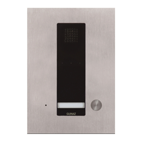
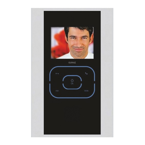
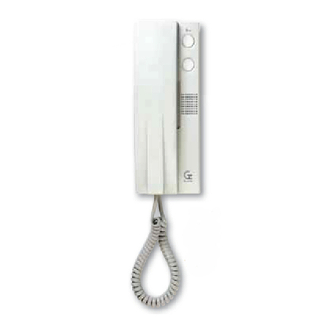
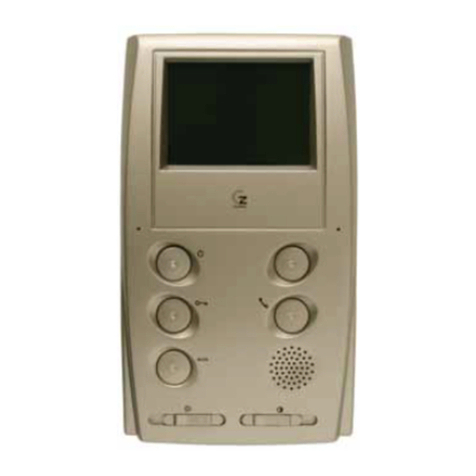
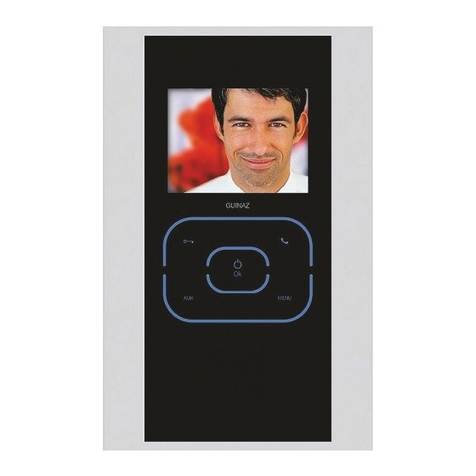
Guinaz A2410 User manual

GUÍA DE INSTALACIÓN INSTALLATION GUIDE
GRUPOS CONTROL AUDIO
CON SELECTOR DE
ACCESOS PARA SISTEMAS
AUDIO Y VíDEO CON
TELEFONO
REF. A2410
AUDIO CONTROL GROUP
WITH ACCESS SELECTOR
FOR AUDIO AND VIDEO
WITH TELEPHONE SYSTEMS
REF. A2410

CARACTERÍSTICAS GENERALES. GENERAL CHARACTERISTICS.
G503144 - R00
2
Audio telephones) or colour video monitors with
telephone) installation for dwellings with more than
one access. Any dwelling that is part of the installation
can be called from each access, with call
confirmation in the street panel and automatic start-
up of the monitor.
Group A2410 includes access control, apart from
basic audio and video communication between the
street panel and the dwellings. It has four micro-
switches, whose functions will be explained further
on, to configure each street panel.
The panel emits an acoustic warning when a call is
made and the line is busy with another street panel,
or when another street panel with higher priority
cancels the call in progress. Optionally, viewer P2600
can be installed. A card with personal information
can be fitted in the upper part and the lower part
lights up with the BUSY message while the busy line
acoustic warning is given by group A2410. Viewer
P2600 is connected to group A2410 by means of
two connectors supplied with the viewer itself.
The steps for installation are shown in the different
sections, with the street panel offering several
adjustments for each type of installation, such as
the position of the telecamera, sound volume, etc.
The type of installation is that known as 4 + n for
the entryphone, and 5 + n + coaxial or twisted pair
cable for the video entryphone, where n is the
number of calls.
This device is for exclusive use in GUINAZ entryphone
and video entryphone installations. Its installation
will be carried out as specified in this guide while
applying the regulations in force.
Internal handling will only be performed by specialised
personnel and always with the equipment
disconnected from the mains.
Always keep the ventilation slits of this device clear;
under no circumstance will they be obstructed or
covered.
Ins alación audio ( eléfonos) o vídeo color (moni ores
con auricular) para viviendas con más de un acceso.
Desde cada acceso se puede llamar a cualquier
vivienda de la ins alación, con confirmación de
llamada en placa calle y au oencendido del moni or.
El grupo A2410, además de la función básica de
comunicación audio y vídeo en re la placa calle y las
viviendas, incorpora el con rol de accesos. Para
configurar cada placa calle, posee cua ro micro-
in errup ores cuya funcionalidad se explica más
adelan e.
La placa calle emi e un aviso acús ico cuando se
in en a realizar una llamada y la línea es á ocupada
por o ra placa calle, o cuando o ra placa calle con
prioridad superior cor a la llamada en curso.
Opcionalmen e puede ins alarse el visor P2600. En
la par e superior se puede colocar una arje a con
información personalizada y en la par e inferior se
ilumina el mensaje OCUPADO a la vez que se emi e
el aviso acús ico de línea ocupada desde el grupo
A2410. El visor P2600 se conec a al grupo A2410
median e dos la iguillos suminis rados en el propio
visor.
Los pasos de la ins alación vienen reflejados en los
diferen es apar ados, disponiendo en placa de calle
de varios ajus es para cada ipo de ins alación, ales
como la posición de la elecámara, el volumen del
sonido, e c.
Los ipos de cableado son los ya conocidos de 4+n
para por ero, y 5+n+cable coaxial o par renzado
para videopor ero, donde "n" es el número de
llamadas.
Es e disposi ivo es para uso exclusivo en ins alaciones
de por eros y videopor eros GUINAZ. Su ins alación
debe realizarse al y como se especifica en es a guía
y aplicando la reglamen ación vigen e.
La manipulación in erna de es e produc o sólo puede
realizarse por personal especializado, y siempre con
el equipo desconec ado de la alimen ación.
Man enga siempre despejadas las ranuras de
ven ilación del disposi ivo; en ningún caso pueden
quedar obs ruidas o apadas.
In this pamphlet, you will be informed on how to
perform alterations, such as adding other
supplementary telephones and monitors or even the
easiest way of distributing the video signal.
A lo largo de es e folle o, se le informará sobre cómo
realizar modificaciones, ales como añadir o ros
eléfonos y moni ores suple orios, o incluso la manera
más fácil de dis ribuir la señal de vídeo.

G503144 - R00 3
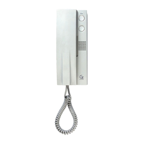
TELÉFONO ALFA T1150. ALFA TELEPHONE T1150.
Pulsador abrepuer as.
Door opener pushbutton.
Pulsador auxiliar, libre de po encial.
Supplementary pushbutton, potential-free contact.
1. Pulsador de encendido/apagado. U ilizado para conec ar
y desconec ar el moni or.
On/off push-button. Used to connect and disconnect the
monitor.
2. Pulsador abrepuertas. Sirve para abrir la puer a.
Door opener push-button. This is pressed to open the
door.
3. Pulsador auxiliar. U ilizado para funciones ajenas a la
ins alación del videopor ero (iluminación escalera, aper ura
segunda puer a....). Con ac o libre de po encial.
Supplementary push-button. Used for functions other
than those of the video entryphone installation lighting of stairs,
opening a second door...). Potential-free contact.
4. Ajuste de brillo. Regulación del brillo de la imagen que
aparece en pan alla.
Brightness adjustment. To adjust the brightness of the
image appearing on the screen.
5. Ajuste de color. Regulación de color de la imagen que
aparece en pan alla.
Colour adjustment. To adjust the colour of the image appearing
on the screen.
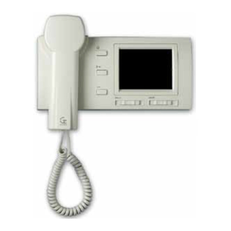
MONITOR M1720D. MONITOR M1720D.
En el caso de portero, su funcionamiento es el
siguiente:
1. Al recibir una llamada, el eléfono emi e el ono de
llamada y se escucha la confirmación de llamada
en la placa calle.
2. Para es ablecer comunicación en re el eléfono y la
placa calle, descuelgue el auricular.
3. Si se quiere abrir la puer a, accionar el pulsador
abrepuer as del eléfono.
4. Si desea erminar la comunicación sin abrir la puer a,
vuelva a colgar el auricular en la base del eléfono.
5. El eléfono T1150 dispone de un pulsador auxiliar
libre de po encial, que puede usarse para o ras
aplicaciones ajenas a la ins alación.
It wor s in the following way in the case of an
entryphone:
1. When receiving a call, the telephone emits the call
tone and call confirmation can be heard from the
street panel.
2. Unhook the telephone to establish audio contact
between the telephone and the street panel.
3. Press the door opener pushbutton on the telephone
to open the door.
4. Hang up the telephone to end the communication
without opening the door.
5. Telephone T1150 has a potential-free pushbutton
that can be used for other applications not
belonging to the installation.

In the case of the video entryphone, it wor s in
the following way:
1. When receiving a call, the image appears instantly
on your monitor.
2. While you see the visitors, these are not warned
about your presence in the dwelling until audio
contact is established.
3. To establish audio contact unhook the telephone.
The image timer will restart when the telephone is
unhooked.
4. The image will be disconnected 40 seconds after
starting. The image is also turned off by hanging up
the telephone or by pressing the on/off button .
5. The door is opened by pressing the door opener
pushbutton .
6. To perform video surveillance, press the on/off
button . Video surveillance will automatically end
40 seconds after it is initiated, or by once again
pressing the on/off button .
7. For other applications it has a supplementary
potential-free pushbutton .
8. It has brightness and colour adjustments to achieve
an appropriate image quality.
G503144 - R00
4
En el caso de videoportero, su funcionamiento
es el siguiente:
1. Al recibir una llamada, la imagen aparece
ins an áneamen e en su moni or.
2. Mien ras us ed visualiza la visi a, és a no advier e
su presencia en la vivienda has a que no se
es ablece con ac o audi ivo .
3. Para es ablecer con ac o audi ivo descolgar el
auricular. La emporización de la imagen se reinicia
al descolgar el auricular.
4. La imagen se desconec ará una vez ranscurridos
40 seg. desde que se inició. La imagen ambién se
apaga al colgar el auricular o pulsando el bo ón de
encendido/apagado .
5. La aper ura de la puer a se realiza median e el
pulsador de abrepuer as .
6. Para realizar videovigilancia, pulsar el bo ón de
encendido/apagado . La videovigilancia finalizará
au omá icamen e a los 40 seg. de iniciada, o
pulsando de nuevo el bo ón de encendido/apagado
.
7. Para o ras aplicaciones, cuen a con un pulsador
auxiliar libre de po encial.
8. Para conseguir una adecuada calidad de imagen
dispone de ajus e de brillo y color.
Las opciones de configuración median e los microin errup ores son:
The configuration options by means of micro-switches are the following:
Microinterruptor 1 MAIN / SEC): Configura la placa calle como Principal (MAIN)
o Secundaria (SEC). En oda ins alación debe configurarse una placa calle como
principal y el res o como secundarias. La placa calle principal es el acceso seleccionado
por defec o al descolgar el auricular o al realizar videovigilancia desde una vivienda.
Las placas calle secundarias ienen un ono de llamada dis in o de la placa calle
principal.
Micro-switch 1 (MAIN / SEC): This configures the street panel as Main MAIN) or
Secondary SEC). In any installation, one street panel will be configured as being
the main one and the rest as secondary ones. The main street panel will be the
access selected by default when unhooking the telephone or when performing video
surveillance from a dwelling. Secondary street panels have a different call tone from
that of the main street panel.
GRUPO CONTROL AUDIO A2410. AUDIO CONTROL GROUP A2410.

G503144 - R00 5
Microinterruptor 2 P. Hi / P. Lo): Define la prioridad de la placa calle respec o del
res o. Cuando se es ablece comunicación desde una placa calle con prioridad al a
(P. Hi), el res o de placas calle quedan en es ado ocupado. Las placas calle configuradas
con prioridad baja (P. Lo) pierden la comunicación cuando se llama desde o ra placa
calle. En una misma ins alación pueden coexis ir placas calle con prioridad al a y
placas calle con prioridad baja.
Micro-switch 2 (P. Hi / P. Lo): This defines the priority of the street panel with regard
to the rest. When communication is established from a street panel with high priority
P. Hi), the rest of the street panels go into busy status. The street panels configured
with low priority P. Lo) lose their communication when a call is made from another
street panel. Street panels with high priority and those with low priority may coexist
in the same installation
Microinterruptor 3 T.MAX / T.MIN): Es e microin errup or es ac ivo cuando la placa
calle es á configurada en prioridad al a (microin errup or 2 en posición P. Hi). Define
el iempo que la placa calle funciona en prioridad al a; pasado es e iempo, la placa
calle funciona como prioridad baja. En la posición T.MAX la placa calle funciona en
prioridad al a 90 segundos desde que se produce la llamada. En la posición T.MIN,
el iempo es de 30 segundos.
Micro-switch 3 (T.MAX / T.MIN): This micro-switch is active when the street panel
is configured with high priority micro-switch 2 in position P. Hi). This defines the time
the street panel works with high priority; after this time, the street panel works with
low priority. In the T.MAX position, the street panel works with high priority for 90
seconds from the moment the call is made. The time period is of 30 seconds In the
T.MIN position.
El cable 14 de la fuen e de alimen ación F1320 debe
conec arse a la borna 14F del grupo A2410. La
alimen ación de la elecámara se realizará conec ando
la borna 14T del grupo A2410 con la borna 14 de la
elecámara.
Todos los grupos A2410 de una ins alación deben
es ar conec ados en re si median e la borna 9.
En rada cable
de vídeo desde
la elecámara.
Video cable
input from
camera.
Salida cable de vídeo
hacia las viviendas o
hacia o ra placa de
calle.
Video cable output
towards dwellings or
another street panel.
En rada cable de
vídeo desde o ra
placa de calle.
Video cable input
from another
street panel.
Cable 14 of power supply F1320 will be connected
to terminal block 14F of group A2410. The camera
will receive power supply by connecting terminal block
14T of group A2410 to terminal block 14 of the camera.
All A2410 groups in an installation will be connected
to each other by means of terminal block 9.
Micro-switch 4 is not used.
After hanging up the telephone, 10 seconds will be
available to re-establish communication with the street
panel from which the dwelling was called. Simply
unhook the telephone once again.
14 is the maximum number of accesses that can be
managed with A2410 audio control groups in the
same installation. The common audio and power
supply wires can start from any street panel of the
installation. However, rise video signal connection
must be used in street panels, going up to the
dwellings from the last connected panel. For this,
group A2410 has several connections for the video
cable:
El microin errup or 4 no se usa.
Después de colgar el auricular, se dispone de 10
segundos para volver a re omar la comunicación
con la placa calle desde la que se había llamado a
la vivienda. Bas a con volver a descolgar el auricular.
El número máximo de accesos en una misma
ins alación que se pueden ges ionar con grupos
con rol audio A2410 es de 14. Los hilos comunes
de audio y alimen ación pueden par ir hacia las
viviendas desde cualquier placa de calle de la
ins alación. Sin embargo, la señal de vídeo debe
conec arse en cascada en las placas de calle y
desde la úl ima placa conec ada subir hacia las
viviendas. Para ello el grupo A2410 dispone de varias
conexiones para el cable de vídeo:

G503144 - R00
6
INSTALACIÓN PLACA DE CALLE. STREET PANEL INSTALLATION.
Suje ar la placa calle
median e dos ornillos.
Attach the street panel with
two screws.
Coloque la caja empo rable.
Place the flush-mounted box.
1
6
2Separar apas, desa ornillar ambos ornillos y ex raer
jun as de módulos.
Separate the covers, unscrew both screws and extract
module joints.
3In roducir módulos y jun as en
el mismo orden que aparece
en la figura.
Insert modules and joints in the
same order as in the figure.
4Colocar marco
superior y apre ar
los ornillos.
Assemble upper
frame and tighten
the screws.
5
Para apertura a la derecha. To open towards the right.
A. Suel e el ornillo izquierdo y afloje el derecho. Unscrew left screw and loosen the right one.
B. Desplace la placa calle hacia la izquierda y fron almen e 1,5 mm. Move the street panel 1.5 mm to
the left and the front.
C. Gire la placa calle. Open the street panel.

G503144 - R00 7
Conec e el grupo con rol audio, grupos
arje eros pulsadores y grupo elecámara según
esquema unifilar.
Connection of the audio control group, the
name tag pushbutton groups and the camera
group according to the single wire diagram.
7
IMPORTANTE: COLOCAR LAS TAPAS
SUPERIOR E INFERIOR ANTES DE CERRAR
LA PLACA CALLE.
IMPORTANT: CLIP ON THE LOWER AND
UPPER COVERS BEFORE CLOSING THE
STREET PANEL.
Cierre la placa de calle apre ando ambos
ornillos.
Close the street panel by tightening both
screws.
910
Ajuste del volumen de placa calle y de monitor
1). Ajuste de posición de la telecámara
2).Configuración de puentes telecámara
consultar página 16).
Adjustment of the street panel and monitor
audio volume 1). Adjustment of the camera
position 2). Configure camera bridges see
page 16).
6bis Para apertura a la izquierda. To open towards the left.
A. Suel e el ornillo derecho y afloje el izquierdo. Unscrew right screw and loosen the left
one.
B. Desplace la placa calle hacia la derecha y fron almen e 1,5 mm. Move the street panel
1.5 mm to the right and the front.
C. Gire la placa calle. Open the street panel.

G503144 - R00
8
COLOCACIÓN DE LOS TARJETEROS. PLACEMENT OF NAME TAGS.
Ex racción del arje ero
del módulo de
pulsadores colocado en
placa calle.
Extract the name card unit
from the push-button
module of the street
panel.
Separar
ranslúcido
de cris al.
Separate
translucent
glass part.
In roducción del
arje ero.
Insert the card.
Inser ar en módulo
de pulsadores has a
clipar. Insert in the
push-button module
until it clips in.
1234
La placa de calle es á suficien emen e
pro egida de las condiciones a mosféricas.
Sin embargo, es convenien e ins alarla en
un lugar en que no afec en direc amen e
agen es como la lluvia, humedad, e c.
Cuando la placa calle es é expues a a la
in emperie se recomienda ins alarla sobre
un marco visera. En el caso de superficies
no lisas, donde la placa calle o el marco
visera no queden perfec amen e sellados
median e las jun as que incorporan, se
recomienda aplicar algún sellan e en oda
la par e superior de la placa calle o marco
visera para evi ar en radas de agua que
puedan dañar el equipo.
The street panel is sufficiently protected
against atmospheric conditions. However, it
is recommendable to install it in a place where
agents such as rain, humidity, etc. cannot
affect it.
When the panel is exposed to the elements
it is recommendable to install it with a visor
frame. In the case of surfaces that are not
smooth, where the street panel or visor frame
are not perfectly sealed with the joints that
are incorporated, then some sort of sealer
should be applied throughout the entire upper
part of the street panel or visor frame to thus
avoid water from penetrating and damaging
the equipment.
En la ins alación de videopor ero, se ha
de escoger un lugar donde no incida
direc amen e una fuen e de luz (sol,
farolas, e c.) sobre la elecámara, para
evi ar el efec o de con raluz en la imagen.
En el caso de que la imagen no sea
ní ida debido a luz insuficien e para la
elecámara, se ha de colocar una
iluminación auxiliar como se indica en
la figura. Es a iluminación auxiliar puede
ins alarse de al forma que sólo se
ilumine la escena cuando haya un
moni or funcionando.
When choosing the location to install a
video door entry system it is important
to find a location where the source of
light sun, street lamps, etc.) does not
directly affect the camera, to thus avoid
the effect of the back light on the image.
If the image is not clear and sharp due
to a lack of light for the camera, then
auxiliary lighting should be placed as is
duly indicated in the figure. This auxiliary
lighting can be installed in such a way
that it only lights up the scene when a
monitor is working.
INSTALACIÓN DE FUENTE DE ALIMENTACIÓN.
INSTALLATION OF POWER SUPPLY.
La fuen e de alimen ación puede ins alarse sobre carril DIN o median e irafondos a la pared, pero siempre
en in eriores.
The power supply can be installed on a DIN slide or by means of sleeper-screws into the wall, always internally.

G503144 - R00 9
INSTALACIÓN DEL TELÉFONO. INSTALLATION OF TELEPHONE.
3Colocación de la carcasa,
ajus ando primero los opes
superiores y presionando
después en la par e inferior.
Assembly of the casing, first
adjusting the upper stops to
the press on the lower part.
1Aper ura de la base del
eléfono in roduciendo
des ornillador en ranura y
haciendo palanca.
Open the base of the
telephone by inserting the
screwdriver in the gap and
levering.
INSTALACIÓN DE LOS MONITORES. INSTALLATION OF MONITORS.
Coloque la base mural en pared median e cua ro
irafondos y conec e los cables a la arje a de
conexiones.
Assemble the wall base on the wall using four sleeper-
screws and connect the cables to the connection
card.
1Configure la arje a de conexiones de la base mural
según se indica en la página 16 y conec e el
moni or.
Configure the connection card of the wall base as
indicated in page 16, and connect the monitor.
2
3Para separar el moni or de la base mural:
A) Suel e el clip con un des ornillador
B) Empuje hacia arriba y luego hacia fuera.
To separate the monitor from the wall base:
A) Unclip with a screwdriver
B) Push up and then outwards
Se recomienda ins alar los eléfonos y moni ores en lugares desde los cuales se escuche la llamada en
oda la vivienda, y que es én alejados de fuen es de calor (radiadores, es ufas, e c.) o de ambien es
agresivos (cocinas, e c.).
Installing the monitor in places where calls can be heard all around the dwelling and far from heat sources
radiators, heaters, etc.) or aggressive environments kitchens, etc.) is recommended.
4
Colocación del moni or:
A) Encaje el moni or sobre la base mural.
B) Presione hacia abajo has a oír el clip.
Placing the monitor:
A) Fit in the monitor onto the wall base.
B) Press downwards until it clips in.
2Sujeción a la pared con los
irafondos y conexión de
cables.
Attachment to wall with
sleeper-screws and cable
connection.

G503144 - R00
10
NOTA: Es as secciones admi en la ins alación de un eléfono
suple orio por vivienda.
NOTE: These sections accept the installation of a supplementary
telephone per dwelling.
5,nPUL
Conexiones
Connections
6,7,8,9
1,2
3,4
Secciones mínimas mm²)
Minimum sections
1+nPUL
4
1,5
0,250,25
----
0,25 0,25
Nº de hilos
No. of wires
2,5
0,25
0,5
2
2
1
1 ----
Has a up o
50 m. Has a up o
100 m. Has a up o
200 m.
Distancia
Distance
4
3
2
1
5
6
7
8
nPUL
ESQUEMA UNIFILAR AUDIO. SINGLE WIRE AUDIO DIAGRAM.
4+1
4+(n-4)
4+1
4+1
4+(n-2)
4+1
4+n
22
Placa 1
Board 1
Remember 14 is the maximum number of accesses
that can be managed with A2410 audio control groups
in the same installation. The common audio and
power supply wires can start towards dwellings from
any street panel of the installation. However, rise video
signal connection must be used in street panels,
going up to the dwellings from the last connected
panel. One of the street panels will be configured as
the main one and the rest as secondary.
DOOR OPENER SPECIFICATIONS. The system allows
the use of electric door openers compliant with the
following specifications:
Voltage: 12 VAC
Maximum current: 0.8 A
Recuerde que el número máximo de accesos en una
misma ins alación que se puede ges ionar con grupos
con rol audio A2410 es de 14. Los hilos comunes de
audio y alimen ación pueden par ir hacia las viviendas
desde cualquier placa de calle de la ins alación. Sin
embargo, la señal de vídeo debe conec arse en cascada
en las placas de calle y desde la úl ima placa conec ada
subir hacia las viviendas. Una de las placas calle debe
configurarse como principal y el res o como secundarias.
ESPECIFICACIONES ABREPUERTAS. El sis ema
admi e abrepuer as eléc ricos que cumplan las
siguien es especificaciones:
Tensión: 12VAC
Corrien e máxima: 0,8A
TABLA DE SECCIONES PARA INSTALACIONES DE AUDIO.
SECTION TABLE FOR AUDIO INSTALLATIONS.
2 2 2 2
5+n
5+n
Placa 2
Board 2
Placa 14
Board 14
9

G503144 - R00 11
T1150
TELÉFONO n
TELEPHONE n
T1150
TELÉFONO 1
TELEPHONE 1
F131
ACCESO A ACCESS A
CONEXIONES CON LATIGUILLOS:
CONNECTIONS USING CONNECTORS:
A2410 - P2600
P2600 - G02XX
CABLE ALIMENTACIÓN POWER SUPPLY CABLE
CABLE SEÑAL SIGNAL CABLE
Llamada n
n
C0209
1
2
5
6
7
8
1
2
3
4
PUL 1
PUL 6
13
12
8
6
7
5
PUL
13
12
8
6
7
5
PUL
G02XX
A2410
P2600
220 V.
F131
Llamada 1
9
9E
V/H
M/L
M/L
V/H
OUT
IN M/L
V/H
14T
14F
G02XX
A2410
P2600
5
6
7
8
1
2
3
4
9
9E
V/H
M/L
M/L
V/H
M/L
V/H
14T
14F
PUL 1
PUL 6
C0209
n
n
1
2
n-1
OUT
IN
Configuración grupo A2410.
Group A2410 configuration.
Configuración grupo A2410.
Group A2410 configuration.
ACCESO A ACCESS A
CONEXIONES CON LATIGUILLOS:
CONNECTIONS USING CONNECTORS:
A2410 - P2600
P2600 - G02XX
ESQUEMA CONEXIONES INSTALACIÓN AUDIO CON 2 ACCESOS.
CONNECTION DIAGRAM OF AUDIO INSTALLATION WITH 2 ACCESSES.

G503144 - R00
12
NOTA: Es as secciones admi en la ins alación de un moni or
suple orio por vivienda.
NOTE: These sections accept the installation of a supplementary
monitor per dwelling.
nPUL
Conexiones
Connections
6,7,8,9
1,2,5,5F,11,14
3,4
Secciones mínimas mm²)
Minimum sections
nPUL
4
1,5
0,250,25
----
0,25 0,25
Nº de hilos
No. of wires
2,5
0,25
0,5
6
2
1
1 ----
Has a up o
50 m. Has a up o
100 m. Has a up o
200 m.
Distancia
Distance
ESQUEMA UNIFILAR VíDEO. SINGLE WIRE VIDEO DIAGRAM.
TABLA DE SECCIONES PARA INSTALACIONES DE VÍDEO.
SECTION TABLE FOR VÍDEO INSTALLATIONS.
VIDEO Coaxial (75 ohm)
Par renzado Ca .5 (100 ohm)
2
Dis ribuidor señal vídeo
Video signal distributor
Coaxial o Par renzado
Coaxial or Twisted pair
5+(n-1)
5+1
n= Nº de viviendas n= No. of dwellings
2
Placa 1
Board 1
2 2 2 2
1
5+n
111
Coaxial o Par renzado
Coaxial or Twisted pair
Coaxial o Par renzado
Coaxial or Twisted pair
Coaxial o Par renzado
Coaxial or Twisted pair
2
4+n
2 2
4+n 4+n
Placa 2
Board 2
Placa 14
Board 14
Alimen ación dis ribuidor
Distributor power supply
2
4
3
5F
14
5
6
7
8
11
nPUL
Coaxial o Par renzado
Coaxial or Twisted pair
2
1
9

G503144 - R00 13
G1 20D
CABLE ALIMENTACIÓN. POWER SUPPLY CABLE.
CABLE SEÑAL. SIGNAL CABLE.
CABLE COAXIAL 75 ohm. 75 Ohm COAXIAL CABLE.
No a: Represen ada ins alación con cable coaxial para la señal de vídeo. Si para la ransmisión de la señal de
vídeo se emplea cable de ipo par renzado ca.5, hay que cambiar los puen es de configuración en elecámara
y bases murales de moni ores según se indica en la página 16.
Note: Representation of an installation with coaxial cable for the video signal. If cat.5 twisted pair cable is used
for transmitting the video signal, the configuration bridges in the camera and the wall base of the monitor will have
to be changed, in accordance with that indicated in page 16.
F131
ACCESO A ACCESS A
CONEXIONES CON LATIGUILLOS:
CONNECTIONS USING CONNECTORS:
G1820D - A2410
A2410 - P2600
P2600 - G02XX
Llamada n
n
C0209
1
2
5
6
7
8
1
2
3
4
PUL 1
PUL 6
G02XX
A2410
P2600
220 V.
F131
9
9E
V/H
M/L
M/L
V/H
OUT
IN M/L
V/H
14T
5
6
7
8
1
2
3
4
9
9E
V/H
M/L
M/L
V/H
M/L
V/H
14T
14F
PUL 1
PUL 6
C0209
n
n
1
2
n-1
OUT
IN
Configuración
grupo A2410.
Group A2410
configuration.
220 V.
M1720D
MONITOR n
V/H
M/L
M/L
12
13
11
5
10
V/H
PUL
8
7
6
V/H
M/L
M/L
12
13
11
5
10
V/H
PUL
8
7
6
14
5F
V/H
M/L
ACCESO A ACCESS A
CONEXIONES CON LATIGUILLOS:
CONNECTIONS USING CONNECTORS:
G1820D - A2410
A2410 - P2600
P2600 - G02XX
Configuración
para cable
coaxial.
Configuration for
coaxial cable.
14
5F
V/H
M/L
11
11
5F
5F
14
14F
F1320
G1 20D
A2410
P2600
Configuración
grupo A2410.
Group A2410
configuration.
Configuración
para cable
coaxial.
Configuration for
coaxial cable.
M1720D
MONITOR 1
Llamada 1
G02XX
ESQUEMA CONEXIONES INSTALACIÓN VÍDEO CON 2 ACCESOS.
CONNECTION DIAGRAM OF VIDEO INSTALLATION WITH 2 ACCESSES.

G503144 - R00
14
ESQUEMA CONEXIONES PLACAS CALLE EN INSTALACIÓN DE VÍDEO
CON m ACCESOS.
CONNECTION DIAGRAM OF STREET PANELS IN VIDEO INSTALLATION
WITH m ACCESSES.
G1 20D
CABLE ALIMENTACIÓN.
POWER SUPPLY CABLE.
CABLE SEÑAL.
SIGNAL CABLE.
CABLE COAXIAL 75 ohm.
75 Ohm COAXIAL CABLE.
n
5
6
7
8
1
2
3
4
PUL 1
PUL 6
G02XX
A2410
P2600
9
9E
V/H
M/L
M/L
V/H
OUT
IN M/L
V/H
14T
5
6
7
8
1
2
3
4
9
9E
V/H
M/L
M/L
V/H
M/L
V/H
14T
14F
PUL 1
PUL 6
n
n
n
OUT
IN
Configuración
grupo A2410.
Group A2410
configuration.
14
5F
V/H
M/L
Configuración
para cable
coaxial.
Configuration for
coaxial cable.
14
5F
V/H
M/L
14F
G1 20D
A2410
P2600
Configuración
grupo A2410.
Group A2410
configuration.
Configuración
para cable
coaxial.
Configuration for
coaxial cable.
5
6
7
8
1
2
3
4
PUL 1
PUL 6
9
9E
V/H
M/L
M/L
V/H
OUT
IN M/L
V/H
14T
14
5F
V/H
M/L
14F
G02XX
G1 20D
G02XX
A2410
P2600
ACCESO 1 ACCESS 1
ABREPUERTAS
DOOR OPENER
ACCESO 2 ACCESS 2
F1318
Configuración
grupo A2410.
Group A2410
configuration.
Configuración
para cable
coaxial.
Configuration for
coaxial cable.
ACCESO m ACCESS m
F1318
F1320 A LAS VIVIENDAS
ABREPUERTAS
DOOR OPENER
ABREPUERTAS
DOOR OPENER
F1318
n

G503144 - R00 15
La borna 9E de los grupos A2410 se u iliza en
ins alaciones con varios bloques de viviendas con
accesos comunes a odos ellos. En los accesos
comunes se ins alan an as placas calle como bloques
de viviendas hay en la ins alación. Las placas calle
instaladas en cada acceso común deberán
interconectarse entre si sólo mediante la borna
9E. De es a forma se evi a la ac ivación simul ánea
de dos líneas de comunicación desde un mismo
acceso común.
Si desde un acceso común se llama a un bloque de
viviendas, sólo pasan a es ado ocupado la placa calle
del bloque de viviendas y las placas calle de los
accesos comunes. En el res o de bloques de vivienda
se pueden realizar llamadas desde sus propias placas
de calle.
A con inuación se mues ra un ejemplo esquemá ico
de una ins alación de por ero de dos bloques de
viviendas con un acceso común:
FUNCIONALIDAD DE LA BORNA 9E.
FUNCTION OF TERMINAL BLOCK 9E.
Terminal block 9E of A2410 groups is used in
installations with several blocks of dwellings with
common accesses to all of them. As many street
panels are installed in common accesses as blocks
of dwellings there are in the installation. The street
panels installed in each common access will
interconnected with each other only by means
of terminal bloc 9E. In this way, simultaneous
activation of two communication lines from the same
common access will be avoided.
If there is a call to a block of dwellings from a common
access, only the street panel of the block of dwellings
and the street panels of the common accesses will
go into busy status. It will be possible to make calls
to dwellings in other blocks via their own street
panels.
An example diagram of an entryphone with two
blocks of dwellings and one common access is
shown below:
Placa calle del Bloque 1
Block 1 street panel
Placa calle del Bloque 2
Block 2 street panel
ACCESO COMÚN
COMMON ACCESS
BLOQUE VIVIENDAS 1
BLOCK OF DWELLINGS 1
BLOQUE VIVIENDAS 2
BLOCK OF DWELLINGS 2
Hilos comunes (Bloque 1)
Common wires Block 1)
Hilos comunes (Bloque 2)
Common wires Block 2)
9E

G503144 - R00
16
CONFIGURACIÓN TELECÁMARA. CAMERA CONFIGURATION.
CONFIGURACIÓN BASE MURAL PARA MONITOR.
CONFIGURATION OF WALL BASE FOR MONITOR.
RESISTENCIA DE TERMINACIÓN DE VÍDEO:
75 ohm: COAXIAL
100 ohm: PAR TRENZADO
SIN RESISTENCIA: El moni or no es el úl imo de la
línea de vídeo.
VIDEO ENDING RESISTANCE:
75 ohms: COAXIAL
100 ohms: TWISTED PAIR
NO RESISTANCE: The monitor is not the last one along
the video line.
Configuración para ins alaciones de vídeo con cable ipo coaxial de 75 ohm, y
el moni or es el úl imo de su rama de dis ribución. Es decir, el cable sólo en ra
a la base mural.
Configuration for video installations with 75 ohms coaxial cable and the monitor
is last one on the distribution branch, in order words, the cable only enters the
wall-mounting base.
Configuración para ins alaciones de vídeo con cable ipo par renzado ca .5 (100
ohm), y el moni or es el úl imo de su rama de dis ribución. Es decir, el cable sólo
en ra a la base mural.
Configuration for video installations with category 5 twisted pair 100 ohms) and
the monitor is last one on the distribution branch, in order words, the cable only
enters the wall-mounting base.
Configuración cuando el moni or no es el úl imo de su rama de dis ribución, an o
en ins alaciones con cable coaxial como con par renzado. Es decir, el cable
en ra y sale de la base mural hacia o ro moni or.
Configuration when the monitor is not the last one on the distribution branch for
both coaxial cable and twisted pair installations, in order words, the cable enters
and exits the wall-mounting base to another monitor.
Configuración para ins alaciones de vídeo con cable coaxial de 75 ohm.
Configuration for video installations with 75 ohms coaxial cable.
Configuración para ins alaciones de vídeo con cable par renzado ca egoría 5 (100 ohm).
Configuration for video installations with category 5 twisted pair cable 100 ohms).

G503144 - R00 17
V/H
5
M/L
M/L
V/H
10
12
13
11
8
6
7
5
PUL
T1150
Cable coaxial 75 ohm
o par renzado ca.5.
75 ohm coaxial
or cat. 5 twisted pair cable.
Cable coaxial 75 ohm
o par renzado ca .5.
75 ohm coaxial or cat. 5
twisted pair cable.
J1 (NO )
INSTALACIÓN TELÉFONO SUPLETORIO.
INSTALLATION OF A SUPPLEMENTARY TELEPHONE.
CABLE ALIMENTACIÓN. POWER SUPPLY CABLE.
CABLE SEÑAL. SIGNAL CABLE.
13
12
PUL
7
6
8
M1720D
INSTALACIÓN MONITOR SUPLETORIO.
INSTALLATION OF A SUPPLEMENTARY MONITOR.
V/H
5
M/L
M/L
V/H
10
12
13
11
PUL
7
6
8 MONITOR
SUPLETORIO
SUPLEMMENTARY
MONITOR
V/H
5
M/L
M/L
V/H
10
12
13
11
PUL
7
6
8MONITOR
PRINCIPAL
MAIN
MONITOR
Coaxial
Coaxial
J3 (75 ohm)
Par renzado
Twisted pair
J2 (100 ohm)
De elecámara
From camera
CABLE ALIMENTACIÓN. POWER SUPPLY CABLE.
CABLE SEÑAL. SIGNAL CABLE.
De elecámara
From camera

De grupo elecámara G1820D o salida de
dis ribuidor de señal de vídeo.
From camera group G1820D or video signal
distributor output.
G503144 - R00
18
V/H
M/L
M/L
V/H
10
Cable coaxial 75 ohm
o par renzado ca .5.
75 ohm coaxial
or cat. 5 twisted pair cable.
V/H
M/L
M/L
V/H
10
J1 (NO )
Coaxial
Coaxial
J3 (75 ohm)
Par renzado
Twisted pair
J2 (100 ohm)
MONITOR n
MONITOR 2
V/H
M/L
M/L
V/H
10
J1 (NO )
MONITOR 1
EJEMPLO DE DISTRIBUCIÓN DE SEÑAL DE VÍDEO EN CASCADA.
EXAMPLE OF RISE VIDEO SIGNAL DISTRIBUTION.
Hay que ener especial cuidado en la configuración del puen e de cada base mural (consul ar página 16).
Special care must be taken when configuring the bridge in each wall base see page 16).
Es e ipo de dis ribución sólo debe u ilizarse en el caso de moni ores suple orios den ro de una misma
vivienda.
This type of distribution will only be used in the case of supplementary monitors within the same dwelling.

G503144 - R00 19
V/H
M/L
M/L
10
V/H
No cor ar resis encia
Do no shut-off the resistance
M1934
M2 V2 5 10
V M
EJEMPLO DE DISTRIBUCIÓN DE SEÑAL DE VÍDEO EN INSTALACIÓN
DE COAXIAL CON DISTRIBUIDORES.
EXAMPLE OF VIDEO SIGNAL DISTRIBUTION IN A COAXIAL CABLE
INSTALLATION WITH DISTRIBUTORS.
M1720D
M1 V1
V/H
M/L
M/L
10
V/H
M1720D
CABLE DE ALIMENTACIÓN POWER SUPPLY CABLE
CABLE COAXIAL (75 ohm) COAXIAL CABLE 75 ohm)
V/H
M/L
M/L
10
V/H
M1720D
V/H
M/L
M/L
10
V/H
M1720D
V/H
M/L
M/L
10
V/H
M1720D
V/H
M/L
M/L
10
V/H
M1720D
M4 V4 M1 V3
M V
Cor ar resis encia
Shut-off the
resistance
M2 V2 5 10M1 V1M4 V4 M3 V3
M1934
De grupo elecámara G1820D
From the camera group G1820D
Se han de usar dis ribuidores de 4 derivaciones ref. M1934, específicos para cable coaxial 75 ohm.
Hay que ener especial cuidado en la configuración del puen e de cada base mural (consul ar pág. 16).
En los dis ribuidores, hay que cor ar la resis encia de cierre a odos aquellos en los que el cable de vídeo
en ra y sale hacia o ro dis ribuidor.
Specific 4-branch distributors, ref. M1934 for 75 ohm coaxial cable will be used.
Special care must be taken when configuring the bridge in each wall base see page 16). The closure
resistance will be cut in all distributors in which the video cable enters and exits towards another distributor.
V M M V

G503144 - R00
20
V/H
M/L
M/L
10
V/H
J2 (100 ohm)
No cor ar resis encia
Do no shut-off the
resistance
J2 (100 ohm)
M1924
L2 H2 5 10
L H
EJEMPLO DE DISTRIBUCIÓN DE SEÑAL DE VÍDEO EN INSTALACIÓN
DE PAR TRENZADO CON DISTRIBUIDORES.
EXAMPLE OF VIDEO SIGNAL DISTRIBUTION IN A TWISTED PAIR
INSTALLATION WITH DISTRIBUTORS.
Se han de usar dis ribuidores de 4 derivaciones ref. M1924, específicos para par renzado.
Hay que ener especial cuidado en la configuración del puen e de cada base mural (consul ar pág. 16).
En los dis ribuidores, hay que cor ar la resis encia de cierre a odos aquellos en los que el cable de vídeo
en ra y sale hacia o ro dis ribuidor.
Specific 4-brach distributors ref. M1924 twisted pair cable will be used.
Special care must be taken when configuring the bridge in each wall base see page 16). The closure
resistance will be cut in all distributors in which the video cable enters and exits towards another distributor.
M1720D
L1 H1
V/H
M/L
M/L
10
V/H
M1720D
Conec ar al hilo común nº 5
Connect to common wire No. 5
CABLE DE ALIMENTACIÓN POWER SUPPLY CABLE
PAR TRENZADO CAT.5 (100 ohm) CAT.5 TWISTED PAIR CABLE 100 ohm)
V/H
M/L
M/L
10
V/H
J2 (100 ohm)
M1720D
V/H
M/L
M/L
10
V/H
J2 (100 ohm)
M1720D
J2 (100 ohm)
V/H
M/L
M/L
10
V/H
M1720D
J2 (100 ohm)
V/H
M/L
M/L
10
V/H
M1720D
L4 H4 L3 H3
H L
Cor ar resis encia
Shut-off the
resistance
L2 H2 5 10L1 H1L4 H4 L3 H3
M1924
Conec ar al hilo común nº 5
Connect to common wire No. 5
De grupo elecámara G1820D
From the camera group G1820D
L H H L
Table of contents
Other Guinaz Intercom System manuals

Guinaz
Guinaz KC001 User manual

Guinaz
Guinaz T1140V2 User manual

Guinaz
Guinaz A2420 User manual

Guinaz
Guinaz G1250 User manual

Guinaz
Guinaz 1140V2 User manual

Guinaz
Guinaz PDV501SIP User manual

Guinaz
Guinaz M3780 User manual

Guinaz
Guinaz M3760 User manual

Guinaz
Guinaz M3760 User manual

Guinaz
Guinaz T1150 User manual