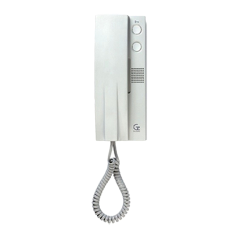
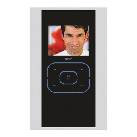
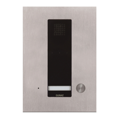
Guinaz M1725V2 User manual

GUÍA DE INSTALACIÓN INSTALLATION GUIDE
KITS DIGITALES
VIDEOPORTERO
DIGITAL VIDEO
ENTRYPHONE KITS

G503130 - R01
ÍNDICE. INDEX.
2
1. Descripción de os equipos. Description of the equip ent..........................................................................................................3
1.1 Descripción p aca ca e. Description of the street panel......................................................................................................3
1.2 Descripción monitor M1725V2. Description of onitor M1725V2..........................................................................................4
1.3 Descripción monitores M3710V2 / M3740V2 / M1717V2E / M1747V2E
Description of onitors M3710V2 / M3740V2 / M1717V2E / M1747V2E..............................................................................4
1.4 Genera idades de sistema digita Guinaz. General properties of the digital syste by Guinaz.............................................5
2. Esquemas de conexión. Connection diagra s...............................................................................................................................6
2.1 Esquema unifi ar y tab a de secciones. Single wire diagra and section table......................................................................6
2.2 Esquema de conexiones para kit de 1 vivienda. Connection diagra s for the kit for 1 dwelling.......................................7
2.3 Esquema de conexiones para kits de más de una vivienda. Connection diagra s for kits for ore than one dwelling......8
2.4 Esquema de conexión con cab e UTP cat.5. Sche atic installation with UTP cat..5 Cable...........................................................9
2.5 Insta ación te éfono sup etorio. Installation of a supple entary telephone.........................................................................10
2.6 Insta ación monitor sup etorio. Installation of a supple entary onitor..........................................................................11
2.7 Conexión de abrepuertas de corriente a terna. Connection of alternating current door openers...................................12
3. Insta ación de os equipos. Installation of the equip ent..........................................................................................................12
3.1 Insta ación p aca ca e. Installation of the street panel.......................................................................................................12
3.2 Co ocación de os tarjeteros. Place ent of na e tags.....................................................................................................13
3.3 Recomendaciones de insta ación de a p aca ca e. Reco endations for street panel installation................................14
3.4 Insta ación fuente de a imentación. Power supply installation...........................................................................................14
3.5 Insta ación base mura y monitor M1725V2. Installation of wall base and onitor M1725V2............................................15
3.6 Insta ación base mura y monitor M3710V2 / M3740V2. Installation of wall base and onitor M3710V2/M3740V2....................15
3.7 Insta ación caja empotrab e y monitor M1717V2E / M1747V2E
Installation of flush ounted box and onitor M1717V2E / M1747V2E...........................................................................16
3.8 Recomendaciones de insta ación de os monitores. Reco endations for the installation of onitors........................17
4. Configuración de os equipos. Configuration of the equip ent..................................................................................................18
4.1 Configuración de grupo contro audio (p aca ca e). Configuration of the audio control group (street panel)................18
4.2 Distribución de a seña de vídeo. Distribution of the video signal....................................................................................18
4.3 Configuración de a te ecámara (p aca ca e). Configuration of the ca era (street panel)..............................................19
4.4 Configuración de microinterruptores en monitores. Configuration of icro-switches in onitors...................................20
4.5 Configuración tarjeta conexiones monitor M1725V2. Configuration of connection card in onitor M1725V2.................20
4.6 Configuración tarjeta conexiones monitores M3710V2, M3740V2, M1717V2E y M1747V2E
Configuration of connection card for onitors M3710V2, M3740V2, M1717V2E and M1747V2E.....................................21
4.7 Módu os pu sadores (p aca ca e): Asignación de códigos de amada
Pushbutton odules (street panel): Call code assignation................................................................................................22
5. Funcionamiento genera . General operating..............................................................................................................................22
5.1 Función de vigi ancia. Surveillance function.....................................................................................................................23
5.2 Bornas 12 y 13: Botón auxi iar AUX. Ter inal blocks 12 and 13: AUX auxiliary button........................................................23
5.3 Borna 16: Segundo botón auxi iar (monitores M3710V2 / M3740V2 / M1717V2E / M1747V2E)
Ter inal block 16: Second auxiliary button ( onitors M3710V2 / M3740V2 / M1717V2E / M1747V2E)...........................23
5.4 Borna ST: Funcionamiento segundo tono (monitores M3710V2 / M3740V2 / M1717V2E / M1747V2E)
ST Ter inal block: Second tone operating ( onitors M3710V2 / M3740V2 / M1717V2E / M1747V2E)............................23
5.5 Regu ación de vo umen de tono de amada (monitores M3710V2 / M3740V2 / M1717V2E / M1747V2E)
Regulation of the call tone volu e ( onitors M3710V2 / M3740V2/ M1717V2E / M1747V2E)........................................24
6. Puesta en marcha y so ución de prob emas. Start-up and proble resolution..........................................................................24

3
1. DESCRIPCIÓN DE LOS EQUIPOS.
DESCRIPTION OF THE EQUIPMENT.
The digital video entryphone syste kits by Guinaz are ade up of
a street panel, onitors, wall bases or flush ounted boxes for the
onitors, a power supply and a direct current door opener. There
are different digital door entry syste kit references according to
several factors such as the type of onitor included, the colour of
the street panel, the nu ber of dwellings, or whether they include
door opener or not. Check the Guinaz product catalogue to choose
the reference that best adapts to your needs and preferences.
The front of the street panel is a co pact panel to which the ca era
odule, the audio control group and the pushbutton odule are
attached. According to the kit odel, this panel is provided in
anthracite grey or in alu iniu colour.
The onitors included in the kits ay be hands-free surface ones
(black and white or colour), surface ones with receiver, or flush
ounted hands-free onitors (black and white or colour). So e kit
odels include onitors with a titaniu -like finish.
The power supply has a 90-264V input voltage range, delivering at
output 17V direct current to supply all the rest of the equip ent in
the installation.
The audio control group of the street panel allows placing an external
pushbutton to activate the door opener. A direct current door opener
(maximum 12Vdc 400mA) or an alternating current door opener
(maximum 12Vac 1A) can be installed in all the digital video
entryphone kits The way these two kits are connected is indicated
below. In the case of kits including a door opener as standard, these
door openers will always use direct current.
These sets of equip ent are for exclusive use in GUINAZ entryphone
installations. They will be installed as specified in this guide while
applying the regulations in force.
Los kits de videoportero digita es de Guinaz constan de p aca ca e,
monitores, bases mura es o cajas de empotrar para os monitores,
fuente de a imentación y abrepuertas de corriente continua. Existen
diferentes referencias de kit de videoportero digita según varios
factores como son e tipo de monitor que incorporan, e co or de
p aca ca e, e número de viviendas, o si inc uyen abrepuertas o no.
Consu te e catá ogo de productos Guinaz para e egir a referencia
que mejor se adapte a sus necesidades y preferencias.
E fronta de a p aca ca e es una p aca compacta en a que van
sujetos e módu o te ecámara, e grupo contro audio y e módu o
pu sadores. Según e mode o de kit, esta p aca se sirve en co or
gris antracita o en co or a uminio.
Los monitores que incorporan os kits pueden ser de superficie manos
ibres (b anco y negro o co or), de superficie co or con auricu ar, o
monitores empotrab es manos ibres (b anco y negro o coor). A gunos
mode os de kit inc uyen monitores en acabado titanio.
La fuente de a imentación posee un rango de tensión de entrada
de 90-264V, y entrega en su sa ida 17V de corriente continua con
os que se a imenta a resto de equipos de a insta ación.
E grupo contro audio de a p aca ca e admite a co ocación de un
pu sador exterior para activar e abrepuertas. En todos os kits de
videoportero digitaes se puede insta ar un abrepuertas de corriente
continua (12Vdc 400mA máximo) o un abrepuertas de corriente
alterna (12Vac 1A máximo). Más ade ante se indica cómo se
conectan os dos tipos. En e caso de os kits que incorporan
abrepuertas de serie, siempre son abrepuertas de corriente continua.
Estos equipos son para uso exc usivo en insta aciones de porteros
GUINAZ. Su insta ación debe rea izarse ta y como se especifica
en esta guía y ap icando a reg amentación vigente.
1. Módulo telecámara: Es e encargado de captar y enviar a imagen a monitor. Hay un mode o para
imagen en b anco y negro, y otro mode o para imagen en co or. Ambos mode os disponen de ajuste
de posición y de i uminación de apoyo. E módu o te ecámara está conectado mediante un atigui o
a grupo contro audio.
Camera module: This is in charge of capturing and sending the i age to the onitor. There is a odel
for black and white i ages and another odel for colour i ages. Both odels have position adjust ent
and support lighting. The ca era odule is connected to the audio control group by eans of a
connector.
2. rupo control audio: Gestiona e funcionamiento de todo e sistema. Está conectado a módu o
te ecámara y a módu o pu sadores mediante atigui os. Con os monitores de as viviendas se conecta
mediante un bus de tres hi os (1M, 2M, 3M), a través de cua se transmiten os datos, a seña de audio
y a a imentación. Para a seña de vídeo se puede insta ar cab e coaxia de 75 ohmios, o cab e tipo
par trenzado cat.5 (100 ohmios). También se puede realizar toda la instalación con un solo cable
UTP cat. 5 (4 pares de hi o trenzado), uti izando un par para cada una de as seña es de sistema
digita Guinaz (vídeo, 1M, 2M, y 3M). E grupo contro audio también genera a seña para a apertura
de abrepuertas. Hay dos mode os de grupo contro audio, según os monitores que incorpore e kit
sean con auricu ar o manos ibres.
Audio control group: This anages the operating of the entire syste . It is connected to the ca era
odule and to the pushbutton odule by eans of connectors. It is connected to the onitors in the
dwellings by eans of a three-wire bus (1M, 2M, 3M), via which the data, the audio signal and the power
supply are trans itted. A 75 oh coaxial cable or a cat.5 twisted pair cable (100 oh s) can be installed
for the video signal. You can also perform the entire installation with a single UTP cable cat 5
(4 twisted pairs), using a pair for each of the digital signals Guinaz (video, 1M, 2M and 3M). The audio
control group also generates the door opening signal. There are two audio control group odels,
according to whether the onitors included in the kit include a receiver or they are hands-free.
3. Módulo pulsadores: Contiene os pu sadores de amada y os tarjeteros de información. Los tarjeteros
están i uminados permanentemente. Está conectado mediante un atigui o a grupo contro audio. Hay
varios mode os de módu os pu sadores según e número de viviendas de kit.
Pushbutton module: This contains the call pushbuttons and the infor ation tags. The tags will be lit
up per anently. They are connected by eans of a connector to the audio control group. There are
several pushbutton odule odels according to the nu ber of dwellings included in the kit.
G503130 - R01
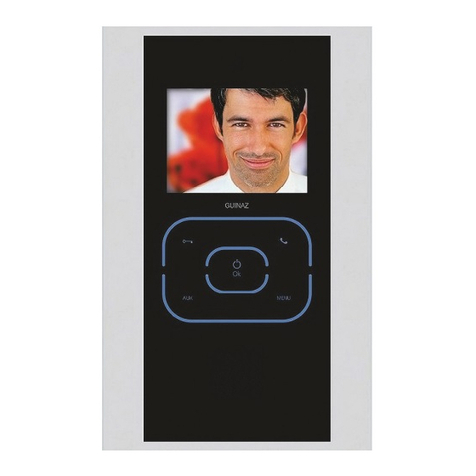
1.1 DESCRIPCIÓN PLACA CALLE.
DESCRIPTION OF THE STREET PANEL.

4
1. Pulsador de encendido/apagado. Uti izado para
conectar y desconectar e monitor.
On/off push-button Used to connect and disconnect
the onitor.
2. Pulsador abrepuertas. Sirve para abrir a puerta.
Door opener push-button This is pressed to open
the door.
3. Pulsador auxiliar. Uti izado para funciones ajenas
a a insta ación de videoportero (i uminación esca era,
apertura segunda puerta....). Contacto ibre de potencia .
Supplementary push-button Used for functions
other than those of the video entryphone installation (lighting
of stairs, opening a second door...). Potential-free contact.
4. Ajuste de brillo. Regu ación de bri o de a imagen
que aparece en panta a.
Brightness adjustment To adjust the brightness of
the i age appearing on the screen.
5. Ajuste de color. Regu ación de co or de a imagen
que aparece en panta a.
Colour adjustment To adjust the colour of the i age
appearing on the screen.
1. Pulsador de encendido/apagado. Uti izado para
conectar y desconectar e monitor.
On/off push-button Used to connect and disconnect
the onitor.
2. Pulsador abrepuertas. Sirve para abrir a puerta.
Door opener push-button This is pressed to open
the door.
3. Pulsador comunicación. Sirve para estab ecer
comunicación audio entre p aca ca e y monitor, siempre
y cuando e monitor se haya encendido previamente.
Communication push-button This is used to
establish audio co unication between the street panel
and the onitor, as long as the onitor has been previously
turned on.
4. Pulsador auxiliar. Uti izado para funciones ajenas
a a insta ación de videoportero (i uminación esca era,
apertura segunda puerta....). Contacto ibre de potencia .
Supplementary push-button Used for functions
other than those of the video entryphone installation (lighting
of stairs, opening a second door...). Potential-free contact.
5. Ajuste de brillo. Regu ación de bri o de a imagen
que aparece en panta a.
Brightness adjustment To adjust the brightness of
the i age appearing on the screen.
5. Ajuste de contraste/color. Regu ación de contraste
o co or de a imagen que aparece en panta a.
Contrasts/Colour adjustment To adjust the
contrasts/colour of the i age appearing on the screen.
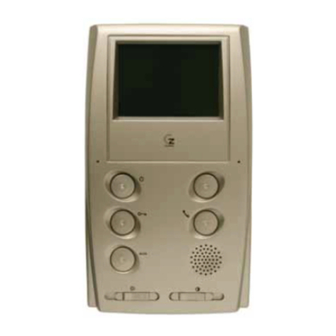
1.2 DESCRIPCIÓN MONITOR M1725V2.
DESCRIPTION OF MONITOR M1725V2.
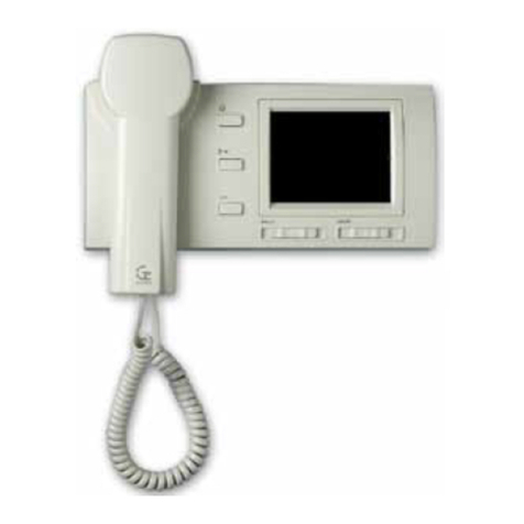
1.3 DESCRIPCIÓN MONITORES M371 V2 / M374 V2 / M1717V2E / M1747V2E.
DESCRIPTION OF MONITORS M371 V2 / M374 V2 / M1717V2E / M1747V2E.
G503130 - R01

5
The cablefor of the digital syste by Guinaz consists of a 3-
wire bus for audio, data and power supply signals, interconnected
with all the equip ent of the installation. There three wires ay
be of any kind readily found on the arket, with one single
require ent: the cross-section of the cables will be
adequate for the installation to be carried out
A 75 oh coaxial cable or a cat.5 twisted pair cable ay be
used for video signal trans ission.
Wire nu ber 1M is positive in the power supply of the equip ent.
Wire nu ber 2M is the ground for the entire digital syste . Wire
nu ber 3M is in charge of transporting the data according to
the digital co unication protocol of the syste and also the
audio signal when co unications are established between
two sets of equip ent.
Wire 1M: power supply +17Vdc
Wire 2M: ground
Wire 3M: co unication (data/audio)
A ong the features of the digital syste by Guinaz are that one
can rely on total secrecy in co unication, the possibility of
perfor ing surveillance fro a dwelling with active audio and
video signal, door opening without the need to call previously,
adjust ent of the tone volu e for onitors, second call tone,
etc.
Simple installations with a single access and more complex
installations with multiple secondary accesses can be
performed with the digital system by Guinaz, without the
need to include additional modules or signal exchanges
between the street panels
E cab eado de sistema digita de Guinaz consiste en un bus
de 3 hi os para as seña es de audio, datos y a imentación, con
os que se interconectan todos os equipos de a insta ación.
Estos tres hi os pueden ser de cua quier tipo de os que
habitua mente se encuentran en e mercado, pero con una única
exigencia: la sección de los cables debe ser la adecuada
para la instalación a realizar.
Para a transmisión de a seña de vídeo se puede uti izar cab e
coaxia de 75 ohmios o cab e par trenzado cat.5.
E hi o número 1M es e positivo de a imentación para os equipos.
E hi o número 2M es a masa de todo e sistema digita . E hi o
número 3M es e encargado de transportar os datos según e
protoco o de comunicación digita de sistema, y también a
seña de audio cuando se estab ece comunicación entre dos
equipos.
Hi o 1M: a imentación +17Vdc
Hi o 2M: masa
Hi o 3M: comunicación (datos/audio)
Entre as prestaciones de sistema digita Guinaz se pueden
contar e secreto tota de comunicación, a posibi idad de hacer
vigi ancia desde una vivienda con seña de audio y vídeo activas,
a apertura de a puerta sin amada previa, regu ación de vo umen
de tono de amada en monitores, segundo tono de amada,
etc.
Con el sistema digital de uinaz se pueden realizar
instalaciones de audio y vídeo sencillas con un único
acceso e instalaciones más complejas con múltiples
accesos secundarios, sin necesidad de incluir módulos
adicionales o intercambiadores de señal entre placas calle.
1.4 GENERALIDADES DEL SISTEMA DIGITAL GUINAZ.
GENERAL PROPERTIES OF THE DIGITAL SYSTEM BY GUINAZ.
G503130 - R01

6
These tables are calculated for one monitor per dwelling
and indicate the maximum distance between the street
panel and the telephones in dwellings according to the
cable cross-section to be installed The axi u distances
for each section will vary in the case of installations with
supple entary onitors or telephones (see points 2.4 and 2.5).
Estas tablas están calculadas para un monitor por vivienda
e indican la distancia máxima entre la placa calle y los
monitores de las viviendas según la sección de cable a
instalar. En e caso de insta aciones con monitores o te éfonos
sup etorios, as distancias máximas para cada sección varían
(consu te os puntos 2.4 y 2.5).
2.1 ESQUEMA UNIFILAR Y TABLA DE SECCIONES.
SINGLE WIRE DIAGRAM AND SECTION TABLE.
2. ESQUEMAS DE CONEXIÓN.
CONNECTION DIAGRAMS.
Conexiones
Connections
1M, 2M, 3M
Secciones (mm²)
Sections (mm²)
Nº de hilos
Nº of wires
3 25 m
Distancias máximas (metros)
Maximum distances (meters)
120 m 180 m60 m
0,22 1 1,50,5
300 m
2,5
Conexiones
Connections
1M, 2M, 3M
Secciones (mm²)
Sections (mm²)
Nº de hilos
Nº of wires
3 50 m
Distancias máximas (metros)
Maximum distances (meters)
230 m 345 m120 m
0,22 1 1,50,5
100 m
UTP cat. 5
TABLA SECCIONES MONITORES BLANCO Y NEGRO.
BLACK & WHITE MONITORS SECTIONS TABLE.
TABLA SECCIONES MONITORES COLOR
COLOUR MONITORS SECTIONS TABLE.
G503130 - R01
50m
UTP cat. 5
575 m
2,5

7
2.2 ESQUEMA DE CONEXIONES PARA KIT DE 1 VIVIENDA.
CONNECTIONS DIAGRAM FOR THE KIT FOR 1 DWELLING.
Abrepuertas (12 Vdc, 400mA máx.)
Door opener (12 Vdc, ax 400 A)
220 Vac
F1334
1
INPUT
2
Pu sador auxi iar abrepuertas
Auxiliary door opener push-button
1M
2M
3M
+12
C
NO
IN
OUT
V/H
M/L
M/L
V/H
-
Para insta ar abrepuertas de a terna véase punto 2.7
Please see point 2.7 to install alternating current door opener
1234
Configuración p aca ca e
Configuration of street panel
P aca principa
Main panel
Conexión mediante atigui os:
Connection with straps:
G1850D - G3250
G3250 - GD211 -
+
MONITOR
V/H
12
M/L
M/L
V/H
13
14
1M
2M
3M
CABLE ALIMENTACIÓN. POWER SUPPLY CABLE.
CABLE SEÑAL. SIGNAL CABLE.
CABLE COAXIAL 75 ohm. 75 Oh COAXIAL CABLE.
Configuración para cab e coaxia
Configuration for coaxial cable
The installation shown above uses coaxial cable for the video
signal. The configuration bridges of the ca era and the wall base
of the onitor ust be changed if cat.5 twisted pair cable is used
to trans it the video signal.
The power supply of the syste is carried out by eans of the
cables joining ter inal blocks 1 and 2 of the power supply with
ter inal blocks 1M and 2M of the audio control group of the street
panel. The co unication bus is for ed by the three cables
leaving ter inal blocks 1M, 2M and 3M of the audio control group
in the street panel, that will be connected to ter inal blocks 1M,
2M and 3M, respectively, of the onitor in the dwelling.
The connection between the street panel and the door opener is
ade using two cables (NO and ter inal blocks of the audio
control group). Terminal blocks +12 and C will connect to
each other by means of a cable An auxiliary external pushbutton
ay be connected between ter inal blocks C and NO in order
to activate the door opener. The ti e the door opener is activated
when the auxiliary external pushbutton is pressed does not have
a ti er, that is to say, it will only re ain active while this external
pushbutton is being pressed.
Se ha representado una instalación con cable coaxial para la
señal de vídeo. Si para la transmisión de la señal de vídeo se
emplea cable tipo par trenzado cat.5, se deben cambiar los
puentes de configuración en la telecámara en la base mural
del monitor.
La alimentación del sistema se realiza mediante los cables que
unen las bornas 1 2 de la fuente de alimentación con las
bornas 1M 2M del grupo control audio de la placa calle. El
bus de comunicación lo forman los tres cables que parten de
las bornas 1M, 2M 3M del grupo control audio de la placa
calle, que se han de conectar a las bornas 1M, 2M 3M,
respectivamente, del monitor de la vivienda.
La conexión entre la placa calle el abrepuertas se realiza
mediante dos cables (bornas NO del grupo control audio).
Las bornas +12 y C deben conectarse entre sí con un
cable. También se puede conectar a las bornas C NO del
grupo control audio un pulsador auxiliar externo para activar
el abrepuertas. El tiempo de activación del abrepuertas cuando
se acciona el pulsador auxiliar externo no está temporizado;
es decir, el abrepuertas sólo está activo mientras se mantiene
pulsado este pulsador externo.
G503130 - R01

8
2.3 ESQUEMA DE CONEXIONES PARA KITS DE MÁS DE UNA VIVIENDA.
CONNECTIONS DIAGRAM FOR KITS FOR MORE THAN ONE DWELLING.
Se ha representado una instaación con cab e coaxia para a seña
de vídeo. Si para a transmisión de a seña de vídeo se emp ea
cab e tipo par trenzado cat.5, se deben cambiar os puentes de
configuración en a te ecámara y en as bases mura es de os
monitores. Así mismo, también deben sustituirse os distribuidores
ref. M1934 por distribuidores ref. M1924. Los distribuidores no
van incluidos en los kit digitales de videoportero.
La a imentación de sistema se rea iza mediante os cab es que
unen as bornas 1 y 2 de a fuente de a imentación con as bornas
1M y 2M de grupo contro audio de a paca ca e. Cada distribuidor
se a imenta desde a borna 14 de os monitores que tiene
conectados a sus sa idas derivadas. Las bornas 14 de los
distribuidores no deben unirse entre sí.
The installation shown above uses coaxial cable for the video
signal. The configuration bridges of the ca era and the wall base
of the onitor ust be changed if cat.5 twisted pair cable is used
to trans it the video signal. Likewise, the ref. M1934 distributors
will be replaced for ref. M1924 distributors. The distributors are
not included in the digital video entryphone kits
The power supply of the syste is carried out by eans of the
cables joining ter inal blocks 1 and 2 of the power supply with
ter inal blocks 1M and 2M of the audio control group of the street
panel. Each distributor is powered by ter inal block 14 of the
onitors connected to its deriving outputs. Terminal blocks 14
of distributors must not be joined to each other
MONITOR n-4
V/H
M/L
M/L
1M
2M
3M
12
13
14
Abrepuertas (12 Vdc, 400mA máx.)
Door opener (12 Vdc, ax 400 A)
Pu sador auxi iar abrepuertas
Auxiliary door opener push-button
+12
C
NO
-
Para insta ar abrepuertas de a terna véase punto 2.7
Please see point 2.7 to install alternating current door opener
-
+
M1934
VMMV
V/H
M4 V4 M1 V1 14
No cortar resistencia
Do no shut-off the resistance
CABLE ALIMENTACIÓN. POWER SUPPLY CABLE.
CABLE SEÑAL. SIGNAL CABLE.
CABLE COAXIAL. COAXIAL CABLE.
V/H
M/L
M/L
V/H
1M
2M
3M
IN
OUT
Configuración p aca ca e
Configuration of street panel
PLACA PRINCIPAL
MAIN PANEL
Conexión mediante atigui os:
Connection with straps:
G1850D - G3250
G3250 - GD2XX
Sucesivamente entre modu os pu sadores
Successively between push button odules
Configuración para
cab e coaxia
Configuration for
coaxial cable
2
1
F1334
MONITOR n
V/H
M/L
M/L
1M
2M
3M
12
13
14
V/H
MONITOR 1
V/H
M/L
M/L
1M
2M
3M
12
13
14
V/H
MONITOR 4
V/H
M/L
M/L
1M
2M
3M
12
13
14
V/H
M1934
M4 V4 M1 V1 14
Cortar resistencia
Shut-off the resistance
VMMV
VMMV
G503130 - R01
220 Vac
INPUT

9
El bus de comunicación lo forman los tres cables que parten de
las bornas 1M, 2M 3M del grupo control audio de la placa calle,
que se han de conectar a las bornas 1M, 2M 3M,
respectivamente, de los monitores de las viviendas.
La conexión entre la placa calle el abrepuertas se realiza
mediante dos cables (bornas NO del grupo control audio).
Las bornas +12 y C deben conectarse entre sí con un cable.
También se puede conectar a las bornas C NO del grupo
control audio un pulsador auxiliar externo para activar el
abrepuertas. El tiempo de activación del abrepuertas cuando se
acciona el pulsador auxiliar externo no está temporizado; es
decir, el abrepuertas sólo está activo mientras se mantiene
pulsado este pulsador externo.
The co unication bus is for ed by the three cables leaving
ter inal blocks 1M, 2M and 3M of the audio control group in the
street panel, which will be connected to ter inal blocks 1M, 2M
and 3M, respectively, of the onitors in the dwellings.
The connection between the street panel and the door opener is
ade using two cables (NO and ter inal blocks of the audio
control group). Terminal blocks +12 and C will connect with
each other by means of a cable
An auxiliary external pushbutton ay also be connected between
ter inal blocks C and NO in order to activate the door opener. The
ti e the door opener is activated when the auxiliary external
pushbutton is pressed does not have a ti er, that is to say, it will
only re ain active while this external pushbutton is being pressed.
G503130 - R01
2.4 ESQUEMA DE CONEXIONES CON CABLE UTP CAT.5.
SCHEMATIC INSTALLATION WITH UTP CAT. 5 CABLE.
MONITOR n-4
V/H
M/L
M/L
1M
2M
3M
12
13
14
Abrepuertas (12 Vdc, 400mA máx.)
Door opener (12 Vdc, ax 400 A)
Pu sador auxi iar abrepuertas
Auxiliary door opener push-button
+12
C
NO
-
Para insta ar abrepuertas de a terna véase punto 2.7.
Please see point 2.7 to install alternating current door opener.
-
+
V/H
UTP Cat. 5
Cab eado Horizonta
Horizontal Wiring
V/H
M/L
M/L
V/H
1M
2M
3M
IN
OUT
Configuración p aca ca e
Configuration of street panel
PLACA PRINCIPAL
MAIN PANEL
Conexión mediante atigui os:
Connection with straps:
G1850D - G3250
G3250 - GD2XX
Sucesivamente entre modu os pu sadores
Successively between push button odules
Configuración para
par trenzado
Configuration for
twisted pair
2
1
F1334
MONITOR n
V/H
M/L
M/L
1M
2M
3M
12
13
14
V/H
J2 (100 ohm)
No cortar resistencia
Do no shut-off the resistance
1M
2M
3M
J2 (100 ohm)
VIDEO VIDEO
UTP Cat. 5
Cab eado Horizonta
Horizontal Wiring
UTP Cat. 5
Cab eado Vertica
Vertical Wiring
MONITOR 1
V/H
M/L
M/L
1M
2M
3M
12
13
14
V/H
MONITOR 4
V/H
M/L
M/L
1M
2M
3M
12
13
14
V/H
J2 (100 ohm)
Cortar resistencia
Shut-off the resistance
J2 (100 ohm)
UTP Cat. 5
Cab eado Vertica
Vertical Wiring
M1924
M4 V4 14 2M1 V1
V/H
M/L
M/L
V/H
1M
2M
3M
VIDEO VIDEO
M1924
M4 V4 14 2M1 V1
V/H
M/L
M/L
V/H
UTP Cat. 5
Cab eado Horizonta
Horizontal Wiring
UTP Cat. 5
Cab eado Horizonta
Horizontal Wiring
220 Vac
INPUT

2.5 INSTALACIÓN TELÉFONO SUPLETORIO.
INSTALLATION OF A SUPPLEMENTARY TELEPHONE.
V/H
12
M/L
M/L
V/H
13
14
1M
2M
3M
1M
2M
3M
12
13
T114 V2
para kits: for kits:
KDV0xx
T1145V2
para kits: for kits:
KDV1xxE
KDV3xxE
KDV4xxE
KDV5xxE
Sup etorio Supple entary
Cab e coaxia 75 ohm
ó par trenzado cat.5.
75 Oh coaxial
or cat. 5 Twisted pair cable.
COAXIAL COAXIAL
J3 (75 ohm)
Par trenzado Twisted pair
J2 (100 ohm)
MONITOR Principa Main
Los microinterruptores del teléfono supletorio se configuran
como sigue:
Los 8 primeros microinterruptores se colocan tal como están
en el monitor, a que el número de vivienda debe ser el
mismo.
El microinterruptor 9 se coloca en la posición ON ® supletorio.
The icro-switches of the supple entary telephone are configured
as follows:
The first 8 icro-switches are placed in the sa e way they are
in the onitor, since the nu ber of dwelling should be the
sa e.
Micro-switch 9 is placed in ON ® supple entary position.
Conexiones
Connections
1M, 2M, 3M
Secciones (mm²)
Sections (mm²)
Nº de hilos
Nº of wires
3
16 m
Distancias máximas (metros)
Maximum distances (meters)
80 m 35 m40 m 1 Monitor + 1 Teléfono Telephone
0,22 1 UTP cat. 50,5
------ 60 m 25 m30 m
------ 40 m 18 m20 m
10
Según la cantidad de teléfonos supletorios instalados, los valores
de las tablas de secciones del punto 2.1 varían. Las tablas
siguientes indican las distancias máximas según la sección de
cable para instalaciones con un monitor más 1, 2 ó 3 teléfonos
supletorios por vivienda:
The values of the section table in point 2.1 will vary according to the
a ount of supple entary telephones installed. The following tables
indicate the axi u distances according to the cable cross-
section for installations with a onitor and 1, 2 or 3 supple entary
telephones per dwelling:
TABLA SECCIONES MONITORES BLANCO Y NEGRO CON TELÉFONOS SUPLETORIOS.
SECTIONS TABLE FOR B&W MONITORS WITH SUPPLEMENTARY TELEPHONES.
120 m
1,5
90 m
60 m
1 Monitor + 2 Teléfonos Telephones
1 Monitor + 3 Teléfonos Telephones
G503130 - R01
E cab e UTP cat. 5 está formado por 4 pares de hi os trenzados y
es un cab e protegido contra interferencias. A rea izarse toda a
insta ación con cab e UTP, resu ta ser una opción barata y fáci de
insta ar.
La distribución de vídeo se reaiza mediente os distribuidores M1924.
En e cab eado vertica , e 3M circu a por un par de UTP, mientras
que e cab eado horizonta o hace por un so o hi o. E otro hi o de
par se uti iza para a imentar e distribuidor de video (borna 14). La
borna 2 de distribuidor (masa) se conecta a par 2M. Recuerde que
as bornas 14 de os dirtribuidores no deben conectarse entre sí.
The UTP cat.5 cable consist of 4 twisted pairs and is protected fro
interference. In aking the entire facility with UTP cable, turns out
to be an option cheap and easy to install.
The distribution of video is ade by distributors M1924. In the vertical
wiring, 3M circulates for one pair of UTP cable, while in the horizontal
wiring does it by a single wire. The other wire of the pair is used to
feed the video distributor (bushing insulator 14). The busing insulator
2 (ground) of the distributor it connects to the pair 2M. Re e ber
that the busing insulators 14 of the distributors should not connect
with each other.
200 m
2,5
150 m
100 m

11
TABLA SECCIONES MONITORES COLOR CON TELÉFONOS SUPLETORIOS.
SECTION TABLE FOR COLOUR MONITORS WITH SUPPLEMENTARY TELEPHONES.
Conexiones
Connections
1M, 2M, 3M
Secciones (mm²)
Sections (mm²)
Nº de hilos
Nº of wires
3
34 m
Distancias máximas (metros)
Maximum distances (meters)
155 m 70 m80 m 1 Monitor + 1 Teléfono Telephone
0,22 1 UTP cat.50,5
25 m 115 m 50 m60 m
16 m 76 m 35 m40 m
230 m
1,5
175 m
115 m
1 Monitor + 2 Teléfonos Telephones
1 Monitor + 3 Teléfonos Telephones
2.6 INSTALACIÓN MONITOR SUPLETORIO.
INSTALLATION OF A SUPPLEMENTARY MONITOR.
V/H
12
M/L
M/L
V/H
13
14
1M
2M
3M
Sup etorio Supple entary
Cab e coaxia 75 ohm
ó par trenzado cat.5.
75 Oh coaxial
or cat. 5 Twisted pair cable.
Principa Main
V/H
12
M/L
M/L
V/H
13
14
1M
2M
3M
COAXIAL COAXIAL
J3 (75 ohm)
Par trenzado Twisted pair
J2 (100 ohm)
MONITOR
J1 (NO )
MONITOR
Los icrointerruptores del onitor supletorio se configuran co o
sigue:
Los 8 pri eros icrointerruptores se colocan tal co o están
en el onitor principal, ya que el nú ero de vivienda debe ser
el is o.
El icrointerruptor 9 se coloca en la posición ON ® supletorio.
Según la cantidad de onitores supletorios instalados, los valores
de las tablas de secciones del punto 2.1 varían. Las tablas siguientes
indican las distancias áxi as según la sección de cable para
instalaciones con un onitor principal ás 1 ó 2 onitores supletorios
por vivienda:
The icro-switches of the supple entary onitor are configured as
follows:
The first 8 icro-switches are placed in the sa e way as in the
ain onitor, since the nu ber of dwelling should be the sa e.
Micro-switch 9 is placed in ON ® supple entary position.
The values of the section table in point 2.1 will vary according to the
a ount of supple entary onitors installed. The following tables
indicate the axi u distances according to the cable cross-section
for installations with a ain onitor and 1, 2 or 3 supple entary
onitors per dwelling:
Conexiones
Connections
1M, 2M, 3M
Secciones (mm²)
Sections (mm²)
Nº de hilos
Nº of wires
3
30 m
Distancias máximas (metros)
Maximum distances (meters)
90 m60 m
1 UTP cat. 50,5
20 m 60 m40 m
TABLA SECCIONES MONITORES BLANCO Y NEGRO CON MONITORES SUPLETORIOS.
SECTION TABLE FOR B&W MONITORS WITH SUPPLEMENTARY MONITORS.
25 m
1,5
18 m
1 Principa Main + 1 Supletorio Supple entary
1 Principa Main + 2 Supletorios Supple entary
G503130 - R01
385 m
2,5
290 m
192 m
2,5
150 m
100 m

TABLA SECCIONES MONITORES COLOR CON MONITORES SUPLETORIOS.
SECTION TABLE FOR COLOUR MONITORS WITH SUPPLEMENTARY MONITORS.
Conexiones
Connections
1M, 2M, 3M
Secciones (mm²)
Sections (mm²)
Nº de hilos
Nº of wires
325 m
Distancias máximas (metros)
Maximum distances (meters)
115 m 50 m60 m
0,22 1 UTP cat. 50,5
------ 76 m 35 m40 m
175 m
1,5
115 m
Todos los kit de vídeo digitales ad iten la conexión de un abrepuertas
de corriente alterna. La conexión entre la placa calle y el abrepuertas
se realiza de for a diferente y es preciso añadir una fuente de
ali entación F1318. Con esta configuración se pueden activar
abrepuertas de corriente alterna de 12Vac y 1A de corriente áxi a.
El esque a ostrado a continuación detalla la conexión entre el
grupo control audio digital de la placa calle, la fuente de ali entación
F1318 y el abrepuertas de corriente alterna:
All the digital video kits allow the connection of an alternating current
door opener. The connection between the street panel and the door
opener is carried out in a different anner, it being necessary to
add a F1318 power supply. 12Vac alternating current with a axi u
current of 1A can be activated with this configuration.
The diagra shown below provides details on the connection
between the digital audio control group of the street panel, power
supply F1318 and the alternating current door opener:
2.7 CONEXIÓN DE ABREPUERTAS DE CORRIENTE ALTERNA.
CONNECTION OF ALTERNATING CURRENT DOOR OPENERS.
The ti e the door opener is activated when the auxiliary external
pushbutton is pressed does not have a ti er, that is to say, it will
only re ain active while this external pushbutton is being pressed.
12
220 Vac
F1318
PRIM
Abrepuertas de corriente a terna (12 Vac, 1A máx.)
Alternating current door opener (12 Vac, ax 1A)
Pu sador auxi iar abrepuertas
Auxiliary door opener push-button
+12
C
NO
-
1
2
E tiempo de activación de abrepuertas cuando se acciona e
pu sador auxi iar externo no está temporizado; es decir, e abrepuertas
só o está activo mientras se mantiene pu sado este pu sador
externo.
3.1 INSTALACIÓN PLACA CALLE.
INSTALLATION OF THE STREET PANEL.
3. INSTALACIÓN DE LOS EQUIPOS.
INSTALLATION OF THE EQUIPMENT.
1Sujete a p aca ca e
mediante dos torni os.
Attach the street panel
using two screws.
Para apertura a la derecha. To open towards the right
A. Sue te e torni o izquierdo y af oje e derecho. Unscrew left
screw and loosen the right one.
B. Desp ace a p aca ca e hacia a izquierda y fronta mente 1,5
mm. Move the street panel 1.5 to the left and the front.
C. Gire a p aca ca e. Open the street panel.
Co oque a caja
empotrab e.
Asse bly the flush
ounted box.
23
1 Principa Main + 1 Supletorio Supple entary
1 Principa Main + 2 Supletorios Supple entary
290 m
2,5
192 m
G503130 - R01

13
Ajuste e vo umen de audio en p aca ca e y vivienda.
Adjust the audio volu e in the street panel and the
dwelling.
IMPORTANTE: COLOCAR LAS
TAPAS SUPERIOR E INFERIOR
ANTES DE CERRAR LA PLACA
CALLE. PRESIONAR HASTA OÍR EL
CLIP.
IMPORTANT: CLIP ON THE LOWER
AND UPPER COVERS BEFORE
CLOSING THE STREET PANEL.
PRESS UNTIL THEY CLIP IN.
Cierre a p aca de ca e
apretando ambos
torni os.
Close the street panel
by tightening both
screws.
Conecte os cab es a
grupo contro audio.
Configure a p aca ca e
(véase punto 4.1).
Connect the cables to
the audio control group.
Configure the street
panel (see point 4.1).
5
79
4
ONCE THE STREET PANEL IS INSTALLED, REMEMBER:
TO OPEN THE STREET PANEL IT IS NOT NECESSARY
TO REMOVE THE UPPER AND LOWER COVERS It is
only necessary to unscrew one screw and to loosen the
other (see sections 3 and 4).
THE UPPER AND LOWER COVERS CAN ONLY BE FITTED
IN OR REMOVED WITH THE STREET PANEL OPEN
Once this is closed, the anchoring clips of the covers are
left trapped by the panel itself in order to avoid actions of
vandalis .
UNA VEZ INSTALADA LA PLACA CALLE, RECUERDE QUE:
PARA ABRIR LA PLACA CALLE NO HAY QUE QUITAR
LAS TAPAS SUPERIOR E INFERIOR. Só o es necesario
so tar un torni o y af ojar e otro (consu te os apartados 3
y 4).
LAS TAPAS SUPERIOR E INFERIOR SÓLO PUEDEN
PONERSE O QUITARSE CON LA PLACA CALLE
ABIERTA. Una vez cerrada ésta, as pati as de anc aje de
as tapas quedan atrapadas por a propia p aca para evitar
acciones vandá icas.
3.2 COLOCACIÓN DE LOS TARJETEROS.
PLACEMENT OF NAME TAGS.
Extracción de tarjetero de
módu o de pu sadores
co ocado en p aca ca e.
Extract the na e card unit
fro the push-button
odule of the street panel.
Separar trans úcido de
crista .Separate
translucent glass part.
Introducción de tarjetero.
Insert the card.
Insertar en módu o de
pu sadores hasta c ipar.
Insert in the push-button
odule until it clips in.
1234
Para apertura a la izquierda. To open towards the left
A. Sue te e torni o derecho y af oje e izquierdo. Unscrew right
screw and loosen the left one.
B. Desp ace a p aca ca e hacia a derecha y fronta mente 1,5
mm. Move the street panel 1.5 to the right and the front.
C. Gire a p aca ca e. Open the street panel.
Ajuste a posición de a
te ecámara y configure
os puentes según e
tipo de cab e insta ado
(véase punto 4.3).
Adjust the position of the
ca era and configure
the bridges according
to the type of cable
installed(see point 4.3).
6
8
G503130 - R01

14
La p aca de ca e está suficientemente protegida
de as condiciones atmosféricas. Sin embargo, es
conveniente insta ar a en un ugar en que no afecten
directamente agentes como a uvia, humedad, etc.
Cuando a p aca ca e esté expuesta a a intemperie,
se recomienda insta ar a sobre un marco visera. En
e caso de superficies no isas, donde a p aca ca e
o e marco visera no queden perfectamente se ados
mediante as juntas que incorporan, se recomienda
ap icar a gún se ante en toda a parte superior de
a p aca ca e o marco visera para evitar entradas
de agua que puedan dañar e equipo.
The street panel is sufficiently protected against
at ospheric conditions. However, it is
reco endable to install it in a place where agents
such as rain, hu idity, etc. cannot affect it.
When the street panel is exposed to the ele ents
it is reco endable to install it with a visor fra e.
In the case of surfaces that are not s ooth, where
the street panel or visor fra e are not perfectly
sealed with the joints that are incorporated, then
so e sort of sealer should be applied throughout
the entire upper part of the street panel or visor
fra e to thus avoid water fro penetrating and
da aging the equip ent.
3.3 RECOMENDACIONES DE INSTALACIÓN DE LA PLACA CALLE.
RECOMMENDATIONS FOR STREET PANEL INSTALLATION.
La manipu ación interna de os equipos só o puede rea izarse por persona especia izado, y siempre con e equipo desconectado
de a a imentación.
Internal handling of the equip ent ay only be perfor ed by specialised personnel, always once the equip ent has been disconnected
fro the power supply.
En a insta ación de videoportero, se ha
de escoger un ugar donde no incida
directamente una fuente de uz (so ,
faro as, etc.) sobre a te ecámara, para
evitar e efecto de contra uz en a imagen.
En e caso de que a imagen no sea nítida
debido a uz insuficiente para a
te ecámara, se ha de co ocar una
i uminación auxi iar como se indica en a
figura. Esta i uminación auxi iar puede
insta arse de ta forma que só o se i umine
a escena cuando haya un monitor
funcionando.
When choosing the location to install a
video door entry syste it is i portant to
find a location where the source of light
(sun, street la ps, etc.) does not directly
affect the ca era, to thus avoid the effect
of the back light on the i age.
If the i age is not clear and sharp due
to a lack of light for ca era, then auxiliary
lighting should be placed as is duly
indicated in the figure. This auxiliary
lighting can be installed in such a way
that it only lights up the scene when a
onitor is working.
3.4 INSTALACIÓN FUENTE DE ALIMENTACIÓN.
POWER SUPPLY INSTALLATION.
A. La fuente de a imentación puede insta arse sobre carri
DIN o mediante tirafondos a a pared, pero siempre en
interiores. The power supply can be installed on a DIN slide
or by eans of sleeper-screws into the wall, always internally.
Rea ice as conexiones según esquema e éctrico y
atorni e e protector de bornas.
Perfor the connections according to the electricity
diagra and screw in the ter inal.
12
G503130 - R00

15
Configure a tarjeta de conexiones de a base mura según
se indica en os puntos 4.4 y 4.6, y conecte e atigui o de
monitor.
Configure the connection card of the wall base as indicated
in points 4.4 and 4.6, and connect the connector of the
onitor.
1Co ocar a base mura en a pared mediante cuatro
tirafondos y conectar tarjeta de conexiones.
Asse ble this wall base panel on the wall using four
sleeper-screws and connect it to the connection card.
2
3.5 INSTALACIÓN BASE MURAL Y MONITOR M1725V2.
INSTALLATION OF WALL BASE AND MONITOR M1725V2
Co oque a base mura en pared mediante cuatro tirafondos
y conecte os cab es a a tarjeta de conexiones.
Asse ble the wall base on the wall using four sleeper-
screws and connect the cables to the connection card.
1Configure a tarjeta de conexiones de a base mura según
se indica en os puntos 4.4 y 4.5, y conecte e atigui o de
monitor.
Configure the connection card of the wall base as indicated
in points 4.4 and 4.5, and connect the connector of the
onitor.
2
34
5
Co ocación de monitor:
A) Encaje e monitor sobre a base
mura .
B) Presione hacia abajo hasta oír e
c ip.
Placing the onitor:
A) Fit in the onitor onto the wall
base.
B) Press downwards until it clips in.
Conecte e auricu ar a
monitor.
Connect the receiver to
the onitor.
Para separar e monitor de a base mura :
A) Sue te e c ip con un destorni ador
B) Empuje hacia arriba y uego hacia
fuera.
To separate the onitor fro the wall
base:
A) Unclip with a screwdriver
B) Push up and then outwards
3.6 INSTALACIÓN BASE MURAL Y MONITOR M371 V2 / M374 V2.
INSTALLATION OF WALL BASE AND MONITOR M371 V2 / M374 V2.
¡ATENCIÓN!¡IMPORTANTE!
OBSERVE QUE LA POSICIÓN DE MONTAJE DE LAS BASES MURALES DE LOS MONITORES M3710V2 (B/N) Y M3740V2
(COLOR) ES DIFERENTE.
WARNING! IMPORTANT!
IT SHOULD BE OBSERVED THE ASSEMBLY POSITION OF THE WALL BASES IS DIFFERENT FOR MONITORS M3710V2 (B&W)
AND M3740V2 (COLOUR).
G503130 - R01

16
Empotrar caja para monitor empotrab e. E canto de a caja debe quedar a ras de pared.
Fit in the box for the flush ounted onitor. The edge of the box will be at the level of the wall.
¡ATENCIÓN! ¡IMPORTANTE!
LA POSICIÓN DE MONTAJE DE LAS CAJAS DE LOS MONITORES M1717V2E (B&N) Y M1747V2E (COLOR) ES DIFERENTE.
WARNING! IMPORTANT!
THE ASSEMBLY POSITION FOR MONITOR M1717V2E (B&W) IS DIFFERENT FROM THAT FOR M1747V2E (COLOUR).
1
Conectar os cab es y configurar a tarjeta de conexiones
según se indica en os puntos 4.4 y 4.6.
Perfor the connections and configure card connections
as indicated in points 4.4 and 4.6.
2Antes de co ocar e monitor ajustar as pati as des izantes,
de ta forma que as superficies de referencia indicadas
queden a ras de a pared. Cuando estas superficies queden
nive adas, sujetar as pati as con os torni os de apriete.
Before installing the onitor, adjust the sliding strips in such
a way that the reference surfaces are at wall level. Once
levelled, tighten the strips with the screws for tightening.
3
5
4Co ocación monitor:
A) Encajar sobre base mura .
B) Presionar hasta c ipar.
Asse bly of the onitor
A) Asse ble on the wall base.
B) Press down until it clips in.
Para separar monitor:
A) So tar e c ip con un destorni ador.
B) Empujar hacia arriba y uego hacia fuera.
Disasse bly of the onitor
A) Unclip with a screwdriver.
B) Move up and then outwards.
3.7 INSTALACIÓN CAJA EMPOTRABLE Y MONITOR M1717V2E / M1747V2E.
INSTALLATION OF FLUSH MOUNTED BOX AND MONITOR M1717V2E /
M1747V2E.
G503130 - R01

17
Antes de introducir e monitor en a caja, conectar e atigui o
de monitor:
A) Introducir e monitor en a caja empotrab e.
B) Desp azar atera mente, centrando e monitor.
Connect the connector before inserting the onitor in the box:
A) Fit the onitor in the flush ounted box.
B) Move the onitor sideways to centre it.
4Una vez co ocado e monitor y nive ado vertica mente,
apretar os dos torni os ocu tos en a carcasa de
monitor.
Once the onitor has been installed and levelled
vertically, tighten the two screws hidden in the onitor
casing.
5
Los monitores son para uso exc usivo en insta aciones de porteros
y videoporteros GUINAZ. Su insta ación debe rea izarse ta y
como se especifica en esta guía y ap icando a reg amentación
vigente.
La manipu ación interna de estos productos só o puede rea izarse
por persona especia izado, y siempre con e equipo desconectado
de a a imentación.
Mantenga siempre despejadas as ranuras de venti ación de os
monitores; en ningún caso pueden quedar obstruidas o tapadas.
Los monitores están diseñados para ser insta ados en interiores;
no se han de exponer a gotas o proyecciones de agua.
Se recomienda insta ar os monitores en ugares desde os cua es
se escuche a amada en toda a vivienda, y que estén a ejados
de fuentes de ca or (radiadores, estufas, etc.) o de ambientes
agresivos (cocinas, etc.).
3.8 RECOMENDACIONES DE INSTALACIÓN DE LOS MONITORES.
RECOMMENDATIONS FOR THE INSTALLATION OF MONITORS.
These onitors are for exclusive use with GUINAZ entryphone
and video entryphone installations. They will be installed as
specified in this guide while applying the regulations in force.
Internal handling of the equip ent ay only be perfor ed by
specialised personnel, always once the equip ent has been
disconnected fro the power supply.
Always keep the ventilation grills of the onitors clear; they ust
never be obstructed or covered. The onitors are designed to
be installed internally; they ust not be exposed to raindrops or
splashing water.
Installing the onitors in places where calls can be heard all
around the dwelling and far fro heat sources (radiators, heaters,
etc.) or aggressive environ ents (kitchens, etc.) is reco ended.
G503130 - R01

18
4.1 CONFIGURACIÓN DEL GRUPO CONTROL AUDIO (PLACA CALLE).
CONFIGURATION OF THE AUDIO CONTROL GROUP (STREET PANEL).
4. CONFIGURACIÓN DE LOS EQUIPOS.
CONFIGURATION OF THE EQUIPMENT.
En a siguiente tab a se deta a a re ación entre as posib es configuraciones de os microinterruptores y e va or numérico que representa
cada una de e as.
The following table gives details on the possible configurations of icro-switches and the nu ber value represented by each of these.
0 PRINCIPAL MAIN
1 SECUNDARIA Nº 1 SECONDARY NUM. 1
2 SECUNDARIA Nº 2 SECONDARY NUM. 2
3 SECUNDARIA Nº 3 SECONDARY NUM. 3
4 SECUNDARIA Nº 4 SECONDARY NUM. 4
5 SECUNDARIA Nº 5 SECONDARY NUM. 5
6 SECUNDARIA Nº 6 SECONDARY NUM. 6
7 SECUNDARIA Nº 7 SECONDARY NUM. 7
8 SECUNDARIA Nº 8 SECONDARY NUM. 8
9 SECUNDARIA Nº 9 SECONDARY NUM. 9
10 SECUNDARIA Nº 10 SECONDARY NUM. 10
11 SECUNDARIA Nº 11 SECONDARY NUM. 11
12 SECUNDARIA Nº 12 SECONDARY NUM. 12
13 SECUNDARIA Nº 13 SECONDARY NUM. 13
14 SECUNDARIA Nº 14 SECONDARY NUM. 14
15 SECUNDARIA Nº 15 SECONDARY NUM. 15
4.2 DISTRIBUCIÓN DE LA SEÑAL DE VÍDEO.
DISTRIBUTION OF THE VIDEO SIGNAL
La seña de vídeo se puede distribuir tanto con cab e coaxia de
75 ohmios como con cab e par trenzado de categoría 5 (100
ohmios). Si bien as instaaciones para ambos cab es son simiares,
existen a gunas diferencias a tener en cuenta:
La resistencia de terminación de ínea es de diferente va or:
75 ohmios para cab e coaxia y 100 ohmios para par trenzado.
Por defecto, os monitores están configurados mediante un
puente con a resistencia correspondiente a cab e coaxia
(75 ohmios).
La configuración por defecto de as te ecámaras también es
para cab e coaxia (75 ohmios). En e punto 4.3 se indica
cómo configurar os puentes de as te ecámaras según e
tipo de cab e insta ado.
The video signal can be distributed both via a 75 oh coaxial
cable and with a category 5 twisted pair cable (100 oh s). Although
the installations for both cables are si ilar, there are so e
differences to be taken into account:
The line-end resistance has different values: 75 oh s for
coaxial cable and 100 oh s for twisted pair cable. The
onitors will be configured by default by eans of a bridge
with the resistance correponding to the coaxial cable (75
oh s).
The default configuration for ca eras will also be that for
coaxial cable (75 oh s). Point 4.3 shows how to configure
the ca era bridges according to the type of cable installed.
G503130 - R01
E grupo contro audio insta ado en a p aca ca e posee un grupo
de 4 microinterruptores. Los cuatro microinterruptores van
configurados de serie en a posición OFF (número cero placa
calle principal). En caso de añadir accesos secundarios a a
insta ación, as p acas ca e añadidas deben configurarse de
forma corre ativa (1, 2, 3, ... placas calle secundarias).
Sólo un acceso debe estar configurado como principal. E
número máximo de accesos secundarios que se pueden añadir
es 15.
The audio control group installed in the street panel has a group
of 4 icro-switches. All four icro-switches are configured in OFF
position as standard (number zero main street panel) In the
case of adding secondary accesses to the installation, the street
panels added will be configured in a correlative anner (1, 2, 3,
secondary street panels) Only one access will be
configured as being the main one 15 will be the axi u
nu ber of secondary accesses that can be added.

19
Los distribuidores de vídeo son diferentes según se insta e
cab e coaxia o par trenzado. Los distribuidores de seña de vídeo
no van inc uidos en os kit digita es.
IMPORTANTE: En instalaciones con accesos secundarios,
el cable de vídeo parte desde la placa calle principal y
recorre en serie las placas calle de los accesos secundarios,
y desde el último de estos accesos sube hacia las viviendas.
Los distribuidores se a imentan de forma diferente, según e tipo
de cab e uti izado:
Desde los monitores en instalaciones con cable coaxial:
mediante un cab e desde a sa ida de a imentación para
distribuidores (borna 14) de cada uno de os monitores
conectados a as sa idas derivadas de distribuidor.
Desde los monitores en instalaciones con par trenzado:
además de cab e indicado en e primer punto, también hay
que conectar a distribuidor e cab e número 2M de bus
digita .
En ambos casos, e distribuidor só o recibe a imentación cuando
uno de os monitores conectados a é está en funcionamiento.
Todos os distribuidores evan incorporada una resistencia de
terminación de ínea, que se ha de cortar si e distribuidor no es
e ú timo de su rama de distribución; es decir, e cab e de vídeo
entra a distribuidor y sa e hacia otro distribuidor o monitor desde
su sa ida directa (no confundir a sa ida directa de distribuidor
con sus sa idas derivadas).
Video distributors will be different depending on whether coaxial
or twisted pair cable is installed. Video signal distributors are not
included in the digital kits.
IMPORTANT: in installations with secondary accesses, the
video cable starts from the main street panel and runs along
the street panel of the secondary in series, going up to the
dwellings from the last one of these accesses
The distributors are powered differently according to the type of
cable used:
From monitors in installations with coaxial cable: by
eans of a cable fro the power output for distributors
(ter inal block 14) of each of the onitors connected to the
outputs deriving fro the distributor.
From monitors in installations with twisted pair cable:
apart fro the cable indicated in the point above, cable
nu ber 2M of the digital bus will also be connected to the
distributor.
In either case, the distributor will only receive power supply when
one of the onitors connected to it is working.
All distributors include a line-end resistance, that will be cut off if
the distributor is not the last along its distribution branch; that is
to say, the video cable enters the distributor and exits towards
another distributor or onitor fro its direct output (the direct
output of the distributor should not be istaken for its deriving
outputs).
4.3 CONFIGURACIÓN DE LA TELECÁMARA (PLACA CALLE).
CONFIGURATION OF THE CAMERA (STREET PANEL).
Las te ecámaras poseen tres puentes que se han de configurar
según se insta e cab e coaxia (75 ohmios) o par trenzado cat.5
(100 ohmios) para a transmisión de a seña de vídeo. Por defecto,
os puentes van co ocados de fábrica en a posición para cab e
coaxia (75 ohmios).
Ca eras have three bridges to be configured according to whether
coaxial cable (75 oh s) or cat.5 twisted pair cable (100 oh s)
is installed for the trans ission of the video signal. By default, the
bridges co e in coaxial cable (75 oh s) position as standard.
Configuración puentes para insta aciones con cab e de vídeo coaxia 75 ohmios.
Configuration of the ju pers for installations with 75 oh coaxial cable.
Configuración puentes para insta aciones con cab e par trenzado cat.5 (100 ohmios).
Configuration of the ju pers for installations with Cat. 5 (100 oh ) twisted pair cable.
G503130 - R01

20
The connection card of each onitor wall base or flush ounted
box has a group of nine icro-switches. The first eight icro-
switches will be configured with the dwelling nu ber associated
to the onitor. Micro-switch nu ber 9 configures the onitor for
this to be the ain or a supple entary one. If ore than one
onitor (or supple entary telephones) is installed per dwelling,
they will all be configured with the sa e dwelling nu ber and,
also, one and only one of the will be configured as being the
ain one and the rest as supple entary ones.
La tarjeta de conexiones de cada base mura o caja empotrab e
de monitor posee un grupo de nueve microinterruptores. Los
ocho primeros microinterruptores configuran e número de vivienda
asignado a monitor. E microinterruptor número 9 configura e
monitor como principa o como sup etorio. Si se insta a más de
un monitor (o te éfonos sup etorios) por vivienda, todos e os
deben configurarse con e mismo número de vivienda, y, además,
uno de e os y só o uno se deberá configurar como principa y
e resto como sup etorios.
4.4 CONFIGURACIÓN DE MICROINTERRUPTORES EN MONITORES.
CONFIGURATION OF MICRO-SWITCHES IN MONITORS.
The following figure shows the function of the ter inal blocks in
the connection card of the wall base for onitor M1725V2:
The connection card has a 75 oh (R1) resistance asse bled
as standard at the end of the video line. The kit supplies a 100
oh resistance. The following will be carried out according to the
cable installed and the position of the onitor along the video line:
In video installations using 75 oh coaxial cable and with the
onitor being the last along its distribution line (the video
cable only enters the card), there is no need to change the
75 oh resistance that co es in position R1 of the connection
card as standard.
In video installations using cat.5 Twisted pair cable (100 oh s)
and with the onitor being the last along its distribution line
(the video cable only enters the card), the 75 oh resistance
in position R1 has to be cut off and the 100 oh resistance,
provided in the kit, will be fitted in ter inal blocks M/L and
V/H of the connection card.
La siguiente figura muestra a funciona idad de as bornas de a
tarjeta de conexiones de a base mura para monitor M1725V2:
La tarjeta de conexiones eva montada de serie una resistencia
de 75 ohmios (R1) como fina de ínea de vídeo. En e kit se
suministra una resistencia de 100 ohmios. Según e cab e instaado
y a posición de monitor en a ínea de vídeo, se deberá rea izar
o siguiente:
En insta aciones de vídeo con cab e coaxia 75 ohmios y
siendo e monitor e ú timo de su rama de distribución (e
cab e de vídeo só o entra a a tarjeta), no hay que tocar a
resistencia de 75 ohmios co ocada de fabrica en a posición
R1 de a tarjeta de conexiones.
En insta aciones de vídeo con cab e par trenzado cat.5 (100
ohmios) y siendo e monitor e ú timo de su rama de
distribución (e cab e de vídeo só o entra a a tarjeta), hay
que cortar a resistencia de 75 ohmios co ocada en a posición
R1, y co ocar a resistencia de 100 ohmios, que se sirve con
e kit, en as bornas ibres M/L y V/H de a tarjeta de conexiones.
Coaxia o Par trenzado.
Coaxial or Twisted pair.
A imentación distribuidor de vídeo.
Distributor power supply.
Pu sador auxi iar (17Vmáx, 40mA máx).
Supple entary pushbutton ( ax 17V, ax 40 A).
M1725V2
BUS
V/H
12
M/L
M/L
V/H
13
14
1M
2M
3M
1M 2M 3M
4.5 CONFIGURACIÓN TARJETA CONEXIONES MONITOR M1725V2.
CONFIGURATION OF CONNECTION CARD IN MONITOR M1725V2.
G503130 - R01
This manual suits for next models
4
Table of contents
Other Guinaz Intercom System manuals

Guinaz
Guinaz 1140V2 User manual

Guinaz
Guinaz T1140V2 User manual

Guinaz
Guinaz PDV501SIP User manual

Guinaz
Guinaz PDV501SIP User manual

Guinaz
Guinaz GD0501 User manual

Guinaz
Guinaz M3760 User manual

Guinaz
Guinaz A2410 User manual

Guinaz
Guinaz M2710D User manual

Guinaz
Guinaz M3750 User manual

Guinaz
Guinaz T1150 User manual