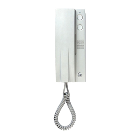
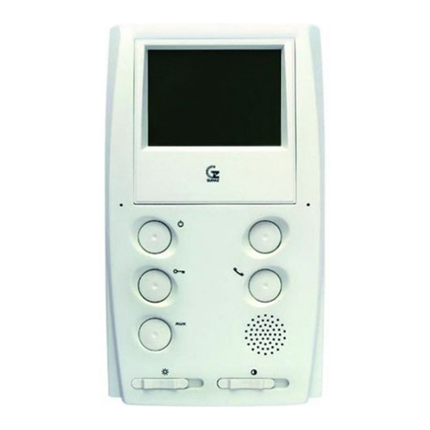
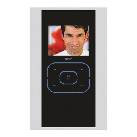
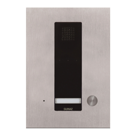
Guinaz M2710D User manual

GUÍA DE INSTALACIÓN INSTALLATION GUIDE
SISTEMA MODULAR
VIDEOPORTERO DUAL
MANOS LIBRES
MODULAR DUAL
HANDS-FREE VIDEO
ENTRYPHONE SYSTEM

G5031133 - R00
CARACTERÍSTICAS Y FUNCIONAMIENTO. CHARACTERISTICS AND FUNCTIONING.
2
1. Pulsador de encendido/apagado. Utilizado ara conectar y desconectar el monitor.
On/off push-button. Used to connect and disconnect the monito .
2. Pulsador abrepuertas. Sirve ara abrir la uerta.
Door opener push-button. This is p essed to open the doo .
3. Pulsador comunicación. Sirve para establecer comunicación audio entre placa
calle y monitor, siempre y cuando el monitor se haya encendido previamente.
Communication pushbutton. This is used to establish audio communication between
the st eet panel and the monito , as long as the monito has been p eviously tu ned on.
4. Pulsador auxiliar. Utilizado ara funciones ajenas a la instalación del video ortero
(iluminación escalera, a ertura segunda uerta....). Contacto libre de otencial.
Supplementary push-button. Used fo functions othe than those of the video
ent yphone installation (lighting of stai s, opening a second doo ...). Potential-f ee contact.
5. Ajuste de brillo. Regulación del brillo de la imagen que a arece en antalla.
Brightness adjustment. To adjust the b ightness of the image appea ing on the sc een.
6. Ajuste de contraste/color . Regulación de contraste o color de la imagen que a arece
en antalla.
Contrasts/Colour adjustment . To adjust the cont ast/colou of the image appea ing
on the sc een.
DESCRIPCIÓN. DESCRIPTION.
Instalación de video ortero (blanco y negro o color) ara varias
viviendas con confirmación de llamada en laca calle y
autoencendido del monitor.
El funcionamiento y la instalación son sencillos.
Los asos de la instalación vienen reflejados en los diferentes
a artados, dis oniendo en laca de calle de varios ajustes ara
cada ti o de instalación, tales como la osición de la telecámara,
el volumen del sonido, etc.
El monitor también dis one de ajustes en la imagen ara así
adecuar ésta a las exigencias y carencias de luz.
El ti o de cableado es el ya conocido de 5 + n + cable coaxial
o ar trenzado ara la señal de vídeo, donde "n" es el número
de llamadas.
Su funcionamiento, es el siguiente:
1. Al recibir una llamada, la imagen a arece instantáneamente
en su monitor.
2. Mientras usted visualiza la visita, ésta no advierte su resencia
en la vivienda hasta que no establece contacto auditivo .
3. Para establecer contacto auditivo ulse el botón de
comunicación . Para oder activar audio, el monitor ha
de estar ya encendido, ya sea or llamada o or
videovigilancia. No es necesario mantener ulsado el botón
de comunicación una vez iniciada esta.
4. La comunicación se desconectará una vez transcurridos
40 seg. desde que se inició, o ulsando el botón de
encendido/a agado .
5. La a ertura de la uerta se realiza mediante el ulsador
de abre uertas .
6. Para realizar videovigilancia, ulsar el botón de
encendido/a agado . La videovigilancia finalizará
automáticamente a los 40 seg. de iniciada, o ulsando de
nuevo el botón de encendido/a agado .
7. Para otras a licaciones, cuenta con un ulsador auxiliar
libre de otencial.
8. Para conseguir una adecuada calidad de imagen dis one
de ajuste de brillo y contraste/color .
A lo largo de este folleto, se le informará de cómo realizar
reformas, tales como añadir otros teléfonos y monitores
su letorios, o incluso la manera más fácil de distribuir la señal
de vídeo.
Video ent yphone (black and white o colou ) installation fo
seve al dwellings with call confi mation in the st eet panel and
automatic sta t-up of the monito .
Its functioning and installation a e simple.
The steps fo installation a e shown in the diffe ent sections,
with a st eet panel offe ing seve al adjustments fo each type
of installation, such as the position of the came a, sound volume,
etc.
The monito also p ovides image adjustments to adapt this to
light equi ements and the lack of light.
The type of installation is that known as 5 + n + coaxial cable
o twisted pai fo the video signal, whe e n is the numbe of
calls.
It wo ks in the following way:
1. When eceiving a call, the image appea s instantly on you
monito .
2. While you see the visito s, these a e not wa ned about you
p esence in the dwelling until audio contact is established.
3. To establish audio contact p ess the communication button
. The monito must be on, due to a call o video
su veillance, fo audio to be activated. It will not be necessa y
to keep communication button p essed down once this
has commenced.
4. The communication will be disconnected afte 40 seconds,
o by p essing the on/off button .
5. The doo is opened by p essing the doo opene pushbutton
.
6. To pe fo m video su veillance, p ess the on/off button .
Video su veillance will automatically end 40 seconds afte
it is initiated, o by once again p essing the on/off button
.
7. Fo othe applications it has a supplementa y potential-f ee
pushbutton .
8. It has b ightness and cont ast/colou adjustments to
achieve an app op iate image quality.
In this guide, you will be info med on how to pe fo m alte ations,
such as adding othe supplementa y telephones and monito s
o even the easiest way of dist ibuting the video signal.

3
G503133 - R00
1Coloque la caja
em otrable.
Assembly the flush
mounted box.
Se are las ta as, destornille ambos tornillos
y extraiga las juntas de módulos.
Sepa ate the cove s, loosen both sc ews and
ext act the joints of the modules.
Introduzca los módulos y juntas en el
mismo orden que a arecen en la figura.
Inse t modules and joints in the same o de
as in the figu e.
23
INSTALACIÓN PLACA CALLE. INSTALLATION OF THE STREET PANEL.
456
Sujete la laca calle
mediante dos
tornillos. Attach the
st eet panel using
two sc ews.
Coloque el marco su erior
y a riete ambos tornillos.
Put the uppe f ame in
place and tighten both
sc ews.
Para apertura a la derecha. To open to ards the right.
A. Suelte el tornillo izquierdo y afloje el derecho. Unsc ew
left sc ew and loosen the ight one.
B. Des lace la laca calle hacia la izquierda y frontalmente
1,5 mm. Move the st eet panel 1.5 mm to the left and the
f ont.
C. Gire la laca calle. Open the st eet panel.
6bi Conecte el gru o control audio, gru os
tarjeteros ulsadores y gru o telecámara
según esquema unifilar. Connection of the
audio cont ol g oup, the name tag pushbutton
g oups and the came a g oup acco ding to
the single wi e diag am.
Para apertura a la izquierda. To open to ards the left.
A. Suelte el tornillo derecho y afloje el izquierdo. Unsc ew ight
sc ew and loosen the left one.
B. Des lace la laca calle hacia la derecha y frontalmente 1,5
mm. Move the st eet panel 1.5 mm to the ight and the f ont.
C. Gire la laca calle. Open the st eet panel.
7
8I PORTANTE: COLOCAR LAS TAPAS
SUPERIOR E INFERIOR ANTES DE
CERRAR LA PLACA CALLE.
I PORTANT: CLIP ON THE LOWER
AND UPPER COVERS BEFORE CLOSING
THE STREET PANEL.
Cierre la laca de
calle a retando
ambos tornillos.
Close the st eet panel
by tightening both
sc ews.
910
Ajuste del volumen de placa calle y de
monito (1). Ajuste posición de la telecáma a
(2).Configu a puentes telecáma a
(consulta página 10).
Adjustment of the st eet panel and monito
audio volume (1). Adjustment of the
came a position (2). Configu e came a
b idges (see page 10).

4G503133 - R00
La laca de calle está suficientemente rotegida
de las condiciones atmosféricas. Sin embargo, es
conveniente instalarla en un lugar en que no afecten
directamente agentes como la lluvia, humedad, etc.
Cuando la laca calle esté ex uesta a la intem erie,
se recomienda instalarla sobre un marco visera. En
el caso de su erficies no lisas, donde la laca calle
o el marco visera no queden erfectamente sellados
mediante las juntas que incor oran, se recomienda
a licar algún sellante en toda la arte su erior de
la laca calle o marco visera ara evitar entradas
de agua que uedan dañar el equi o.
The st eet panel is sufficiently p otected against
atmosphe ic conditions. Howeve , it is
ecommendable to install it in a place whe e agents
such as ain, humidity, etc. cannot affect it.
When the st eet panel is exposed to the elements it
is ecommendable to install it with a viso f ame. In
the case of su faces that a e not smooth, whe e the
st eet panel o viso f ame a e not pe fectly sealed
with the joints that a e inco po ated, then some so t
of seale should be applied th oughout the enti e
uppe pa t of the st eet panel o viso f ame to thus
avoid wate f om penet ating and damaging the
equipment.
En la instalación de video ortero, se ha
de escoger un lugar donde no incida
directamente una fuente de luz (sol,
farolas, etc.) sobre la telecámara, ara
evitar el efecto de contraluz en la imagen.
En el caso de que la imagen no sea nítida
debido a luz insuficiente ara la
telecámara, se ha de colocar una
iluminación auxiliar como se indica en la
figura. Esta iluminación auxiliar uede
instalarse de tal forma que sólo se ilumine
la escena cuando haya un monitor
funcionando.
When choosing the location to install a
video doo ent y system it is impo tant to
find a location whe e the sou ce of light
(sun, st eet lamps, etc.) does not di ectly
affect the came a, to thus avoid the effect
of the back light on the image.
If the image is not clea and sha p due
to a lack of light fo came a, then auxilia y
lighting should be placed as is duly
indicated in the figu e. This auxilia y
lighting can be installed in such a way
that it only lights up the scene when a
monito is wo king.
COLOCACIÓN DE LOS TARJETEROS. PLACEMENT OF NAME TAGS.
Extracción del tarjetero del
módulo de ulsadores
colocado en laca calle.
Ext act the name ca d unit
f om the push-button
module of the st eet panel.
Se arar translúcido de
cristal.Sepa ate
t anslucent glass pa t.
Introducción del tarjetero.
Inse t the ca d.
Insertar en módulo de
ulsadores hasta cli ar.
Inse t in the push-button
module until it clips in.
1234
AL INSTALAR POR PRI ERA VEZ LA PLACA CALLE, SE HAN DE COLOCAR LAS
TAPAS SUPERIOR E INFERIOR ANTES DE CERRARLA (VER PUNTO INSTALACIÓN
PLACA CALLE). PRESIONE LAS TAPAS SOBRE LOS ARCOS HASTA OIR EL
CLIP.
LAS TAPAS SUPERIOR E INFERIOR SÓLO PUEDEN PONERSE O QUITARSE CON
LA PLACA CALLE ABIERTA. Una vez cerrada ésta, las atillas de anclaje de las ta as
quedan atra adas or la ro ia laca ara evitar acciones vandálicas.
PARA ABRIR LA PLACA CALLE NO HAY QUE QUITAR LAS TAPAS SUPERIOR E
INFERIOR. Siga las instrucciones del unto INSTALACIÓN DE PLACA CALLE.
WHEN INSTALLING THE STREET PANEL FOR THE FIRST TIME, THE UPPER AND
LOWER COVERS MUST BE ASSEMBLED BEFORE CLOSING IT (SEE POINT
INSTALLATION OF STREET PANEL ). PRESS THE COVERS OVER THE FRAMES
UNTIL THEY CLIP IN.
THE UPPER AND LOWER COVERS CAN ONLY BE ATTACHED OR REMOVED WHEN
THE STREET PANEL OPEN. Once the st eet panel is closed, the ancho ing st ips of the
cove s will be t apped in the panel itself in o de to avoid vandalism.
IT IS NOT NECESSARY TO REMOVE THE UPPER AND LOWER COVERS IN ORDER
TO OPEN THE STREET PANEL. Follow the inst uctions in point INSTALLATION OF THE
STREET PANEL.

5
G503133 - R00
INSTALACIÓN DE FUENTE DE ALIMENTACIÓN. INSTALLATION OF POWER SUPPLY.
La fuente de alimentación uede instalarse sobre carril DIN o mediante tirafondos a la ared, ero siem re en interiores.
The powe supply can be installed on a DIN slide o by means of sleepe -sc ews into the wall, always inte nally.
INSTALACIÓN MONITORES. INSTALLATION OF MONITORS.
Se recomienda instalar los teléfonos y monitores en lugares desde los cuales se escuche la llamada en toda la vivienda, y que
estén alejados de fuentes de calor (radiadores, estufas, etc.) o de ambientes agresivos (cocinas, etc.).
Installing the monito in places whe e calls can be hea d all a ound the dwelling and fa f om heat sou ces ( adiato s, heate s, etc.)
o agg essive envi onments (kitchens, etc.) is ecommended.
4
3Colocación monitor:
A) Encajar sobre base mural.
B) Presionar hasta cli ar.
Assembly of the monito :
A) Assemble on the wall base.
B) P ess down until it clips in.
Para desmontar el monitor:
A) Soltar el cli con un destornillador.
B) Em ujar hacia arriba y luego hacia fuera.
Disassembly of the monito :
A) Unclip with a sc ewd ive .
B) Move up and then outwa ds.
Configure la tarjeta de conexiones de la base mural según
se indica en la ágina 7, y conecte el latiguillo del monitor.
Configu e the connection ca d of the wall base as indicated
in page 7, and connect the connecto of the monito .
1Colocar la base mural en la ared mediante cuatro
tirafondos y conectar tarjeta de conexiones.
Assemble this wall base panel on the wall using fou
sleepe -sc ews and connect it to the connection ca d.
2

6G503133 - R00
ESQUEMA UNIFILAR. SINGLE WIRE DIAGRAM.
n= Nº de viviendas n= No. of dwellings
ESPECIFICACIONES ABREPUERTAS. El sistema admite abre uertas eléctricos que cum lan las siguientes es ecificaciones:
Tensión: 12VAC - Corriente máxima: 0,8A
DOOR OPENER SPECIFICATIONS. The system allows the use of elect ic doo opene s compliant with the following specifications:
Voltage: 12VAC - Maximum cu ent: 0,8A
CONFIGURACIÓN TELECÁMARA. CAMERA CONFIGURATION.
CONFIGURACIÓN BASE MURAL PARA MONITOR.
WALL BASE CONFIGURATION FOR MONITORS.
RESISTENCIA DE TERMINACIÓN DE VÍDEO:
75 ohm: COAXIAL
100 ohm: PAR TRENZADO
SIN RESISTENCIA: el monitor no es el último de la línea de vídeo.
VIDEO ENDING RESISTANCE:
75 ohms: COAXIAL
100 ohms: TWISTED PAIR
NO RESISTANCE: the monito is not the last one along the video line.
Configuración ara instalaciones de vídeo con cable ti o coaxial de 75 ohm, y el monitor es el último de
su rama de distribución. Es decir, el cable sólo entra a la base mural.
Configu ation fo video installations with 75 ohms coaxial cable and the monito is last one on the dist ibution
b anch, in o de wo ds, the cable only ente s the wall-mounting base.
Configuración ara instalaciones de vídeo con cable ti o ar trenzado cat.5 (100 ohm), y el monitor es el
último de su rama de distribución. Es decir, el cable sólo entra a la base mural.
Configu ation fo video installations with catego y 5 twisted pai (100 ohms) and the monito is last one on
the dist ibution b anch, in o de wo ds, the cable only ente s the wall-mounting base.
Configuración cuando el monitor no es el último de su rama de distribución, tanto en instalaciones con
cable coaxial como con ar trenzado. Es decir, el cable entra y sale de la base mural hacia otro monitor.
Configu ation when the monito is not the last one on the dist ibution b anch fo both coaxial cable and
twisted pai installations, in o de wo ds, the cable ente s and exits the wall-mounting base to anothe monito .
G1810D/G1820D
Configuración ara instalaciones de vídeo
con cable coaxial de 75 ohm.
Configu ation fo video installations with 75
ohms coaxial cable.
Configuración ara instalaciones de vídeo con cable
ar trenzado categoría 5 (100 ohm).
Configu ation fo video installations with catego y 5
twisted pai cable (100 ohms).
41
25+n
Coaxial o Par trenzado
Coaxial o Twisted pai
Distribuidor señal vídeo
Video signal dist ibuto
Coaxial o Par trenzado
Coaxial o Twisted pai
5+(n-1)
Coaxial o
Par trenzado
Coaxial o
Twisted pai Alimentación distribuidor
Dist ibuto powe supply
5+1

7
G503133 - R00
ESQUEMA DE CONEXIONES. CONNECTION DIAGRAM.
NOTA: Re resentada instalación manos libres con monitores blanco y negro, y cable coaxial ara la señal de vídeo. Si ara la transmisión
de la señal de vídeo se em lea cable de ti o ar trenzado cat.5, Hay que cambiar los uentes de configuración en telecámara y bases
murales de monitores según se indica en la ágina 6.
NOTE: Rep esentation of a hands-f ee installation with black and white monito s and coaxial cable fo the video signal.
If a twisted pai cable type cat..5 Is used fo t ansmitting the video signal, the configu ation b idges in came a and the wall base of the
monito will have to be changed, in acco dance with that indicated in page 6.
V/H
M/L
M/L
12
13
11
5
10
M1934
V/H
5F
14
M/L
V/H
4
5
V/H
M/L
M/L
V/H
PUL
8
7
6
12
13
11
5
10
PUL
8
7
6
PUL 1
PUL n
220 V.
F1320
PRIM
F1318
220 V.
PRIM
11
5F
5F
14
2
11
G1810D
G1220
G02XX
Configuración ara cable coaxial.
Configu ation fo coaxial cable.
CONEXIÓN MEDIANTE LATIGUILLOS: DESDE EL MÓDULO
TELECÁMARA AL MÓDULO CONTROL AUDIO, Y DESDE ÉSTE AL
MÓDULO PULSADORES.
CONNECTIONS BY MEANS OF CONNECTORS:
FROM CAMERA MODULE TO AUDIO CONTROL MODULE, AND OF
THIS TO PUSH-BUTTON MODULE.
1
2
3
6
7
8
1
PUL1
PUL2
PULn
n PUL
4
3
C02098
V/H
M/L
M/L
V/H
12
13
11
5
10
PUL
8
7
6
V/H
M/L
M/L
12
13
11
5
10
V/H
PUL
8
7
6
Cortar resistencia
Shut-off the esistance
Pulsador adicional abre uertas
Additional doo opene push-button
VMMV
M4 V4 M1 V1 10
VMMV
PUL 4
PUL n-4
M2710D
MONITOR n-4
M2710D
MONITOR n
M2710D
MONITOR 1
M2710D
MONITOR 4
No cortar resistencia
Do no shut-off the esistance
M4 V4 M1 V1 10
VMMVVMMV
M1934
CABLE ALIMENTACIÓN. POWER SUPPLY CABLE.
CABLE SEÑAL. SIGNAL CABLE.
CABLE COAXIAL 75 ohm. 75 Ohm COAXIAL CABLE.

nPUL
Conexiones
Connections
6,7,8
1,2,5,5F,11,14
3,4
Secciones mínimas (mm²)
Minimum sections
nPUL
3
1,5
0,250,25
----
0,25 0,25
Nº de hilos
Nº of ires
2,5
0,25
0,5
6
2
1
1 ----
Hasta u to
50 m. Hasta u to
100 m. Hasta u to
200 m.
Distancia
Distance
TABLA DE SECCIONES. SECTION TABLE.
4
3
5F
14
5
6
7
8
11
nPUL
Coaxial o Par trenzado
Coaxial o Twisted pai
2
1
NOTA: Estas secciones admiten la instalación de un monitor su letorio
or vivienda.
NOTE: These sections accept the installation of a supplementa y monito
pe dwelling.
VIDEO Coaxial (75 ohm)
Par trenzado Cat.5 (100 ohm)
8G503133 - R00
V/H
5
M/L
M/L
V/H
10
12
13
11
8
6
7
5
PUL
T1105
Cable coaxial 75 ohm
o ar trenzado cat.5.
75 Ohm coaxial
o cat. 5 Twisted pai cable.
INSTALACIÓN TELÉFONO SUPLETORIO.
INSTALLATION OF A SUPPLEMENTARY TELEPHONE.
CABLE ALIMENTACIÓN. POWER SUPPLY CABLE.
CABLE SEÑAL. SIGNAL CABLE. 13
12
PUL
7
6
8MONITOR

INSTALACIÓN MONITOR SUPLETORIO.
INSTALLATION OF A SUPPLEMENTARY MONITOR.
CABLE ALIMENTACIÓN. POWER SUPPLY CABLE.
CABLE SEÑAL. SIGNAL CABLE.
9
G503133 - R00
EJEMPLO DE DISTRIBUCIÓN DE SEÑAL DE VÍDEO EN CASCADA.
EXAMPLE OF RISE VIDEO SIGNAL DISTRIBUTION.
Hay que tener es ecial cuidado en la configuración del uente de cada base mural (consultar ágina 6).
Special ca e must be taken when configu ing the b idge in each wall base (see page 6).
Cable coaxial 75 ohm
o ar trenzado cat.5.
75 Ohm coaxial o cat.
5 Twisted pai cable.
J1 (NO )
V/H
5
M/L
M/L
V/H
10
12
13
11
PUL
7
6
8
MONITOR
SUPLETORIO
V/H
5
M/L
M/L
V/H
10
12
13
11
PUL
7
6
8
MONITOR
PRINCIPAL
Coaxial Coaxial
J3 (75 ohm)
Par trenzado Twisted pai
J2 (100 ohm)
De telecámara
F om telecame a
V/H
M/L
M/L
V/H
10
Cable coaxial 75 ohm
o ar trenzado cat.5.
75 Ohm coaxial
o cat. 5 Twisted pai
cable.
V/H
M/L
M/L
V/H
10
J1 (NO )
Coaxial Coaxial
J3 (75 ohm)
Par trenzado Twisted pai
J2 (100 ohm)
V/H
M/L
M/L
V/H
10
J1 (NO )
De gru o telecámara.
F om came a g oup.
M2710D/
M2740D
MONITOR n
M2710D/
M2740D
MONITOR 2
M2710D/
M2740D
MONITOR 1

10 G503133 - R00
EJEMPLO DE DISTRIBUCIÓN DE SEÑAL DE VÍDEO EN INSTALACIÓN DE COAXIAL
CON DISTRIBUIDORES.
EXAMPLE OF VIDEO SIGNAL DISTRIBUTION IN A COAXIAL CABLE INSTALLATION
WITH DISTRIBUTORS.
Se han de usar distribuidores de 4 derivaciones ref. M1934, es ecíficos ara cable coaxial 75 ohm.
Hay que tener es ecial cuidado en la configuración del uente de cada base mural (consultar ág.6). En los distribuidores, hay
que cortar la resistencia de cierre a todos aquellos en los que el cable de vídeo entra y sale hacia otro distribuidor.
Specific 4-b anch dist ibuto s, ef. M1934 fo 75 ohm coaxial cable.
Special ca e must be taken when configu ing the b idge in each wall base (see page 6). The closu e esistance will be cut in all
dist ibuto s in which the video cable ente s and exits towa ds anothe dist ibuto .
M2710D
M2740D
V/H
M/L
M/L
10
V/H
No cortar resistencia
Do no shut-off the esistance
M1934
M2 V2 5 10
V M
M1 V1
V/H
M/L
M/L
10
V/H
CABLE DE ALIMENTACIÓN POWER SUPPLY CABLE
CABLE COAXIAL (75 ohm) COAXIAL CABLE (75 ohm)
V/H
M/L
M/L
10
V/H
V/H
M/L
M/L
10
V/H
V/H
M/L
M/L
10
V/H
V/H
M/L
M/L
10
V/H
M4 V4 M1 V3
M V
Cortar resistencia
Shut-off the
esistance
M2 V2 5 10M1 V1M4 V4 M3 V3
M1934
De gru o telecámara
F om the came a g oup
V M M V
M2710D
M2740D
M2710D
M2740D
M2710D
M2740D
M2710D
M2740D
M2710D
M2740D

11
G503133 - R00
EJEMPLO DE DISTRIBUCIÓN DE SEÑAL DE VÍDEO EN INSTALACIÓN DE PAR
TRENZADO CON DISTRIBUIDORES.
EXAMPLE OF VIDEO SIGNAL DISTRIBUTION IN A TWISTED PAIR INSTALLATION WITH
DISTRIBUTORS.
Se han de usar distribuidores de 4 derivaciones ref. M1924, es ecíficos ara ar trenzado.
Hay que tener es ecial cuidado en la configuración del uente de cada base mural (consultar ág. 6). En los distribuidores, hay
que cortar la resistencia de cierre a todos aquellos en los que el cable de vídeo entra y sale hacia otro distribuidor.
Specific 4-b ach dist ibuto s ef. M1924 twisted pai cable will be used.
Special ca e must be taken when configu ing the b idge in each wall base (see page 6). The closu e esistance will be cut in all
dist ibuto s in which the video cable ente s and exits towa ds anothe dist ibuto .
V/H
M/L
M/L
10
V/H
J2 (100 ohm)
No cortar resistencia
Do no shut-off the esistance
J2 (100 ohm)
M1924
L2 H2 5 10
L H
L1 H1
V/H
M/L
M/L
10
V/H
Conectar al hilo común nº 5
Connect to common wi e No. 5
CABLE DE ALIMENTACIÓN POWER SUPPLY CABLE
PAR TRENZADO CAT.5 (100 ohm) CAT.5 TWISTED PAIR CABLE (100 ohm)
V/H
M/L
M/L
10
V/H
J2 (100 ohm)
V/H
M/L
M/L
10
V/H
J2 (100 ohm)
J2 (100 ohm)
V/H
M/L
M/L
10
V/H
J2 (100 ohm)
V/H
M/L
M/L
10
V/H
L4 H4 L3 H3
H L
Cortar resistencia
Shut-off the
esistance
L2 H2 5 10L1 H1L4 H4 L3 H3
M1924
Conectar al hilo común nº 5
Connect to common wi e No. 5
De gru o telecámara
F om the came a g oup
L H H L
M2710D
M2740D
M2710D
M2740D
M2710D
M2740D
M2710D
M2740D
M2710D
M2740D
M2710D
M2740D

SOLUCIÓN DE PROBLEMAS. PROBLEM SOLVING.
POSIBLE FALLO
POSSIBLE FAULT
Com ruebe tensiones entre bornas 1 - 2 (12 VAC), y 11 - 5F (16VDC±1VDC) en las fuentes
de alimentación. Si hay roblemas con alguna de estas salidas, desconecte los cables
de PRIM, es ere un minuto y vuelva a conectar. Si el roblema ersiste, revise las conexiones
de la instalación.
Check the voltages between te minal blocks 1-2 (12 VAC) and between 11-5F (16VDC±
1VDC) in the powe supplies. If the e a e p oblems with any of these outputs, disconnect
the PRIM cables, wait fo one minute and econnect them. Should the p oblem pe sist,
check the installation connections.
Com ruebe la tensión entre bornas 11 - 5 (16VDC± 1VDC) en el monitor. Entre las bornas
14 y 5F del módulo telecámara debe de haber 12 VDC al encender el monitor. El cable
de señal de vídeo (coaxial o ar trenzado) ha de estar correctamente conectado. Verificar
que hay latiguillo de conexión entre el módulo audio y el módulo telecámara en la laca
calle. Si hubiera distribuidores de vídeo en la instalación, revisar si están correctamente
alimentados.
Check connection cables 11-5 (16VDC± 1VDC) in the monito . The e should be 12 VDC
between te minal blocks 14 and 5F of the came a module when the monito is switched on.
The video signal cable (coaxial o twisted pai ) must be connected co ectly. Ve ify the e is
a connecto between the audio module and the came a module in the st eet panel. In the
case of the e being video dist ibuto s in the installation, check they have co ect powe
supply.
Com robar la conexión del cable de señal de vídeo (coaxial o ar trenzado), y su distribución.
Check the connection of the video signal cable (coaxial o twisted pai ) and its dist ibution.
Revisar conexión de cables 5, 6 y 7.
Check the connection of cables 5, 6 and 7.
Revisar estado de cables 3 y 4. Verificar también la conexión del cable nº 8 entre la laca
calle y el monitor.
Check the state of cables 3 and 4. Also ve ify the connection of cable No. 8 between the
st eet panel and the monito .
Entre las bornas 14 y 5F del módulo telecámara debe de haber 12VDC± 1VDC al encender
el monitor. Com robar que se ha colocado el latiguillo de conexión que llega hasta la
telecámara.
The e should be 12VDC ± 1VDC between te minal blocks 14 and 5F of the came a module
when the monito is switched on. Check the connecto eaching the came a has been
connected p ope ly.
PROBLE A
PROBLEM
No funciona nada.
Nothing orks.
No aparece la imagen en el
monitor.
No image appears on the
monitor.
Hay distorsión en la imagen del
monitor o esta aparece en blanco.
There is a distortion in the image
on the monitor or this appears
blank.
No hay conexión auditiva.
There is no audio connection.
No funciona el abrepuertas.
The door opener does not ork.
No hay iluminación en el módulo
telecámara.
There is no lighting in the camera
module.
Other manuals for M2710D
1
This manual suits for next models
1
Table of contents
Other Guinaz Intercom System manuals

Guinaz
Guinaz M2710D User manual

Guinaz
Guinaz PDV501SIP User manual

Guinaz
Guinaz A2420 User manual

Guinaz
Guinaz KC001 User manual

Guinaz
Guinaz M3760 User manual

Guinaz
Guinaz A2410 User manual

Guinaz
Guinaz M3750 User manual

Guinaz
Guinaz T1140V2 User manual

Guinaz
Guinaz KA001LA User manual

Guinaz
Guinaz M1725V2 User manual