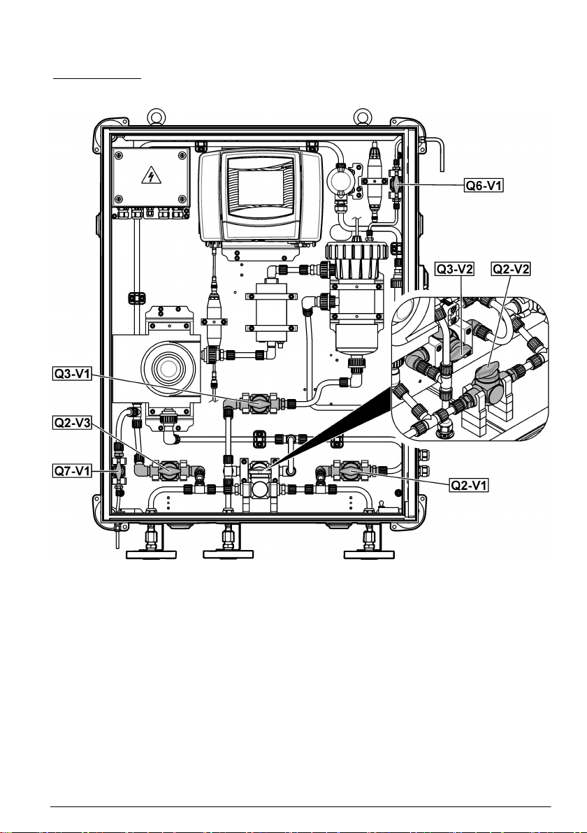
Hach Debubb User manual

DOC273.97.90748
Debubbler
05/2021, Edition 1
User Instructions
Bedienungsanleitung
Istruzioni per l'uso
取扱説明書
사용 설명서
Brugervejledninger
Gebruiksaanwijzingen
Οδηγίες χρήσης

Table of Contents
English..............................................................................................................................3
Deutsch.......................................................................................................................... 10
Italiano............................................................................................................................ 17
日本語............................................................................................................................. 24
한국어............................................................................................................................. 31
Dansk..............................................................................................................................38
Nederlands....................................................................................................................45
Ελληνικά........................................................................................................................ 52
2

Table of Contents
1 General information on page 3
2 Product components on page 4
3 Assembly on page 5
4 Installation on page 6
5 Adjust the PRVs on page 8
Section 1 General information
In no event will the manufacturer be liable for direct, indirect, special, incidental or consequential
damages resulting from any defect or omission in this manual. The manufacturer reserves the right to
make changes in this manual and the products it describes at any time, without notice or obligation.
Revised editions are found on the manufacturer’s website.
1.1 Safety information
The manufacturer is not responsible for any damages due to misapplication or misuse of this product
including, without limitation, direct, incidental and consequential damages, and disclaims such
damages to the full extent permitted under applicable law. The user is soley responsible to identify
critical application risks and install appropriate mechanisms to protect processes during a possible
equipment malfunction.
Please read this entire manual before unpacking, setting up or operating this equipment. Pay
attention to all danger and caution statements. Failure to do so could result in serious injury to the
operator or damage to the equipment.
Make sure that the protection provided by this equipment is not impaired. Do not use or install this
equipment in any manner other than that specified in this manual.
1.2 Icons used in illustrations
Manufacturer supplied parts User supplied parts Do one of these options Use fingers only
English 3

Section 2 Product components
Make sure that all components have been received. Refer to Figure 1. If any items are missing or
damaged, contact the manufacturer or a sales representative immediately.
Figure 1 Product components
1 Debubbler parts 8 M12 metal split washers, DIN127 (4x)
2 Pressure reducing valves (PRVs) 9 M12 metal nuts, DIN934 (4x)
3 Tubing, ½-inch OD x 3/8-inch ID 10 Plumbing fitting (6x)
4 Counter flanges, DN25 (2x) 11 Sealing rings (6x)
5 Flange gasket 12 Cutting rings (6x)
6 M12 x 80 metal bolts, DIN267 (4x) 13 Nuts (6x)
7 M12 metal washers, DIN125 (4x)
4 English

Section 4 Installation
1. Install three counter flanges on the ScrubberMonitor. Refer to Figure 3.
2. Plumb the debubbler to the ScrubberMonitor. Refer to Figure 4.
Figure 3 Flange installation—ScrubberMonitor
1 M12 x 80 metal bolts, DIN267 (12x) 5 Thread lubricant for bolts (anti-seize)
2 M12 metal washers, DIN125 (12x) 6 Counter flanges, DN25 (3x)
3 M12 metal split washers, DIN127 (12x) 7 Flange gaskets (3x)
4 M12 metal nuts, DIN934 (12x)
6 English

Figure 4 Plumb the debubbler
1 External sample line (not included) 4 Sample inlet
2 Sample outlet 5 External drain line (not included)
3 Drain 6 Open drain
English 7

Section 5 Adjust the PRVs
Adjust the two orange pressure reducing valves (PRV) of the debubbler.
Items to collect:
• Flat-head screwdriver, small
• Allen wrench, 8 mm
• Open-end wrench, 24 mm
1. Close the two shutoff valves of the debubbler.
2. Close the seven valves in the ScrubberMonitor. Refer to Figure 5.
3. Open bypass valve (Q2-V2).
4. Start the flow of sample water to the debubbler. Water flows from the debubbler drain.
5. Adjust the orange pressure reducing valve (PRV) that is near the floor so that water flows out the
debubbler drain when the bottom shutoff valve is closed, but not when the bottom shutoff valve is
open as follows:
a. Use the flat-head screwdriver to remove the black cap from the PRV.
b. Use the open-end wrench to loosen the locking nut.
c. Use the Allen wrench to turn the set screw clockwise until the pressure gauge on the PRV
shows 3 bar. The flow of water from the debubbler drain stops.
d. Turn the set screw counter-clockwise until the flow of water from the debubbler drain starts
again.
e. Open the shutoff valve at the bottom of the debubbler. Make sure that the flow of water from
the debubbler drain stops. If not, adjust the set screw again.
f. Tighten the locking nut.
g. Install the black cap on the PRV.
6. Flush the external sample line as follows:
a. Open the bypass valve (Q2-V2).
b. Let the sample water flow through the bypass tubing until the water flow removes the
construction materials in the sample line.
c. Close the bypass valve (Q2-V2).
7. Open the sample inlet and outlet valves (Q2-V1 and Q2-V3). Refer to Figure 5. Water flows into
the instrument.
8. When there is no longer air in the instrument tubing, remove the air from the sample flow cell as
follows:
a. Put a container under the vent. The vent is on the right side at the top of the ScrubberMonitor.
b. Open the vent valve (Q6-V1). Refer to Figure 5.
c. When water comes out of the vent, close the vent valve (Q6-V1).
9. Adjust the orange PRV that is above the instrument so that water does not flow from the top of
the debubbler when the top shutoff valve is open as follows:
a. Make sure that the shutoff valve at the top of the debubbler is closed.
b. Use the flat-head screwdriver to remove the black cap from the PRV.
c. Use the open-end wrench to loosen the locking nut.
d. Use the Allen wrench to turn the set screw fully clockwise (closed) so water cannot get past
the PRV.
e. Open the top shutoff valve of the debubbler.
f. Turn the set screw counter-clockwise until the sound of a gas leak is heard, but no water gets
past the PRV.
g. Tighten the locking nut.
h. Install the black cap on the PRV.
8 English

10. Examine the instrument for leaks. Tighten the fittings to stop leaks as necessary.
11. Adjust the bypass valve (Q2-V2) (or the external shutoff valve) until the sample flow meter shows
approximately 120 L/h.
Figure 5 Valves
English 9

Inhaltsverzeichnis
1 Allgemeine Informationen auf Seite 10
2 Produktkomponenten auf Seite 11
3 Montage auf Seite 12
4 Installation auf Seite 13
5 Einstellen der Druckminderungsventile
auf Seite 15
Kapitel 1 Allgemeine Informationen
Der Hersteller ist nicht verantwortlich für direkte, indirekte, versehentliche oder Folgeschäden, die
aus Fehlern oder Unterlassungen in diesem Handbuch entstanden. Der Hersteller behält sich
jederzeit und ohne vorherige Ankündigung oder Verpflichtung das Recht auf Verbesserungen an
diesem Handbuch und den hierin beschriebenen Produkten vor. Überarbeitete Ausgaben der
Bedienungsanleitung sind auf der Hersteller-Webseite erhältlich.
1.1 Sicherheitshinweise
Der Hersteller ist nicht für Schäden verantwortlich, die durch Fehlanwendung oder Missbrauch
dieses Produkts entstehen, einschließlich, aber ohne Beschränkung auf direkte, zufällige oder
Folgeschäden, und lehnt jegliche Haftung im gesetzlich zulässigen Umfang ab. Der Benutzer ist
selbst dafür verantwortlich, schwerwiegende Anwendungsrisiken zu erkennen und erforderliche
Maßnahmen durchzuführen, um die Prozesse im Fall von möglichen Gerätefehlern zu schützen.
Bitte lesen Sie dieses Handbuch komplett durch, bevor Sie dieses Gerät auspacken, aufstellen oder
bedienen. Beachten Sie alle Gefahren- und Warnhinweise. Nichtbeachtung kann zu schweren
Verletzungen des Bedienpersonals oder Schäden am Gerät führen.
Stellen Sie sicher, dass die durch dieses Messgerät gebotene Sicherheit nicht beeinträchtigt wird.
Verwenden bzw. installieren Sie das Messgerät nur wie in diesem Handbuch beschrieben.
1.2 In Abbildungen benutzte Zeichen
Vom Hersteller
bereitgestellte Teile
Vom Benutzer
bereitgestellte Teile
Führen Sie eine
dieser Optionen aus
Nur Finger
verwenden
10 Deutsch

Kapitel 2 Produktkomponenten
Stellen Sie sicher, dass Sie alle Teile erhalten haben. Siehe Abbildung 1. Wenn Komponenten fehlen
oder beschädigt sind, kontaktieren Sie bitte umgehend den Hersteller oder Verkäufer.
Abbildung 1 Produktkomponenten
1 Teile des Entlüfters 8 M12 Metallfederringe, DIN127 (4x)
2 Druckminderungsventile 9 M12 Metallmuttern, DIN934 (4x)
3 Schlauch, ½ Zoll AD x 3/8 Zoll ID 10 Rohranschlüsse (6x)
4 Gegenflansche, DN25 (2x) 11 Dichtungsringe (6x)
5 Flanschdichtung 12 Schneidringe (6x)
6 M12 x 80 Metallbolzen, DIN267 (4x) 13 Muttern (6x)
7 M12 Metallunterlegscheiben, DIN125 (4x)
Deutsch 11

Kapitel 4 Installation
1. Montieren Sie drei Gegenflansche am ScrubberMonitor. Siehe Abbildung 3.
2. Schließen Sie den Entlüfter an den ScrubberMonitor an. Siehe Abbildung 4.
Abbildung 3 Flansch-Montage – ScrubberMonitor
1 M12 x 80 Metallbolzen, DIN267 (12x) 5 Gewindeschmiermittel für Bolzen (Anti-
Seize)
2 M12 Metallunterlegscheiben, DIN125 (12x) 6 Gegenflansche, DN25 (3x)
3 M12 Metallfederringe, DIN127 (12x) 7 Flanschdichtungen (3x)
4 M12 Metallmuttern, DIN934 (12x)
Deutsch 13

Abbildung 4 Anschließen des Entlüfters
1 Externe Probenleitung (nicht im Lieferumfang
enthalten)
4 Probenzulauf
2 Probenauslass 5 Externe Abflussleitung (nicht im
Lieferumfang enthalten)
3 Abfluss 6 Ablass öffnen
14 Deutsch

Kapitel 5 Einstellen der Druckminderungsventile
Stellen Sie die beiden orangefarbenen Druckminderungsventile (pressure reducing valves, PRV) des
Entlüfters ein.
Erforderliche Artikel:
• Schlitzschraubendreher, klein
• Innensechskantschlüssel, 8 mm
• Gabelschlüssel, 24 mm
1. Schließen Sie die beiden Absperrventile des Entlüfters.
2. Schließen Sie die sieben Ventile im ScrubberMonitor. Siehe Abbildung 5.
3. Öffnen Sie das Bypass-Ventil (Q2-V2).
4. Starten Sie den Zufluss von Probenwasser zum Entlüfter. Wasser fließt aus dem Ablauf des
Entlüfters.
5. Stellen Sie das sich in Bodennähe befindende orangefarbene Druckminderungsventil so ein,
dass Wasser aus dem Ablauf des Entlüfters fließt, wenn das untere Absperrventil geschlossen
ist, jedoch nicht, wenn das untere Absperrventil geöffnet ist:
a. Verwenden Sie den Schlitzschraubendreher, um die schwarze Kappe vom
Druckminderungsventil zu entfernen.
b. Lösen Sie die Sicherungsmutter mit dem Gabelschlüssel.
c. Drehen Sie die Einstellschraube mit dem Innensechskantschlüssel im Uhrzeigersinn, bis das
Manometer am Druckminderungsventil 3 bar anzeigt. Der Wasserdurchfluss aus dem Ablauf
des Entlüfters wird unterbrochen.
d. Drehen Sie die Stellschraube gegen den Uhrzeigersinn, bis der Wasserdurchfluss aus dem
Ablauf des Entlüfters wieder einsetzt.
e. Öffnen Sie das Absperrventil am Boden des Entlüfters. Stellen Sie sicher, dass der
Wasserdurchfluss aus dem Ablauf des Entlüfters stoppt. Ist dies nicht der Fall, stellen Sie die
Stellschraube erneut ein.
f. Ziehen Sie die Befestigungsmutter an.
g. Montieren Sie die schwarze Kappe auf dem Druckminderungsventil.
6. Spülen Sie die externe Probenleitung wie folgt:
a. Öffnen Sie das Bypassventil (Q2-V2).
b. Lassen Sie das Probenwasser durch den Bypass-Schlauch fließen, bis der Wasserdurchfluss
die Baustoffe in der Probenleitung entfernt.
c. Schließen Sie das Bypassventil (Q2-V2).
7. Öffnen Sie die Probenzulauf- und -auslassventile (Q2-V1 und Q2-V3). Siehe Abbildung 5.
Wasser fließt in das Gerät.
8. Wenn sich keine Luft mehr im Geräteschlauch befindet, entfernen Sie die Luft aus der
Probendurchflusszelle folgendermaßen:
a. Stellen Sie einen Behälter unter die Entlüftung. Die Entlüftung befindet sich auf der rechten
Seite oben am ScrubberMonitor.
b. Öffnen Sie das Entlüftungsventil (Q6-V1). Siehe Abbildung 5.
c. Wenn Wasser aus der Entlüftung austritt, schließen Sie das Entlüftungsventil (Q6-V1).
9. Stellen Sie das orangefarbene Druckminderungsventil über dem Gerät so ein, dass kein Wasser
von der Oberseite des Entlüfters fließt, wenn das obere Absperrventil geöffnet ist:
a. Stellen Sie sicher, dass das Absperrventil an der Oberseite des Entlüfters geschlossen ist.
b. Verwenden Sie den Schlitzschraubendreher, um die schwarze Kappe vom
Druckminderungsventil zu entfernen.
c. Lösen Sie die Sicherungsmutter mit dem Gabelschlüssel.
d. Drehen Sie die Stellschraube mit dem Innensechskantschlüssel vollständig im Uhrzeigersinn
(geschlossen), damit kein Wasser aus dem Druckminderungsventil austreten kann.
Deutsch 15

e. Öffnen Sie das obere Absperrventil des Entlüfters.
f. Drehen Sie die Stellschraube gegen den Uhrzeigersinn, bis das Geräusch eines Gaslecks zu
hören ist, aber kein Wasser aus dem Druckminderungsventil austritt.
g. Ziehen Sie die Befestigungsmutter an.
h. Montieren Sie die schwarze Kappe auf dem Druckminderungsventil.
10. Untersuchen Sie das Gerät auf Lecks. Ziehen Sie die Anschlüsse nach Bedarf an, um Lecks zu
verhindern.
11. Stellen Sie das Bypass-Ventil (Q2-V2) (oder das externe Absperrventil) so ein, dass der
Probendurchflussmesser ca. 120 L/h anzeigt.
Abbildung 5 Ventile
16 Deutsch

Sommario
1 Informazioni generali a pagina 17
2 Componenti del prodotto a pagina 18
3 Assemblaggio a pagina 19
4 Installazione a pagina 20
5 Regolazione delle valvole PRV a pagina 22
Sezione 1 Informazioni generali
In nessun caso, il produttore potrà essere ritenuto responsabile per danni diretti, indiretti o accidentali
per qualsiasi difetto o omissione relativa al presente manuale. Il produttore si riserva il diritto di
apportare eventuali modifiche al presente manuale e ai prodotti ivi descritti in qualsiasi momento
senza alcuna notifica o obbligo preventivi. Le edizioni riviste sono presenti nel sito Web del
produttore.
1.1 Informazioni sulla sicurezza
Il produttore non sarà da ritenersi responsabile in caso di danni causati dall'applicazione errata o
dall'uso errato di questo prodotto inclusi, a puro titolo esemplificativo e non limitativo, i danni diretti,
incidentali e consequenziali; inoltre declina qualsiasi responsabilità per tali danni entro i limiti previsti
dalle leggi vigenti. La responsabilità relativa all'identificazione dei rischi critici dell'applicazione e
all'installazione di meccanismi appropriati per proteggere le attività in caso di eventuale
malfunzionamento dell'apparecchiatura compete unicamente all'utilizzatore.
Prima di disimballare, installare o utilizzare l’apparecchio, si prega di leggere l’intero manuale. Si
raccomanda di leggere con attenzione e rispettare le istruzioni riguardanti note di pericolosità. La non
osservanza di tali indicazioni potrebbe comportare lesioni gravi all'operatore o danni all'apparecchio.
Assicurarsi che i dispositivi di sicurezza insiti nell'apparecchio siano efficaci all'atto della messa in
servizio e durante l'utilizzo dello stesso. Non utilizzare o installare questa apparecchiatura in modo
diverso da quanto specificato nel presente manuale.
1.2 Icone usate nelle illustrazioni
Parti fornite dal produttore Parti fornite dall'utente Eseguire una di queste
opzioni
Utilizzare solo le dita
Italiano 17

Sezione 2 Componenti del prodotto
Accertarsi che tutte le parti oggetto della fornitura siano state ricevute. Fare riferimento alla sezione
Figura 1. In caso di componenti mancanti o danneggiati, contattare immediatamente il produttore o il
rappresentante.
Figura 1 Componenti del prodotto
1 Componenti del debollatore 8 Rondelle spaccate in metallo M12,
DIN127 (4x)
2 Valvole limitatrici della pressione (PRV) 9 Dadi in metallo M12, DIN934 (4x)
3 Tubo, ½" D.E. x 3/8" D.I. 10 Raccordo tubo (6x)
4 Controflange, DN25 (2x) 11 Anelli di tenuta (6x)
5 Guarnizione flangia 12 Anelli taglienti (6x)
6 Bulloni in metallo M12 x 80, DIN267 (4x) 13 Dadi (6x)
7 Rondelle in metallo M12, DIN125 (4x)
18 Italiano

Sezione 4 Installazione
1. Montare tre controflange sullo ScrubberMonitor. Fare riferimento a Figura 3.
2. Collegare il debollatore allo ScrubberMonitor. Fare riferimento a Figura 4.
Figura 3 Installazione della flangia - ScrubberMonitor
1 Bulloni in metallo M12 x 80, DIN267 (12x) 5 Lubrificante per filettature per bulloni
(antigrippaggio)
2 Rondelle in metallo M12, DIN125 (12x) 6 Controflange, DN25 (3x)
3 Rondelle spaccate in metallo M12,
DIN127 (12x)
7 Guarnizioni flangia (3x)
4 Dadi in metallo M12, DIN934 (12x)
20 Italiano
Table of contents
Languages:
Other Hach Laboratory Equipment manuals

Hach
Hach PHC745 User manual

Hach
Hach MET ONE 3400 Series User manual

Hach
Hach BODTrak II User manual

Hach
Hach QP 1680-TOC/TNb Quick manual

Hach
Hach ISENH4181 User manual

Hach
Hach POCKET TURBIDIMETER User manual

Hach
Hach ORBISPHERE 29122 User manual

Hach
Hach DR 3900 Quick manual

Hach
Hach DRB 200 User manual

Hach
Hach ORBISPHERE K1200 Quick manual

Hach
Hach sensION+ MM374 User manual

Hach
Hach TitraLab AT1000 Series Quick manual

Hach
Hach QbD1200 AutoSampler User manual

Hach
Hach SIP 10 User manual

Hach
Hach TitraLab User manual

Hach
Hach BODTrak II Quick manual

Hach
Hach HQ440d Quick manual

Hach
Hach HQ440d User manual

Hach
Hach TitraLab Quick manual

Hach
Hach LT 200 User manual