manuals.online logo
Brands
  1. Home
  2. •
  3. Brands
  4. •
  5. hager
  6. •
  7. Control Unit
  8. •
  9. hager TRM600AU User manual

hager TRM600AU User manual

Radio control for latching relay,
timer
cfg fct
L/N
TRM600
ε 0,5A AC1 230 V 50Hz
433.5 Mhz 10mW
3,5
max
cfg fct
L/N
TRM600AU
ε 0,5A AC1 230 V
50Hz
433.5 Mhz 10mW
TRM600AU
0,5A AC1 230 V
50Hz
433.5 Mhz 10mW
L/N
z
Technical characteristics
Supply voltage 230 V +10 %-15% 50 Hz
240 V +6%/-6% 50 Hz
Product consumption 100mW (max. 150mW)
Transmission frequency/
Emission power
433,05 - 434,79 MHz
10 mW
Dimensions 40 x 40 x 18 mm
Max. switch current 0.5A
Contact closure
duration 200ms
Degree of protection IP 20
Operating altitude ≤ 2000 m
Pollution degree 2
Overvoltage category III
Operating temperature -15 °C —> + 45 °C
Storage temperature - 25°C —> + 70 °C
Receiver category 2 / Transmitter duty cycle
<10%
Electric connection: 0,5 mm
2
—> 1,5 mm
2
0,5 mm
2
—> 2,5 mm
2
6LE005074D
- The device is to be installed only by a
qualified electrician in accordance with
the installation standards in force in the
country.
- Cut o the 230V power supply before
connecting the device.
The TRM600AU allows to add a radio control to an
existing latching relay or timer circuit powered by
230V. It is a radio receiver which only delivers a
calibrated pulse. It is dedicated to this application
and is placed in a flush mounted box, behind one of
the push buttons of the circuit to control. It connects
in parallel to the push button and consumes equal
to that required by a neon indicator of a push
button.
The TRM600AU is itself controlled through radio
transmitters. On each command received, its
output contact closes for 200 ms to control the
latching relay or timer in question.
Legend
1Push button and function LED Tof the output
2Push button and configuration LED R
3Terminal block
Functions
•
Single function receiver (pulse) controlled by radio
• 1 pulse output to control a latching relay or timer
In operation :
• Option of manual control of the output: each
press of the T
push button = 1 control pulse.
• Display of the output status on the fct LED: 1
single red flash corresponds to 1 pulse of 200 ms.
Quicklink configuration
Quicklink is the name of the tool free Hager
configuration mode for radio products. It uses the
function (fct) and configuration (cfg) buttons and
its Leds, located directly on the products. Only
the “pulse” function (select the timer symbol) and
erasing of the link are available on this product.
Limitations
Only latching relays or timers controlled at 230V
are compatible. In case of use with illuminated
push buttons, the current consumed by the product
must be considered as < than 1mA.
Factory Reset
Press and hold the Rpush button until the cfg
LED starts flashing (>10s). The factory reset is
complete when the cfg LED light goes out.
This operation leads to complete erasing of the
product configuration, regardless of the configuration
mode. After switching on or a factory reset, wait for
15 sec. before proceeding with configuration.
OThis manual is an integral part of the product
and must be kept by the end user.
6LE005074D1
TRM600AU
Complies with
IMDA Standards
DA101847
Metal surfaces in the direct vicinity of the
product (e.g. flush mounted metal boxes)
may reduce the radio range.
Avoid the use of a metal front plate for
switches in combination with flush mounted
metal boxes.
Hager Controls hereby declares that the radio
transmitter/receiver complies with the 2014/53/
EU directive.
The CE declaration can be consulted
on the site:
www.hager.com
åand
In1 In2
cfg
TRM702AU
IP30
Configuring a pulse function (5 steps)
Example : Link between a conventional push button connected to the radio transmitter TRM702AU and the TRM600AU receiver for pulse function.
Action Result
Starting configuration
Give a short press on the Jbutton of
the transmitter or transmitter/receiver. The cfg •LEDs of all the
receivers and the emitter
come on.
Input selection
Give a short press on the button to be
configured. The cfg •LED of the emitter
flashes for 1 s.
Function selection
Select the function by successive short
presses on the Kbutton of the receiver
to be controlled.
Scrolling of the functions
indicated by the colour of the
fct LED :
- first press = pulse function
- second press = delete link
Confirmation of the function
Press for > 2s on button Kof the
receiver until the cfg •LED flashes.
The function identified by
the colour of the fct LED
is confirmed.
Exiting configuration mode
Give a short press on the J
button of the transmitter or transmitter/
receiver.
The cfg •LEDs of all the
receivers and the emitter
go out. End of configuration.
Display of a configured function
In step 2the fct LED indicates the colour of the
configured function.
Group control
Repeat steps 3and 4on the other receivers to
be integrated in a group.Only the function selected
on the first receiver and clearing will be available
for selection on the other receivers.
Editing a configured function
In step 3,you can edit the displayed function,
except in the case of group control where it is
necessary to clear the receivers of the group
before choosing a new function.
Clearing a configured function
In step 3select the "Clear" function and then
confirm in step 4.
Error signals
A very rapidly flashing cfg •LED indicates an error
or an incompatible link. (e.g. a group control mixing
lighting and shutter commands).
System limit
A product may be linked to a maximum to 20 other
products.
In1 In2
In1 In2
cfg
cfg
TRM702AU
IP30
TRM702AU
IP30
In1 In2
In1 In2
cfg
cfg
TRM702AU
IP30
TRM702AU
IP30
In1 In2
cfg
TRM702AU
IP30
TRM600AU
0,5A AC1 230 V 50Hz
433.5 Mhz 10mW
L/N
In1 In2
TRM702AU
IP30
cfg
TRM600AU
0,5A AC1 230 V 50Hz
433.5 Mhzz 10mW
1x
2x
3x
4x…
L/N
fct
TRM600AU
0,5A AC1 230 V 50Hz
433.5 MhzW
> 2s
L/N
fct
TRM600AU
0,5A AC1 230 V 50Hz
433.5 Mhz 10mW
L/N
TRM600AU
0,5A AC1 230 V 50Hz
433.5 Mhz 10mW
L/N
In1 In2
cfg
TRM702AU
IP30
L
TRM
600AU
3 wires 4 wires TRM702AU
A1
A2
1
2
N
L
A1
A2
1
2
N
In1In2
TRM702A
RF1.M EC/EP
868 MHz
IP30
cfg
TRM
600AU
2x3x1x
= 200ms DeleteLed fct
TRM600AU
0,5A AC1 230 V 50Hz
433.5 Mhz 10mW
L/N
6LE005074D
2Hager Controls S.A.S., 33 rue Saint-Nicolas, B.P. 10140, 67703 SAVERNE CEDEX, France - www.hager.com

Other hager Control Unit manuals

hager TYF61 Series User manual

hager

hager TYF61 Series User manual

hager RTN100X User manual

hager

hager RTN100X User manual

hager TRB221A-5A User manual

hager

hager TRB221A-5A User manual

hager TK 301 User manual

hager

hager TK 301 User manual

hager RE 310 Series User manual

hager

hager RE 310 Series User manual

hager H3 x250 User manual

hager

hager H3 x250 User manual

hager TYB601A User manual

hager

hager TYB601A User manual

hager RTN710X User manual

hager

hager RTN710X User manual

hager RCBO-AFDD User manual

hager

hager RCBO-AFDD User manual

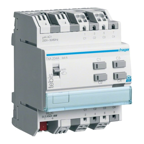
hager tebis TXA204A User manual

hager

hager tebis TXA204A User manual

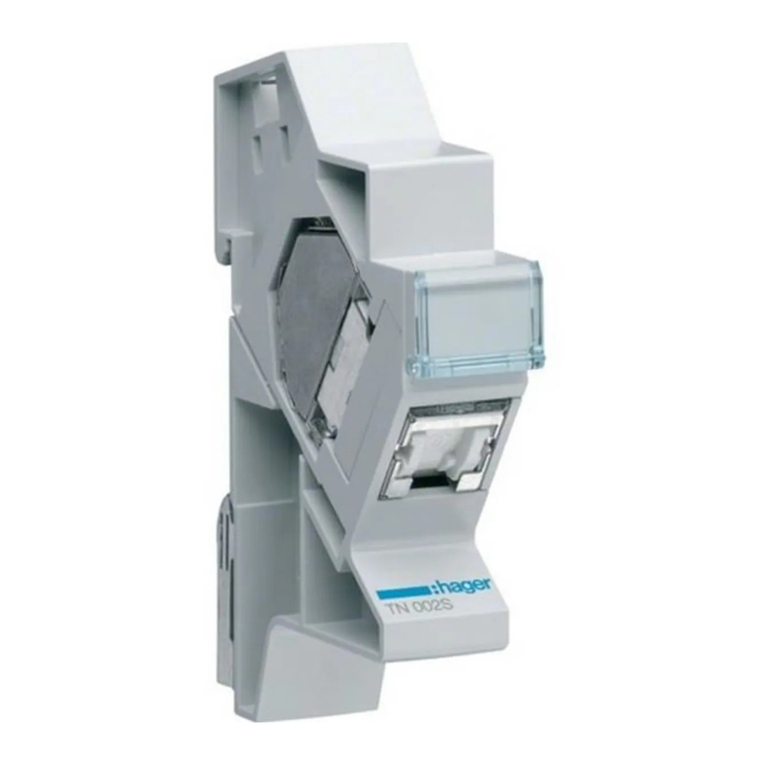
hager TN002S User manual

hager

hager TN002S User manual

hager ZZ45WAN2PP User manual

hager

hager ZZ45WAN2PP User manual

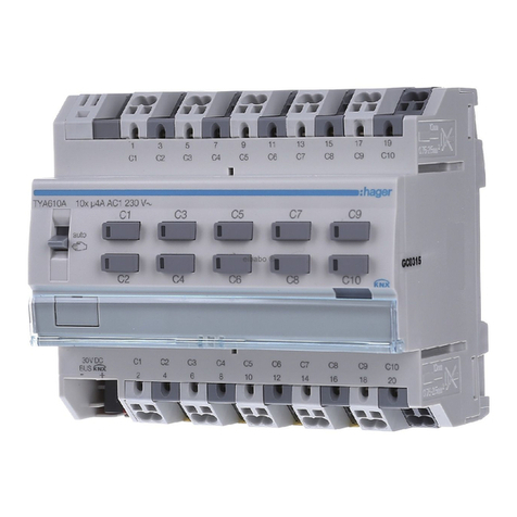
hager TYA610A User manual

hager

hager TYA610A User manual

hager Klik LCM User manual

hager

hager Klik LCM User manual

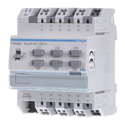
hager TYA606 Series User manual

hager

hager TYA606 Series User manual

hager WK305 User manual

hager

hager WK305 User manual

hager Vega D FD Series User manual

hager

hager Vega D FD Series User manual

hager h3 h400 User manual

hager

hager h3 h400 User manual

hager TXA101 User manual

hager

hager TXA101 User manual

hager tebis TX100 User manual

hager

hager tebis TX100 User manual

hager RE 410 Series User manual

hager

hager RE 410 Series User manual

hager TYA606A User manual

hager

hager TYA606A User manual

hager TN002 User manual

hager

hager TN002 User manual

hager JK11254D Manual

hager

hager JK11254D Manual

Popular Control Unit manuals by other brands

ZURN QHCMKIT5 installation instructions

ZURN

ZURN QHCMKIT5 installation instructions

ProFlo PF4001PTD installation instructions

ProFlo

ProFlo PF4001PTD installation instructions

Festo VZQA-C-M22C Series Repair instructions

Festo

Festo VZQA-C-M22C Series Repair instructions

FAAC 844 T manual

FAAC

FAAC 844 T manual

National Instruments NI FlexRIO PXIe-7971R Getting started guide

National Instruments

National Instruments NI FlexRIO PXIe-7971R Getting started guide

Mesto Neles ValvGuard VG9000H operating instructions

Mesto

Mesto Neles ValvGuard VG9000H operating instructions

JS Automation MPC3024A user manual

JS Automation

JS Automation MPC3024A user manual

ICStation ZK-301B manual

ICStation

ICStation ZK-301B manual

Velleman K8006 Illustrated assembly manual

Velleman

Velleman K8006 Illustrated assembly manual

Midea SMK-D140HHN1-3 manual

Midea

Midea SMK-D140HHN1-3 manual

Knick Protos Compa 3400(X)-081 user manual

Knick

Knick Protos Compa 3400(X)-081 user manual

Dyna-Flo 570 Operation, Parts, and Instruction Manual

Dyna-Flo

Dyna-Flo 570 Operation, Parts, and Instruction Manual

Pickering PXI BRIC 40-595A user manual

Pickering

Pickering PXI BRIC 40-595A user manual

Edwards PV16EKA instruction manual

Edwards

Edwards PV16EKA instruction manual

Vector OPA2-MOD manual

Vector

Vector OPA2-MOD manual

NPM AD1231 user manual

NPM

NPM AD1231 user manual

Emerson ES-805 Series instruction manual

Emerson

Emerson ES-805 Series instruction manual

Quectel NB-IoT Module Series Hardware design

Quectel

Quectel NB-IoT Module Series Hardware design

manuals.online logo
manuals.online logoBrands
  • About & Mission
  • Contact us
  • Privacy Policy
  • Terms and Conditions

Copyright 2025 Manuals.Online. All Rights Reserved.