manuals.online logo
Brands
  1. Home
  2. •
  3. Brands
  4. •
  5. hager
  6. •
  7. Control Unit
  8. •
  9. hager tebis TX100 User manual

hager tebis TX100 User manual

How to... / What to do if...
Configuration tool tebis
TX 100
6T 7231a
Touches écran
La fonction de chaque tou-
che est indiquée sur l’écran
au dessus d’elle. La fonc-
tion varie selon l’écran
- Valide l’opération en cours
- Sélectionne un enu
- Valide la saisie
-
Change la fonction des
touches de gauche
(sélection soit d’un
nu éro d’entrée soit
d’une fonction)
- Retour au enu précédent
- Active la sortie sélectionnée
- Lance la nu érotation des
sorties de l'installation
Accès aux écrans d’aide à
l’installation
Accès aux enus
1
Niveau de charge batterie
Sortie
Entrée
Produit radio
Produit filaire
Préparation d’un lien
Lien établi
Suppression d’un lien
Acquittement sonore
• Un “bip” si ple indique une
opération réussie
• Un double “bip” indique une
opération qui a échouée
Sommaire g n ral
Description des touches
Description de l’affichage
Informations relatives
aux entr es
Informations relatives
aux sorties
1
1
Afficheur
Touche
arche / arrêt
Touche
“Accès au enu”
( ê e fonction
que )
Sortie
- Sélectionne un
nu éro de sortie
- Déplace ent dans
les enus
N° entrée
Fonction de l’entrée
Type de la sortie
N° sortie
No bre de sorties liées
à l’entrée affichée (ex: 5
sorties pour l’entrée 17)
No bre de
sorties de
l’installation
No bre
d’entrées de
l’installation
Défaut sur
la sortie
affichée
Défaut sur
l’entrée
affichée
No bre total de
défauts de l’installation
Entr e
- Sélectionne un
nu éro d’entrée
- Sélectionne une
fonction affectée
à l’entrée
sélectionnée
- Déplace ent
dans les enus
How to... . . . . . . . . . . . . . . . . . . . . . . . . . . . . . . . . . . . . . . . . . . . . .2
1. Dialing and product research phase . . . . . . . . . . . . . . . . . . . . . . . .2
2. Configuration or progra ing phase . . . . . . . . . . . . . . . . . . . . . . .3
3. Others . . . . . . . . . . . . . . . . . . . . . . . . . . . . . . . . . . . . . . . . . . . . . . . . . .13
What to do if... . . . . . . . . . . . . . . . . . . . . . . . . . . . . . . . . . . . . . .16
4. Dialing and product research phase . . . . . . . . . . . . . . . . . . . . . . .16
5. Configuration or progra ing phase . . . . . . . . . . . . . . . . . . . . . .19
6. Others . . . . . . . . . . . . . . . . . . . . . . . . . . . . . . . . . . . . . . . . . . . . . . . . . .24
Annexes... . . . . . . . . . . . . . . . . . . . . . . . . . . . . . . . . . . . . . . . . . .25
Clavier
alphanu érique
No bre d’entrées pilotant
la sortie sélectionnée
(ex: la sortie 25 est pilotée
par 2 entrées dont la 17)
Barre de titre
t
o
u
t
e
la
p
a
g
e
à
t
r
a
d
u
i
r
e
3
Dialing and product research phase
Num. How to...
3To dial outputs just
added to an exis-
ting installation…
Solutions
1
Phase configuration ou programmation
Num. Que faire pour...
4To progra the
extension of an
Easy installation
via ETS.
Solutions
2
2
Dialing and product research phase
1
Num. How to...
1To order the auto-
atic dialing of
outputs.
Solutions
2To dial the inputs.
- Make sure that no output product (wire and radio) is under voltage.
- Set the configurer in ode 'prog'.
- Make a long pressure of key to start the auto atic search of outputs.
- Connect the first product.
- Wait until the nu ber of outputs is incre ented on the screen of TX100 (e.g. 6
outputs for TX206A).
- Connect the following product and wait again until the nu ber of outputs is
incre ented on the screen of TX100.
- Use the sa e procedure for co pleting the installation.
Set TX100 in ode Nu '.
Modular wire inputs: Press pushbuttons on TX314 and TX316 product front face or
pushbuttons connected to the inputs.
Modules to be e bedded in unidir: press the pushbutton associated with the desired
input and follow the instructions of TX100.
Re ote controls: press the key to dial and follow instructions of TX100.
Radio odule bidir: press the pushbutton connected to the desired input.
Wire products to be e bedded: press the pushbutton connected to the desired input
Presence detector: Set the product in test ode (potentio eter in position
''Test'').
Clock: Press key (A or B) corresponding to the desired channel.
Di er switch: Press the pushbutton of product front faceRoo controler: Press the
sensitive keys to be dialed.
- Set the configurer in ode 'prog'.
- Give the key a long press to start the auto atic search of outputs.
- The configurer seeks and dials auto atically all new outputs present in the
installation.
- Refer to §4 page 12 of TX100 User's Instructions.
- First of all, check if "ETS Mode" is activated: See § 11 on page 28 of TX100
instructions.
Note: this ode is active by default,
- If the ETS ode is deactivated perfor installation factory return (including unidir
products), activate "ETS ode" and delete S art Media Card; then reconfigure the
installation.
5
Configuration or programming phase
Num. How to...
6To configure a pre-
set scenario for a
shutter or a blind.
Solutions
2
4
Configuration or programming phase
Num. How to...
5To configure and
set a scenario.
Solutions
2
- For a scenario including rolling shutters or blinds, first set up the lowering ti e (see
ite No. 10).
- Dial the input intended to activate the scenario to be configured.
- Select the scenario function S1 to S8.
Note: Caution: for drivers of shutters and blinds, S1 and S5 scena-
rios can be odified. Scenario 1 is freelyconfigurable (see
ite s No. 7 & 8); for scenarios S2 to S5, 4 positions are
available (see ite s 7 and 8)S6 to S8 scenarios are preset
(see ite 6)Caution: for di ers TX211 and TX214, scena-
rios S1, S2 and S3 can be odified. S2 to S8 scenarios are
preset. See product note.
- Establish a link between this input (push-button) and all outputs concerned.
Note: The creation of link is described in the TX100 Users’
Instructions.
- Return to "auto" ode.
- Activate the scenario by giving the corresponding scenario input a short press.
- Set outputs in the desired state (switch-on, switch-off, di ing, position of shutter
(see ite s 7and 8). This can be done with local controls of each output or with
anual controls on output odules.
- Store the scenario by giving scenario activation pushbutton a long press (5s)
(for ti e switch and di er switch, see ite 9).
- Set up the total lowering ti e of rolling shutter or blind (see note No.10).
- Dial the input associated with the scenario to be configured.
- Choose the function preset scenario (S6 with S8 foroutputs blinds/shutters):
Note: The positions of shutters or blinds for scenarios are defined as
follows:
- scenario 1: configurable
- scenario 2: (high, 1/4, 1/2, and low)
- scenario 3: (high, 1/4, 1/2, and low)
- scenario 4: (high, 1/4, 1/2, and low)
- scenario 5: (high, 1/4, 1/2, and low)
- scenario 6: high
- scenario 7: low
- scenario 8: 3/4 closed.
- Carry out a re ote loading of the product (see §6 page 21 of User’s Instructions
TX100).
- Establish a link between this input (push-button) and all outputs concerned.
Note: The creation of link is described in User’s Instructions TX100.
6
Configuration or programming phase
Num. How to...
7Special case:
To configure and
set a odifiable
scenario for rolling
shutters.
Solutions
2
7
Configuration or programming phase
Num. How to...
8Special case:
To configure and
set a odifiable
scenario for blinds.
Solutions
2
The position of the blind is configurable for scenarios 1 to 5.
- Set up the total lowering ti e of the blind (see ite No.10).
- Dial the input intended to activate the scenario.- Choose the configurable scenario
function (S1 to S5)- Establish a link between this input (push-button) and all outputs
concerned.
Note: The creation of link is described in User’s Instructions TX100.
- Return to ode «auto».
- Activate the scenario by a short press of corresponding input scenario.
- Position the blinds in high position, if necessary.
- Lower the blinds in the position desired with the local control.
- Then incline the slats (by short presses) until the desired position is reached (only
for the S1 scenario); this inclination will be taken into account for all configurable
scenarios.
Note: Do not start any raising during this setting, if not do this proce-
dure again.
- Store the scenario by a long press (5s) of pushbutton to activate the scenario (for
ti e switch and di er switch to see ite No.9).
Note: The position restored following activation of scenarios S2 to S5
corresponds to the position nearest to one of4 positions avai-
lable (high, 1/4, 1/2, and low) and the inclination of the slats
corresponds to that configured for scenario S1 (0 inclination by
default).
The position of the shutter is configurable for scenarios 1 to 5.
- Set up the total lowering ti e of the rolling shutter (see ite No.10).
- Dial the input intended to activate the scenario.
- Choose the configurable scenario function (S1 to S5).
- Establish a link between this input (push-button) and all outputs concerned.
Note: The creation of link is described in User’s Instructions TX100.
- Return to ode “auto”.
- Activate the scenario by giving the corresponding scenario input a short press
- Position the rolling shutters in high position, if necessary.
- Lower the shutters in the position desired with the local control.
Note: Do not perfor any raising during this setting, if not redo this
procedure.
- Store the scenario by giving a long press (5s) to the activation pushbutton of sce-
nario (for ti e switch and di er switch to see ite No.9).
Note: The position restored following activation of scenarios S2 to S5
corresponds to the position nearest to one of the 4 available
positions (high, 1/4, 1/2, and low).
9
Configuration or programming phase
Num. How to...
11 To link a ain
switch clock to
one or ore
switch slave
clocks.
Solutions
2
8
Configuration or programming phase
Num. How to...
9To store states of a
scenario controlled
by a ti e switch or
a di er switch.
Solutions
10 To set up the ti e
to lower a rolling
shutter or a blind.
2
Since push-buttons on front face of these products do not si ulate a long press, it is
necessary to use the input si ulation ode of TX100 (see §17 page 27 of User’s
Instructions TX100) to store the training.
Note: Press given the push-button ust last at least 5 seconds.
- Take a easure ent of total shutter lowering ti e.
- Press the key of TX100 to access enu.
- Select ''Product Manage ent”.
- Select ‘‘ Product Infor ation”.
- Select the product concerned.
Note: if the installation includes several drivers, the LEDs signalling
the state ofproduct channels selected fro the drop-down list
switch on. Pressing push-button on odular product front face
akes it also possible to identify it in the drop-down list. For
flush- ounted products, press the key push-button on odular
product front face akes it also possible to identify it in the
drop-down list. For flush- ounted products, press the key
of TX100 to activate the channeldesired.
- Press right-hand side screen key ‘‘PARAM’‘.
- Choose the channel concerned.
- Select the total lowering ti e fro drop-down enu based on the easure ent
taken previously.
- Perfor a forced re ote loading of the product (see §6 page 21 of User’s
Instructions TX100).
- Set the configurer in ode ' prog' and select the filter "+ Info" (see note of §3.2
page 11 of TX100 User’s Instructions).
Note: The special functions are at end of list: their nu bers start fro
512 and are decre ented.
- Link each input to each output .
For instance: for 3 ti e switches, 9 links are necessary.
- Select the Master fro ti e switches by pressing si ultaneously keys + or - until
the essage '' Slave OFF'' appears on the screen of this ti e switch.
- Check the synchronization of slave ti es switches of the aster ti e switch.
- Return to ode ' auto'.
11
Configuration or programming phase
Num. How to...
13 To link a wire input
state indication
to another
wire unput.
Solutions
2
10
Configuration or programming phase
Num. How to...
12 To link a ain di -
er switch to one
or ore di er
slave switches.
Solutions
2
- Identify the di er switch intended to operate as a Master and carry out a unit
factory return (see E17 page 18 of User’s Instructions TX100).
- Set the configurer in ode 'prog'.
- Guve the key a long press to start the auto atic search of outputs.
- Select the filter "+ Info" (see note §3.2 page 11 of User’s Instructions TX100).
Note: The special functions ( and ) are at the end of the
list: their nu bers start with 512 andare decre ented.
- Note the dialing of special channels of ain di er switch.
- Give the key again a long press by connecting the other di er switches, if
necessary.
- Carry out a link between the input of the ain di er switch and outputs
of all slave di er switches.
- Validate by a long press of key .
- Return to ode “auto”.
- Select the Expert ode (see §18 page 27 of User’s Instructions TX100).
- Set TX100 in ode '' Prog''.
- Select the desired indication input and the output to be linked.
- Enter the expert ode by pressing the centre screen key: the list of objects is
displayed e.g. link between an indication input of state ON/OFF of TX206C and
output of TX204A.
- Select object "ION/OFF" fro the list dedicated to inputs using the keys .
- Assign a group address to it or retain it if if a group address is already associated.
- Switch to the list of the functions dedicated to outputs by pressing the key .
- Select object "ON/OFF" of output fro the list dedicated to outputs using the keys
.
- Assign the sa e group address to it (new or existing).
- Validate the expert link by giving the key a long press.
- Return to ode "auto" .
13
Configuration or programming phase
Num. How to...
16 To assign group
address of an ETS
project wire input
to a radio product.
Solutions
2
Divers
Num. Que faire pour...
17 Not to degrade
radio perfor ance
when installing a
product unidir
TR302/TR304.
Solutions
3
Never cut the antenna wire.
Make sure to ove away the product antenna as uch as possible (It is possible to
fit the antenna in the inco ing sheath.
12
Configuration or programming phase
Num. How to...
14 To activate bad
weather alar fea-
ture for shutters or
blinds.
Solutions
15 To integrate a
radio input product
in an ETS project.
2
- First, check that ‘‘ Mode ETS’‘ is activated: see §11 page 28 of User’s Instructions
TX100.
- Create a link between this wire input and any radio output.
- Select the Expert ode (see §18 page 27 of User’s Instructions TX100).
- Set the TX100 in ode ‘‘ Prog’‘.
- Enter the expert ode by pressing the centre screen key: the list of objects are
displayed.
- Go to the list of functions dedicated to the inputs.
- Select the object corresponding to the function configured during the link.
- Validate by pressing the key .
- Retrieve the group address.
- Associate this address with all wire inputs intended to control the radio output.
- Re ove the wire input/radio output link initially created, if necessary.
- Select the desired input (note: the function is not available for all inputs).
- Assign to it the bad weather alar function.
- Establish a link between this input and all outputs concerned.
Note: Do not re ove or odify this link when bad weather alar
is active.
- First check that '' Mode ETS'' is activated: refer to §11 page 28 of TX100 User’s
instructions.
- Create a link between this wire input and any radio output.
- Select the Expert Mode (see §18 page 27 of TX100 User’s Instructions).
- Set the TX100 in ode '' Prog''.
- Enter the expert ode by pressing the centre screen key: the list of objects are
displayed.
- Switch to the list of functions dedicated to outputs by pressing the key .
- Select the object corresponding to the function configured during the link.
- Validate by a press of key .
- Retrieve this group address.
- Associate this address to all wire outputs controlled by the radio input.
- Re ove the radio input/wire output link initially created, if necessary.
15
Others
Num. How to...
19 To locate an out-
put by front face
leds of a odular
product.
Solutions
20 To return unidir
products to the
factory.
3
21 To return several
BIDIR products at
a ti e other than
installation.
14
Others
Num. How to...
18 To locate a pro-
duct UNIDIR with
indication of "low
battery".
Solutions
3
See §15 page 26 of User’s Instructions TX100.
Reco ended procedure to signal an unidir product initiating the indication ‘‘ battery
low‘ in an installation:
- While in ode ‘‘ Prog’‘ select ‘‘ +Info’‘.
- Select inputs indicating state of all ‘‘ battery’‘ products of the installation.
- Create a link between these inputs and the output of a driver.
- Return to ode ' auto'.
- The activation of this output will indicate a level of ‘‘ low battery’‘ for one of the
products of installation Procedure reco ended to locate the unidir product initia-
ting the indication ‘‘ low battery’‘ in the installation:
- The re ote control signals the level ‘‘ low battery’‘ by eans of its trans ission
LED that is now off.
- The flush- ounted products can be identified in the following way after pressing
one of a biance Push-buttons:
* If the output is activated: replace the battery.
* If the output is inactive: the battery is in good condition.
Note 1: For re ote controls, the indication ‘‘ low battery’‘ is periodi-
cally issued every 12 hours.
Note 2: For flush- ounted products, the indication ‘‘ low battery’‘ is
periodically issued every 12 hours and after pressing one of
a biance Push-buttons.
- Set the TX100 in ode ‘‘ Prog’‘.
- Select an output and an input that ay be linked (co patible function).
- Give the key of TX100 (Preparation of link) a short press.
- The indication LED corresponding to the output switches on.
- To switch the LED off and locate another output, give the TX100 key another
press.
It is necessary to wait 20s between factory returns of 2 different unidir products.
The uninstallation procedure is described in §1 page 18 of User’s Instructions TX100.
Re arque : L'opération ne peut se faire que produit par produit.
Attention : Il est nécessaire dans un pre ier te ps, de n'ali enter qu'un seul produit.
Effectuer le retour usine de ce dernier (voir §1 page 18 de la notice du TX100), puis
le laisser sous tension.
Re arque : le retour usine doit s'effectuer dans les 15 secondes
suivant la ise sous tension du produit.
Répéter la ê e opération pour tous les autres produits BIDIR à désintaller.
17
Dialing and product research phase
4
Num. What to do if...
2
Solutions
3So e products did
not respond to
TX100 call.
Others
Num. How to...
22 To re ove the link
inputs/outputs of
products TR501
and TR521.
Solutions
3
16
Dialing and product research phase
4
Num. What to do if...
1The title bar of
TX100 current
enu is flashing.
Solutions
The edia coupler
pairing fails.
What to do if...
The link between the input and the local output is factory preconfigured but does not
appear at the ti e of auto atic search.
It is thus necessary:
- to dial the input
- to assign it a function
- to carry out the link with the output concerned.
After these operations, the link appears on screen and it is possible to re ove it or to
odify it: refer to §3 on page 9 of User’s Instructions TX100.
- The TX100 is out of radio range with the edia coupler.
- Configure a bidir product as a repeater (see §4 page 20 of TX100 Instructions) or
install a repeater TR140 to increase the range of radio signals.
Note 1: do not favour repeater operation for a nested socket, due to
its probable displace ent in the installation.
Note 2: it is reco ended to place ideally the repeater halfway
between edia coupler and TX100.
- Re start TX100, then retry pairing.
- Check the connection of coupler to ains ( ains presence led ust be lit).
- Check the connection of the bus by a short press runs on the physical push-button
of addressing (the led of physical addressing ust be lit).
- If not, carry out a co plete factory return of edia coupler configuration by a press
longer than 12s of physical addressing push-button. After this operation, it is i pe-
rative to carry out i ediately a new pairing (see §9 page 23 of TX100 User's
Instructions), followed by a re ote loading of installation.
- Finally carry out the replace ent of edia coupler: see ite 23.
The nu ber of dialed outputs does not atch the nu ber of channels installed.
- Check the supply of products.
- Certain products can be at the li it of range. Move to a different location of the
installation and carry out a new call product, by giving the key a long press
(see §3.1 page 9 of TX100 Instructions).
Note: In order to ake it reusable in another installation, any product
already configured ust be provided in "factory ode" (see 18
§1 of TX100 Instructions).
19
Configuration or programming phase
Num. What to do if...
8The icon
appears on the
input.
Solutions
9The icon
appears on the
output.
5
18
Dialing and product research phase
Num. What to do if...
4The dialing of a
radio input fails.
Solutions
6
5The call of a UNIDIR
product UNIDIR
fails.
4
7The essage 'Get
closer to the pro-
duct' is displayed
erratically on
screen of TX100
in ode ' Nu '.
- Check the wiring of the product.
- If not, switch back into ode ' Prog'.
- Give the key (a long press (see §3.1 page 9 of TX100 Instructions).
- Carry out a new test of dialing.
- Move closer to the product.
- If the call still fails, check antenna's position ( axi u distance of product) and
redo a call.
- Finally in the case of a flush- ounted product, re ove the product fro its location
and ake a new call.
Presses of push-
buttons are not
taken into account
for for products
UNIDIR with battery.
- Check that the TX100 detects the trans ission of a control: See §15 page 26 of
TX100 Instructions.
- Check the wiring of the products, the presence of a pile and the switch-on of the led
of trans ission.
- Lastly to change the batteries of the product concerned.
- Check that nobody else operates other radio push-buttons of installation.
Note: This essage can also be due to the periodic trans ission of
battery low essage of a unidir trans itter.
- Check that no unidir input trans its per anently at the ti e of installation configu-
ration (Re ote controls, input odule to be radio e bedded).
- Check the Konnex traffic: see §15 page 26 of TX100 Instructions.
The re ote loading of a function or a link with an output is inco plete or incohe-
rent.
Note: The link can function in spite of the presence of this warning.
But the re ote loading not being co plete it can cause
dysfunctions.
At the ti e of the next re ote loading (creation or odification of a link), the
TX100 will try to re ove these dysfunctions.
If the defect persists after several re ote loadings of links or which overridden
re ote loading of the product (see §6 page 21 of the TX100 Instructions), to
check the coherence of the links associated with the input.
The re ote loading of a link with an input or a para eter is inco plete or inconsis-
tent.
Note: The link can still operate despite the presence of this
warning. But as the re ote loading is not co pletes, it can
cause rando disturbances.
At the ti e of the next re ote loading (creation or odification of a link), the
TX100 will try to re ove these faults.
- Check that there is no overrange of the nu ber of links in the enu '' product
infor ation'' (see §3 page 19 of TX100 Instructions).
- If the nu ber of links is exceeded a check ark sy bol appears on the line ''
Links:'' : see ite No. 16.
- If the fault rea ins after several re ote loadings of links or forced re ote loading
of product (see §6 page 21 of TX100 Instructions), check the consistency of the
links associated with the output.
21
Configuration or programming phase
Num. What to do if...
13 No co unication
between wire pro-
ducts and radio
products.
Solutions
14 A double press is
so eti es neces-
sary on an unidir
input under teles-
witch or variation
operation.
5
15 Input nu bers not
selected are
displayed errati-
cally on TX100
screen.
20
Configuration or programming phase
Num. What to do if...
10 The icon
appears in the left
upper corner of
the screen.
Solutions
11 Links created bet-
ween RF products
fail.
5
12 The co unica-
tion between radio
products is no lon-
ger operating.
- Avant toute chose, vérifier que le TX100 est en position ''auto'' (nécessaire pour un
fonctionne ent nor al)
- Check the wiring of products.
- Measure disturbances and trans ission/reception powers while placing TX100 in
ode of easure ent (see §13 page, §14 and §15 page 25 and 26 of TX100
Instructions).
- If no fault is detected, reconfigure the link between these products.
- If the proble re ains, configure a bidir product as a repeater (see page 26 §16
TX100 Instructions) or install a repeater TR140 to increase the radio range of the
installation.
Note:
- the nu ber associated with this sy bol corresponds to the total nu ber of inco -
plete or inconsistent re ote loadings that have occurred at the ti e of installation
configuration
- this sy bol will disappear after checking ite s 8 and 9.
' - Check that the tool TX100 is in AUTO ode.
- Make sure that the "auto/ anu" switch of each odular product is in position “auto“
- Check the wiring of products (voltage presence on bus and ains supply).
- Check the progra ing of links.
- Check that the tool TX100 is in AUTO ode.
- Make sure that the "auto/ anu" switch of each odular product is in position “auto”.
- Check the wiring of coupler.
- Redo coupler pairing (see Note No.2).
- If not replace the coupler (see Note No.22).
With unidir products this operation is nor al.
Note: In order to avoid double pressing, perfor the function with two
push-buttons: the first one configured as 'on' and the second
configured as 'off'.
- Check that nobody operates other push-buttons of the installation.
- Check that no wire or radio input trans its per anently at the ti e of installation
configuration (Presence detector, clock, input odule to be radio e bedded …):
check the Konnex traffic: see §15 page 26 of TX100 Instructions.
Note: To avoid this type of e barrass ent, for the products of
odular input, it is advised to set the switch "auto/ anu" to the
position " anu".
23
Configuration or programming phase
Num. What to do if...
18 The li its of
installation are
reached.
Solutions
19 On starting, your
tool displays the
screen 'Menu'.
5
20 The e ory card
of the site is lost.
22
Configuration or programming phase
Num. What to do if...
16 A product is in
capacity over-
range (nu ber of
links).
Solutions
17 The li its of the
edia coupler are
reached.
5
- Check in the list '' product infor ation '' (see §3 page 19 of TX100 Instructions) the
products preceded by: !
- Select the concerned product using the key .
- Check if the overrange of the nu ber of links in the enu '' product infor ation “
(see §3 page 19 of TX100 Instructions).
Note: if the nu ber of links is exceeded a check ark
sy bol appears on the line '' Links ''.
In this case, perform installation link configuration /and or output wiring opti-
mising.
- The essage '' coupler overrange capacity " appears on TX100 screen.
- The edia coupler akes it possible to anage up to 62 co unications radio = >
wire.
The nu ber of co unications per product is as follows:
- TU204A : 2 - TU208A : 3 - TU224A : 9
- TR302A : 1 - TR304A : 2 - TR302B : 1
- TR304B : 2 - TR501 : 1 - TR521 : 2
- The edia coupler akes it possible, to anage up to 50 addresses of group wire
= > radio. These group addresses are visible in ode '' Expert ''.
The essages '' coupler overrange capacity "(see note No.17)," input nu ber over-
range ' appear on TX100 screen.
Note: See § '' Syste Li its “ of page 2 of TX100 Instructions.
There is no e ory board in the product.
Note: The displayed functions are accessible without e ory board.
- Configure an installation, extinguish the tool, to insert a e ory board and to start
again
This card is essential to odify the configuration of installation.
- If this card is no longer available all products ust be set back into factory ode
and a new configuration ust be perfor ed.
The switch-over to factory ode can only be ade by the unit “Outside of installa-
tion": (see §1 page 18 of TX100 Instructions).
Note: To save reconfiguration due to loss of e ory card, be sure to
ake a copy of the card. See Instructions §8 page 22.
25
Application Symbole Type de commande
Allu age
Extinction
Marche - Arrêt type interrupteur
Marche - Arrêt type télérupteur
Marche - Arrêt type télérupteur pour produits unidirectionnels
Aug entation du niveau de variation
Eclairage Di inution du niveau de variation
Variation sur bouton poussoir
Forçage Arrêt
Forçage Marche
Marche te porisée
Arrêt te porisé
Scénario d'a biance 25%, 50%, 75% ou 100%
Montée type bouton poussoir
Descente type bouton poussoir
Stores / volets Montée - descente type bouton poussoir
roulants Forçage Montée
Forçage Descente
Sécurité Inte péries
Confort
Eco
Confort / Eco
Hors gel
Chauffage Forçage Arrêt
Forçage Confort
Forçage Eco
Confort te porisé
Eco te porisé
Horloge aître
Horloge esclave
Horloge Fonction Montée - Descente type interrupteur
Fonction Descente - Montée type interrupteur
Fonction Montée type interrupteur
Fonction Descente type interrupteur
Interrupteur Interrupteur crépusculaire aître
crépusculaire Interrupteur crépusculaire esclave
Contrôleur Zone d'affichage sur le contrôleur d'a biance (1 à 4)
d’a biance Fonction logique
Toutes Aucune fonction
applications Scénario d'a biance 1 à 8
Annexes
...
...
24
Others
Num. What to do if...
21 A factory return of
an installation
edia coupler was
carried out.
Solutions
22 The edia edia
coupler of an
installation was
replaced.
6
23 A factory return
achines of the
installation was
carried out.
24 The sy bol
appears on TX100
screen.
- Redo pairing (see §9 page 23 of TX100 Instructions).
- Redo a re ote loading of installation (see §12 page 24 of TX100 Instructions).
- Do pairing of the new coupler (see §9 page 23 of TX100 Instructions).
- Do unit factory return for each product (see §1 page 18 of TX100 Instructions).
- Restart the configuration procedure of installation.
- Clear e ory card (see §8 page 22 of TX100 Instructions).
- Do pairing of coupler (only for installation including wire products).
- Do a new configuration of installation.
- Recharge batteries (See §1.2 page 2 of TX100 Instructions).
- If not, replace the (See §1.1 page 2 of TX100 Instructions).
Note : TX100 is not operating during charging ti e.
26
Notes
Hager Tehalit Systè es SAS
132 Boulevard d’Europe
BP 78
F-67212 Obernai Cedex
www.hager.co

Other manuals for tebis TX100

2

Other hager Control Unit manuals

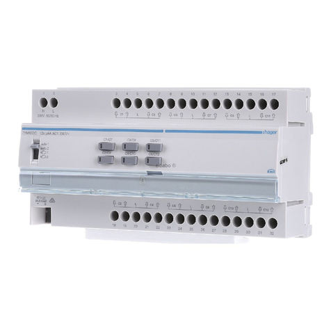
hager TYM632C User manual

hager

hager TYM632C User manual

hager WK305 User manual

hager

hager WK305 User manual

hager H3 x250 User manual

hager

hager H3 x250 User manual

hager tebis TXA204A User manual

hager

hager tebis TXA204A User manual

hager Klik LCM User manual

hager

hager Klik LCM User manual

hager RE 410 Series User manual

hager

hager RE 410 Series User manual

hager RTN100X User manual

hager

hager RTN100X User manual

hager RCBO-AFDD User manual

hager

hager RCBO-AFDD User manual

hager TN002S User manual

hager

hager TN002S User manual

hager RE 310 Series User manual

hager

hager RE 310 Series User manual

hager JK11254D Manual

hager

hager JK11254D Manual

hager RTN300X User manual

hager

hager RTN300X User manual

hager TN002 User manual

hager

hager TN002 User manual

hager ZZ45WAN2PP User manual

hager

hager ZZ45WAN2PP User manual

hager NH00 User manual

hager

hager NH00 User manual

hager TYA606 Series User manual

hager

hager TYA606 Series User manual

hager TRB221A-5A User manual

hager

hager TRB221A-5A User manual

hager TYA610A User manual

hager

hager TYA610A User manual

hager RTN710X User manual

hager

hager RTN710X User manual

hager h3 h400 User manual

hager

hager h3 h400 User manual

hager Vega D FD Series User manual

hager

hager Vega D FD Series User manual

hager TYB601A User manual

hager

hager TYB601A User manual

hager TYB621C User manual

hager

hager TYB621C User manual

hager TYA606A User manual

hager

hager TYA606A User manual

Popular Control Unit manuals by other brands

ZURN QHCMKIT5 installation instructions

ZURN

ZURN QHCMKIT5 installation instructions

ProFlo PF4001PTD installation instructions

ProFlo

ProFlo PF4001PTD installation instructions

Festo VZQA-C-M22C Series Repair instructions

Festo

Festo VZQA-C-M22C Series Repair instructions

FAAC 844 T manual

FAAC

FAAC 844 T manual

National Instruments NI FlexRIO PXIe-7971R Getting started guide

National Instruments

National Instruments NI FlexRIO PXIe-7971R Getting started guide

Mesto Neles ValvGuard VG9000H operating instructions

Mesto

Mesto Neles ValvGuard VG9000H operating instructions

JS Automation MPC3024A user manual

JS Automation

JS Automation MPC3024A user manual

ICStation ZK-301B manual

ICStation

ICStation ZK-301B manual

Velleman K8006 Illustrated assembly manual

Velleman

Velleman K8006 Illustrated assembly manual

Midea SMK-D140HHN1-3 manual

Midea

Midea SMK-D140HHN1-3 manual

Knick Protos Compa 3400(X)-081 user manual

Knick

Knick Protos Compa 3400(X)-081 user manual

Dyna-Flo 570 Operation, Parts, and Instruction Manual

Dyna-Flo

Dyna-Flo 570 Operation, Parts, and Instruction Manual

Pickering PXI BRIC 40-595A user manual

Pickering

Pickering PXI BRIC 40-595A user manual

Edwards PV16EKA instruction manual

Edwards

Edwards PV16EKA instruction manual

Vector OPA2-MOD manual

Vector

Vector OPA2-MOD manual

NPM AD1231 user manual

NPM

NPM AD1231 user manual

Emerson ES-805 Series instruction manual

Emerson

Emerson ES-805 Series instruction manual

Quectel NB-IoT Module Series Hardware design

Quectel

Quectel NB-IoT Module Series Hardware design

manuals.online logo
manuals.online logoBrands
  • About & Mission
  • Contact us
  • Privacy Policy
  • Terms and Conditions

Copyright 2025 Manuals.Online. All Rights Reserved.