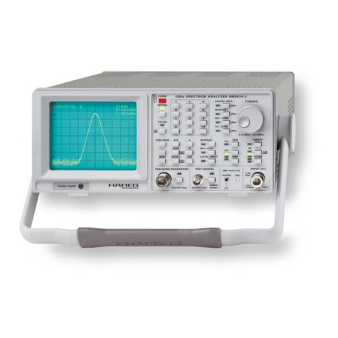
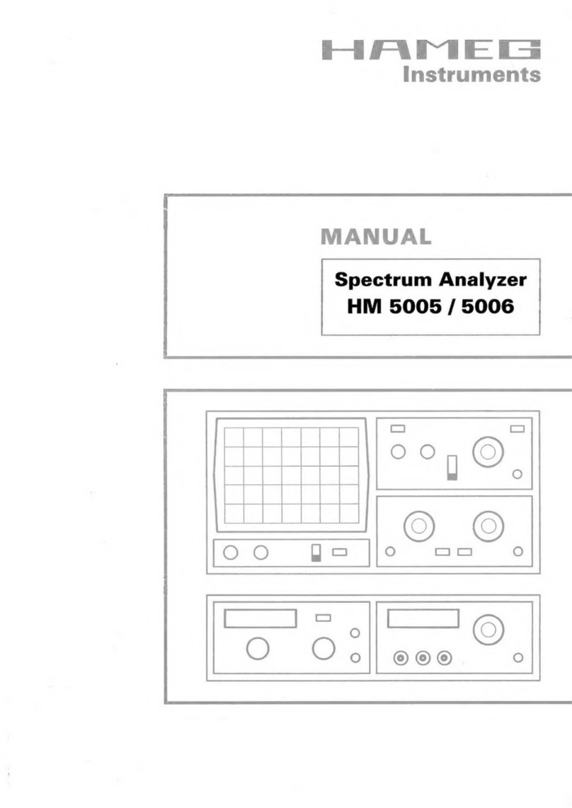
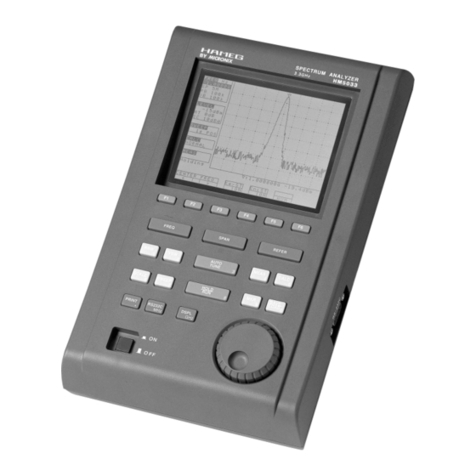
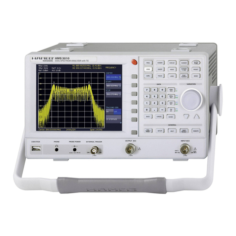
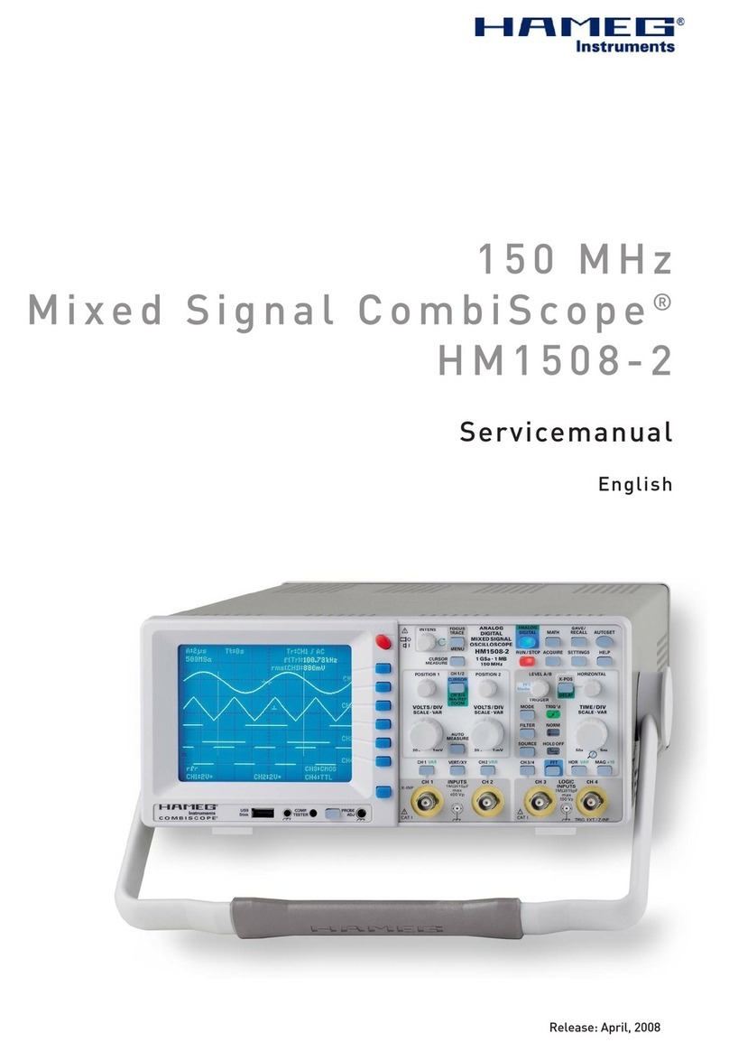
Hameg HM5012-2 User manual

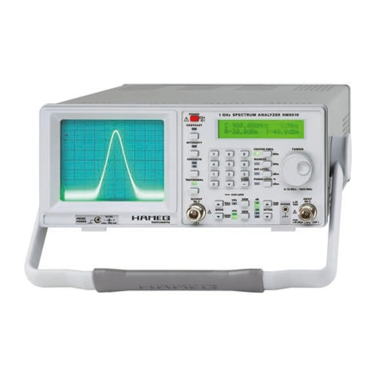
Spectrum-Analyzer
HM5012-2/HM5014-2
Service-Manual

2Subject to change without notice
Hersteller HAMEG Instruments GmbH KONFORMITÄTSERKLÄRUNG
Manufacturer Industriestraße 6 DECLARATION OF CONFORMITY
Fabricant D-63533 Mainhausen DECLARATION DE CONFORMITE
Messkategorie / Measuring category / Catégorie de mesure: I
Verschmutzungsgrad / Degree of pollution / Degré de pollution: 2
Elektromagnetische Verträglichkeit / Electromagnetic compatibility /
Compatibilité électromagnétique
EN 61326-1/A1 Störaussendung / Radiation / Emission:
Tabelle / table / tableau 4; Klasse / Class / Classe B.
Störfestigkeit / Immunity / Imunitee:Tabelle / table / tableau A1.
EN 61000-3-2/A14 Oberschwingungsströme / Harmonic current emissions /
Émissions de courant harmonique:
Klasse / Class / Classe D.
EN 61000-3-3 Spannungsschwankungen u. Flicker / Voltage fluctuations and flicker /
Fluctuations de tension et du flicker.
Datum /Date /Date
15. 07. 2004
Unterschrift / Signature /Signatur
Manuel Roth
Manager
Die HAMEG Instruments GmbH bescheinigt die Konformität für das Produkt
The HAMEG Instruments GmbH herewith declares conformity of the product
HAMEG Instruments GmbH déclare la conformite du produit
Bezeichnung / Product name / Designation:
Spektrumanalysator
Spectrum Analyzer
Analyseur de spectre
Typ / Type / Type: HM5012-2 / HM5014-2
mit / with / avec: –
Optionen / Options / Options: –
mit den folgenden Bestimmungen / with applicable regulations /
avec les directives suivantes
EMV Richtlinie 89/336/EWG ergänzt durch 91/263/EWG, 92/31/EWG
EMC Directive 89/336/EEC amended by 91/263/EWG, 92/31/EEC
Directive EMC 89/336/CEE amendée par 91/263/EWG, 92/31/CEE
Niederspannungsrichtlinie 73/23/EWG ergänzt durch 93/68/EWG
Low-Voltage Equipment Directive 73/23/EEC amended by 93/68/EEC
Directive des equipements basse tension 73/23/CEE amendée par 93/68/CEE
Angewendete harmonisierte Normen / Harmonized standards applied / Normes
harmonisées utilisées
Sicherheit / Safety / Sécurité
EN 61010-1:2001 (IEC 61010-1:2001)
General information concerning the CE marking
HAMEG instruments fulfill the regulations of the EMC directive. The
conformity test made by HAMEG is based on the actual generic- and
product standards. In cases where different limit values are applicable,
HAMEG applies the severer standard. For emission the limits for
residential, commercial and light industry are applied. Regarding the
immunity (susceptibility) the limits for industrial environment have
been used.
The measuring- and data lines of the instrument have much influence
on emmission and immunity and therefore on meeting the acceptance
limits. For different applications the lines and/or cables used may
be different. For measurement operation the following hints and
conditions regarding emission and immunity should be observed:
1. Data cables
For the connection between instruments resp. their interfaces and
external devices, (computer, printer etc.) sufficiently screened cables
must be used. Without a special instruction in the manual for a reduced
cable length, the maximum cable length of a dataline must be less than
3 meters and not be used outside buildings. If an interface has several
connectors only one connector must have a connection to a cable.
Basically interconnections must have a double screening. For IEEE-bus
purposes the double screened cables HZ72S and HZ72L from HAMEG
are suitable.
2. Signal cables
Basically test leads for signal interconnection between test point and
instrument should be as short as possible. Without instruction in the
manual for a shorter length, signal lines must be less than 3 meters
and not be used outside buildings.
Signal lines must screened (coaxial cable - RG58/U). A proper ground
connection is required. In combination with signal generators double
screened cables (RG223/U, RG214/U) must be used.
3. Influence on measuring instruments.
Under the presence of strong high frequency electric or magnetic fields,
even with careful setup of the measuring equipment an influence of
such signals is unavoidable.
This will not cause damage or put the instrument out of operation. Small
deviations of the measuring value (reading) exceeding the instruments
specifications may result from such conditions in individual cases.
4. RF immunity of oscilloscopes.
4.1 Electromagnetic RF field
The influence of electric and magnetic RF fields may become visible
(e.g. RF superimposed), if the field intensity is high. In most cases
the coupling into the oscilloscope takes place via the device under
test, mains/line supply, test leads, control cables and/or radiation.
The device under test as well as the oscilloscope may be effected by
such fields.
Although the interior of the oscilloscope is screened by the cabinet,
direct radiation can occur via the CRT gap. As the bandwidth of
each amplifier stage is higher than the total –3dB bandwidth of the
oscilloscope, the influence RF fields of even higher frequencies may
be noticeable.
4.2 Electrical fast transients / electrostatic discharge
Electrical fast transient signals (burst) may be coupled into the
oscilloscope directly via the mains/line supply, or indirectly via test
leads and/or control cables. Due to the high trigger and input sensitivity
of the oscilloscopes, such normally high signals may effect the trigger
unit and/or may become visible on the CRT, which is unavoidable.
These effects can also be caused by direct or indirect electrostatic
discharge.
HAMEG Ibstruments GmbH
3
Subject to change without notice
Declaration of Conformity 2
General information regarding the CE-marking 2
Spektrum Analyzer HM5012-2 / HM5014-2 4
Specifications 5
Circuit and layout diagrams 8
Content

4Subject to change without notice
HM5012-2 / HM5014-2
Frequency range: 150 kHz to 1 GHz
Amplitude measurement range: – 100 dBm to + 10 dBm
Phase Synchronous, Direct Digital frequency Synthesis (DDS)
Resolution bandwidths (RBW): 9 kHz, 120 kHz and 1 MHz
Pre-compliance EMI measurement
Serial interface for documentation and control
Software for documentation included
Additional measurement functions for EMI measurements
with optional software
HM5014-2 only:
Tracking Generator with output amplitude from – 50 dBm to
+ 1 dBm
Measurement of line-con-
ducted interference
Amplitude-modulated
RF Signal
Amplifier frequency res-
ponse measured using a tra-
cking generator
1 GHz Spectrum Analyzer
HM5014-2

5
Subject to change without notice
Specifications
Inputs / Outputs
Measuring Input: N socket
Input Impedance: 50 Ω
VSWR: (Attn. ≥10 dB) typ. 1.5:1
Tracking Generator Output: N-socket
Output Impedance: 50 Ω
Test Signal Output: BNC socket
Frequency, Level: 48 MHz, -30 dBm (± 2dB)
Supply Voltage for Probes (HZ 530): 6VDC
Audio Output (phone): 3.5 mm Ø jack
RS-232 Interface: 9-pin / Sub-D
Functions
Keyboard Input: Center Frequency, Reference Level,
Tracking Generator Level (HM5014-2 only)
Rotary Encoder Input: Center Frequency, Reference Level, Marker,
Tracking Generator Level (HM5014-2 only)
Max. Hold Detection: Peak Value Acquisition
Quasi-Peak Detection:* Quasi-Peak Valuation
Average: Mean Value Acquisition
Ref. Spectrum Memory: 2kx8bit
SAVE / RECALL: Save and Recall of 10 Instrument Settings
AM demodulation for audio
LOCAL: RS-232 Remote Control OFF
Readout: Display of various Measurement
Parameters
Tracking Generator (HM5014-2 only)
Frequency Range: 0.15 MHz to 1.050 GHz
Output Level: –50 dBm to +1 dBm
Frequency Response (0.15 MHz – 1 GHz)
+1 dBm to -10 dBm: ± 3 dB
-10.2 dBm to -50 dBm: ± 4 dB
Digitization Error: ± 1 digit (0.4 dB)
Spurious Outputs: better than 20 dBc
General information
CRT: D14-363GY, 8 x 10 cm with internal graticule
Acceleration Voltage: approx. 2 kV
Trace Rotation: adjustable on front panel
Ambient Temperature: 10° C to 40° C
Power Supply: 105-253 V, 50 / 60 Hz ± 10 %, CAT II
Power Consumption: approx. 35 W at 230 V/50 Hz
Safety Class: Safety Class I (EN61010-1)
Dimensions (W x H x D): 285 x 125 x 380 mm
Weight (HM5012-2):: approx. 6 kg
Weight (HM5014-2):: approx. 6.5 kg
*) in combination with software AS100E only
Accessories supplied: Line Cord, Operators Manual and Software for Windows
on CD-ROM
Optional accessories: Opto Interface HZ70, Antenna HZ520, Near Field Probe Set
for EMI Diagnosis HZ530
1 GHz Spectrum Analyzer HM5012-2 / HM5014-2
Valid at 23 °C after a 30 minute warm-up period
Frequency Characteristics
Frequency Range: 0.15 MHz to 1.050 GHz
Stability: ± 5 ppm
Ageing: ±1ppm/year
Frequency Resolution: 1 kHz (6 digit in readout)
Center Frequency Range: 0 to 1.050 GHz
LO Frequency Generation: TCXO with DDS (Digital Frequency Synthesis)
Span Setting Range: Zero Span and 1 MHz - 1000 MHz
(1-2-5 Sequence)
Marker:
Frequency Resolution: 1 kHz, 6 digit,
Amplitude Resolution: 0.4 dB, 3 digit
Resolution Bandwidths
(RBW) @6dB: 1 MHz, 120 kHz and 9 kHz
Video Bandwidth (VBW): 4 kHz
Sweep Time
(automatic selection): 40 ms, 320 ms,1 s*)
Amplitude Characteristics (Marker Related) 150 kHz – 1 GHz
Measurement Range: -100 dBm to +10 dBm
Scaling: 10 dB/div., 5 dB/div.
Display Range: 80 dB (10 dB/div.),
40 dB (5 dB/div.)
Amplitude Frequency Response (at 10 dB Attn., Zero Span and RBW
1 MHz, Signal – 20 dBm): ±3dB
Display (CRT): 8 x10 division
Amplitude Scale: logarithmic
Display units: dBm
Input Attenuator Range: 0 - 40 dB (10 dB increments)
Input Attenuator Accuracy
rel. to 10 dB: ±2dB
Max. Input Level (continuous)
40 dB attenuation: +20 dBm (0.1 W)
0 dB attenuation: +10 dBm
Max. DC Voltage: ±25V
Max. Reference Level: +10 dBm
Reference Level Accuracy rel. to 500 MHz, 10 dB Attn., Zero Span and
RBW 1 MHz: ±1dB
Min. Average Noise Level: approx. -100 dBm (RBW 9 kHz)
Intermodulation Ratio
(3rd Order): typical › 75 dBc (2 Signals: 200 MHz,
203 MHz, – 3 dB below Reference Level)
Harmonic Distortion Ratio
(2nd harm.): typical › 75 dBc
(200 MHz, Reference Level)
Bandwidth Dependent Amplitude Error rel. to RBW 1 MHz and Zero
Span: ±1dB
Digitization Error: ± 1 digit (0.4 dB) at 10 dB/div. scaling
(Average, Zero Span)
12
12
12
HM5014-2E/310505/ce · Subject to alterations · © HAMEG Instruments GmbH · ® Registered Trademark · DQS-certified in accordance with DIN EN ISO 9001:2000, Reg.-No.: DE-071040 QM
HAMEG Instruments GmbH · Industriestr. 6 · D-63533 Mainhausen · Tel +49 (0) 6182 800 0 · Fax +49 (0) 6182 800 100 · www.hameg.com · info@hameg.com
A Rohde & Schwarz Company
www.hameg.com

6Subject to change without notice
Block Diagram

7
Subject to change without notice
Interconnection

8Subject to change without notice
Attenuator Driver (ATD)

9
Subject to change without notice
Attenuator Driver (ATD)

10 Subject to change without notice
Tuner Attenuator (RAT)

11
Subject to change without notice
Tuner Attenuator (RAT)

12 Subject to change without notice
Tuner 1. Mixer (RFA)

13
Subject to change without notice
Tuner 1. Mixer (RFA)

14 Subject to change without notice
Tuner 1. Mixer (RFA)

15
Subject to change without notice
Tuner 1. Mixer (RFA)

16 Subject to change without notice
Tuner 1. Mixer (RFA)

17
Subject to change without notice
Tuner 1. Mixer (RFA)

18 Subject to change without notice
RFA-Connector-Board (CRA)

19
Subject to change without notice
RFA-Connector-Board (CRA)

20 Subject to change without notice
Tuner 2. Mixer (RFB)
Other manuals for HM5012-2
1
This manual suits for next models
1
Table of contents
Other Hameg Measuring Instrument manuals
Popular Measuring Instrument manuals by other brands

KERN
KERN ORA 20 BA operating instructions

Agilent Technologies
Agilent Technologies 8504B user guide

PCB Piezotronics
PCB Piezotronics IMI SENSORS ICP 626B03 Installation and operating manual

Veris Industries
Veris Industries E31E84 installation guide

Kathrein
Kathrein MSK 15 Mode d'emploi

Bacharach
Bacharach 3015-4286 Installation & operating instructions