Hameg HZ541 User manual

MANUAL · HANDBUCH · MANUEL
DEUTSCH · ENGLISH
VSWR Messbrücke
VSWR Measuring Bridge
HZ 541

2Änderungen vorbehalten

Änderungen vorbehalten 3
Inhaltsverzeichnis
CE-Erklärung ........................................... 4
Technische Daten ................................... 5
Allgemeines ............................................ 6
Messaufbau ............................................ 7
VSWR-Messbrücke
am Spektrum-Analyser HM 5014-2 .......... 8
Bestimmung des Stehwellen-
verhältnisses und des Reflexionsfaktors .. 9
Formeln .................................................. 10
Lieferumfang und Zubehör ...................... 10
Deutsch .............................................. 5
English ............................................... 12
VSWR Messbrücke
HZ 541

4Änderungen vorbehalten
KONFORMITÄTSERKLÄRUNG
DECLARATION OF CONFORMITY
DECLARATION DE CONFORMITE
Name und Adresse des Herstellers HAMEG GmbH
Manufacturer´s name and address Industriestraße 6
Nom et adresse du fabricant D-63533 Mainhausen
Die HAMEG GmbH bescheinigt die Konformität für das Produkt
The HAMEG GmbH herewith declares conformity of the product
HAMEG GmbH déclare la conformite du produit
Bezeichnung / Product name / Designation: VSWR Messbrücke
VSWR Measuring Bridge
Typ / Type / Type: HZ 541
mit / with / avec: –
Optionen / Options / Options: –
mit den folgenden Bestimmungen / with applicable regulations / avec les directives suivantes
EMV Richtlinie 89/336/EWG ergänzt durch 91/263/EWG, 92/31/EWG
EMC Directive 89/336/EEC amended by 91/263/EWG, 92/31/EEC
Directive EMC 89/336/CEE amendée par 91/263/EWG, 92/31/CEE
Angewendete harmonisierte Normen / Harmonized standards applied / Normes harmonisées utilisées
Elektromagnetische Verträglichkeit / Electromagnetic compatibility / Compatibilité électromagnétique
EN 61326-1/A1
Störaussendung / Radiation / Emission:Tabelle / table / tableau 4; Klasse / Class / Classe B.
Störfestigkeit / Immunity / Imunitee:Tabelle / table / tableau A1.
Datum /Date /Date Unterschrift / Signature /Signatur
12. Jan. 2004
G. Hübenett
Product Manager

Änderungen vorbehalten 5
Elektrische Daten
Frequenzbereich: 150 kHz - 1050 MHz
Wellenwiderstand: 50 Ohm
Richtverhältnis
150 kHz - 300 kHz: >28 dB
300 kHz - 1050 MHz: >35 dB
Reflexionsdämpfung am Messtor
DUT: >20 dB
Einfügungsdämpfung
IN ¡OUT: 20 dB
(150 kHz - 300 kHz)
IN ¡OUT: 17 dB
(300 KHz - 1 GHz)
IN ¡DUT: 1,7 dB
DUT ¡OUT: 16 dB
Belastbarkeit: +26 dBm (400 mW)
Mechanische Daten
Messbrücke:
Abmessungen: 151,5 x 38 x 29,5 mm
(B x T x H) (ohne Anschlüsse)
Gewicht: 450 g
Temperaturbereich: +10° C bis +45 °C
Anschlüsse: N-Buchsen
Tragekoffer:
Abmessungen: 265 x 225 x 50 mm
(B x T x H)
Gesamtgewicht: 950g
(Brücke + Koffer + Zubehör)
Mitgeliefertes Zubehör:
Abschlusswiderstand: 50 Ohm,
VSWR <1 : 1,05 (1 Stück), N-Stecker
Adapter: N-Stecker zu N-Stecker (2 Stück)
Technische Daten HZ 541 VSWR-Messbrücke 50 Ohm

6Änderungen vorbehalten
Sofort nach dem Auspacken sollte die Mess-
brücke auf mechanische Beschädigungen
und lose Teile im Innern überprüft werden.
Falls ein Transportschaden vorliegt, ist sofort
der Lieferant zu informieren. Die Mess-
brücke darf dann nicht in Betrieb gesetzt
werden.
Symbole
Bedienungsanleitung beachten
Sicherheit
Unsere Messbrücken haben das Werk in
sicherheitstechnisch einwandfreiem Zu-
stand verlassen. Sie entsprechen damit auch
den Bestimmungen der europäischen Norm
EN 61010-1 bzw. der internationalen Norm
IEC 61010-1. Um diesen Zustand zu erhalten
und einen gefahrlosen Betrieb sicherzustel-
len, muß der Anwender die Hinweise und
Warnvermerke beachten, die in dieser
Bedienungsanleitung, im Testplan und in
der Service-Anleitung enthalten sind.
Wenn anzunehmen ist dass ein gefahrloser
Betrieb nicht mehr möglich ist, so ist die
Messbrücke
außer Betrieb zu setzen und
gegen unabsichtlichen Betrieb zu sichern.
Diese Annahme ist berechtigt,
Iwenn die Messbrücke sichtbare Beschä-
digungen hat,
Iwenn die Messbrücke lose Teile enthält,
Iwenn die Messbrücke nicht mehr arbei-
tet,
Inach längerer Lagerung unter ungünsti-
gen Verhältnissen (z.B. im Freien oder in
feuchten Räumen),
Inach schweren Transportbeanspruchun-
gen (z.B. mit einer Verpackung, die nicht
den Mindestbedingungen von Post, Bahn
oder Spedition entsprach).
Betriebsbedingungen
Die zulässigeUmgebungstemperaturwährend
des Betriebs reicht von +10 °C... +40 °C. Wäh-
rend der Lagerung oder des Transports darf die
Temperaturzwischen–40 °Cund+70 °Cbetra-
gen. Hat sich während des Transports oder der
Lagerung Kondenswasser gebildet, müssen
die Messbrücke ca. 2 Stunden akklimatisiert
werden, bevor sie in Betrieb genommen wer-
den. Die Messbrücke ist zum Gebrauch in
sauberen, trockenen Räumen bestimmt. Die
Betriebslage ist beliebig.
Garantie
Jede Messbrücke durchläuft vor dem Ver-
lassen der Produktion einen Qualitätstest.
Dennoch ist es möglich, dass ein Bauteil
erst nach längerer Betriebsdauer ausfällt.
Daher wird auf alle Messbrücken eine
Funktionsgarantie von 2 Jahren gewährt.
Voraussetzung ist, dass im Gerät keine Ver-
änderungen vorgenommen wurden. Für Ver-
sendungen per Post, Bahn oder Spedition
wird empfohlen, die Originalverpackung zu
verwenden. Transport- oder sonstige Schä-
den, verursacht durch grobe Fahrlässigkeit,
werden von der Garantie nicht erfasst.
Bei einer Beanstandung sollte man am Ge-
häuse der Messbrücke eine stichwortartige
Fehlerbeschreibung anbringen. Wenn dabei
gleich der Name und die Telefon-Nr. (Vorwahl
undRuf-bzw.Durchwahl-Nr.oderAbteilungs-
bezeichnung) für evtl. Rückfragen angege-
ben wird, dient dies einer beschleunigten
Abwicklung.
Allgemeines

Änderungen vorbehalten 7
Die VSWR Messbrücke HZ 541 besitzt drei
N-Anschlussbuchsen.
IN-Anschluss (Eingang der Messbrücke)
An diesem Anschluss wird die Signalquelle
angeschlossen. Die Signalquelle kann dabei
ein HF-Generator oder der Tracking-Genera-
tor eines Spektrum-Analysators oder Netz-
werk-Analysators sein.
OUT-Anschluss
(Ausgang der Messbrücke)
An diesem Ausgang steht eine Spannung
zur Verfügung, deren Betrag und Phase pro-
portional zum Reflexionsfaktor des Prüf-
objekts ist und mit einem geeigneten
Detektor erfasst werden kann. Ein solcher
Detektor kann ein HF-Wattmeter, ein Mess-
empfänger, der Input eines Spektrum-Ana-
lysators oder Netzwerk-Analysators sein.
!
Instruments
HZ 541 VSWR Bridge 50
150 kHz – 1050 MHz
max.:
+25dBm
30V DC
1,7dB
Loss
OUT
DUT
IN
17 d B
Signalquelle Detektor
Prüfobjekt DUT
(Device Under Test)
DUT-Anschluss (Prüfobjekt)
Das Prüfobjekt sollte möglichst direkt mit
diesem Anschluss verbunden werden. Alle
Adapter oder Kabel zwischen diesem An-
schluss und dem Prüfling verfälschen das
Messergebnis durch zusätzliche Reflexio-
nen.
Um die Verbindungen zwischen der VSWR-
Messbrücke HZ 541 und dem HAMEG Spek-
trum-Analysator (z.B.: HM 5014-2) so kurz
wie möglich zuhalten, ist die Messbrücke so
konstruiert, dass sie direkt über N zu N
Adapter angeschlossen werden kann. Die
Adapter gehören zum Lieferumfang der
Messbrücke.
Messaufbau

8Änderungen vorbehalten
VSWR-Messbrücke am Spectrum-Analysator HM 5014-2
IN-Anschluss mit Tracking-Generator (HM
5014-2)verbunden (Signalquelle)
OUT-Anschluss (HZ 541) mit Analysator-
Eingang (HM 5014-2) verbunden.
Benutzt man einen Spektrum-Analysator
eines anderen Herstellers muss man an
statt der Adapter ein N-Kabel (optoinal) zur
Verbindung benutzen. Siehe Zubehörliste.

Änderungen vorbehalten 9
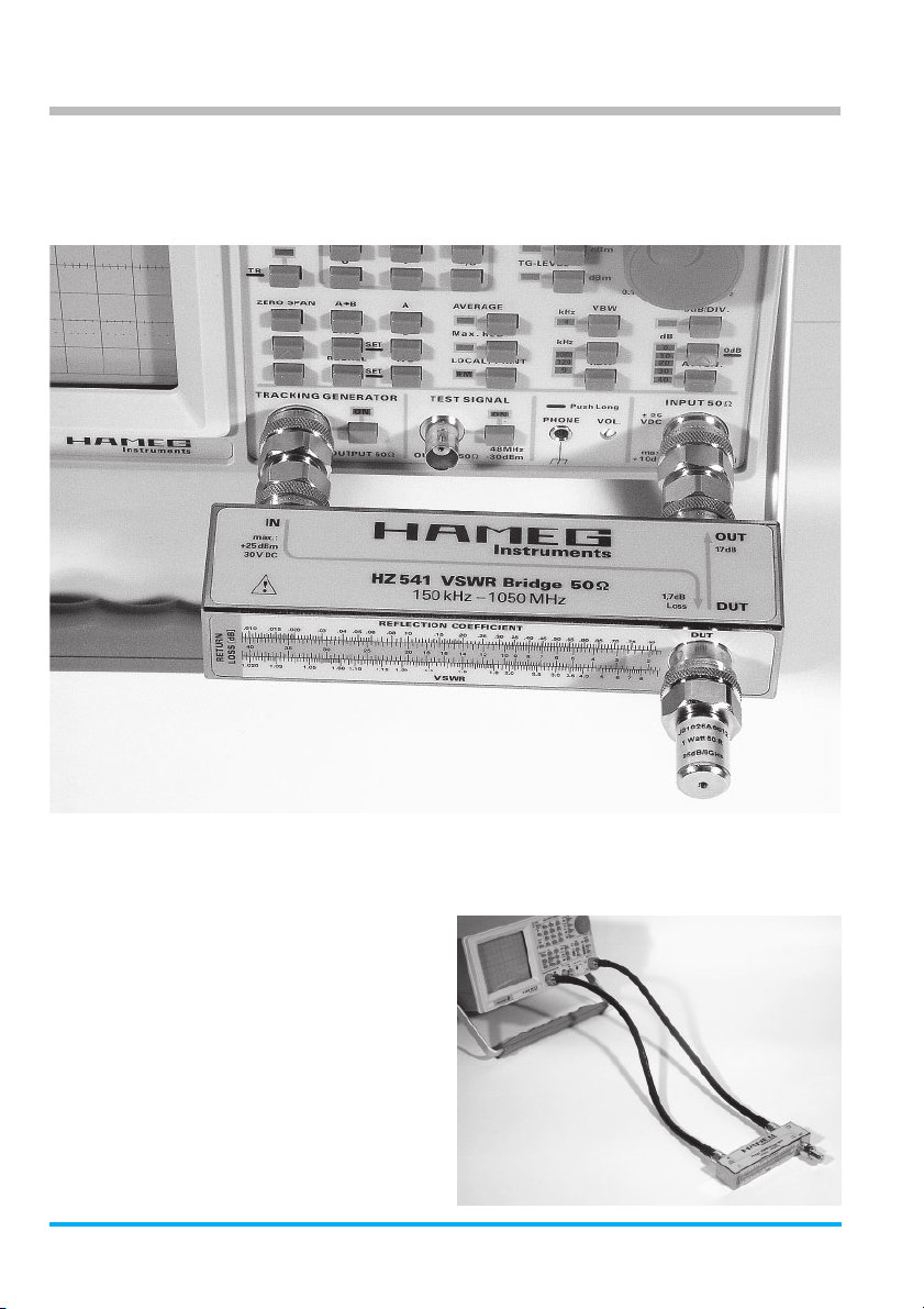
Die VSWR Messbrücke HZ 541 dient zur
Bestimmung des Stehwellenverhältnisses
(VSWR = Voltage Standing Wave Ratio) und
des Reflexionsfaktors (REFLECTION
COEFFICIENT) von Messobjekten, die eine
Impedanz von 50 Ohm haben. Typische
Messobjekte sind Dämpfungsglieder, Ab-
schlusswiderstände, Frequenzweichen, Ver-
stärker, Kabel oder Mischer mit einer Impe-
danz von ebenfalls 50 Ohm. Der Messbereich
ist von 150 kHz bis 1 GHz spezifiziert.
Die gemessene Reflexionsdämpfung (RE-
TURN LOSS) kann z.B. mit Hilfe eines HF-
Signalgenerators und eines Messemp-
fängers auf diskreten Frequenzen ermittelt
werden. Bei der Messung ganzer Frequenz-
bereiche, ist wegen des geringeren Zeit-
aufwands, der Einsatz von Spektrumanaly-
satoren mit eingebauten Trackinggene-
ratoren vorteilhaft.
Die Reflexionsdämpfung ist die Differenz
zwischen einer Messung mit totaler Fehlan-
passung („DUT“-Anschluss offen oder kurz-
geschlossen) und einer Messung mit dem
Messobjekt am „DUT“-Anschluss (DUT =
Device Under TEST).
Der Messwert bei totaler Fehlanpassung
wird wie folgt ermittelt:
1. Die Signalquelle (Tracking – Generator
oder Signalgenerator) wird mit dem „IN“-
Anschluss der Messbrücke verbunden.
2. Der „OUT“- Anschluss der Messbrücke
wird mit dem Eingang des Mess-
empfängers oder Spektrum-Analysators
verbunden.
3. Der „DUT“- Anschluss der Messbrücke
bleibt offen (Leerlauf) was eine totale
Reflexion bewirkt.
Die Höhe des reflektierten Signals wird über
den „OUT“-Anschluss vom Spektrum-Ana-
lysator gemessen und angezeigt. Der Mess-
wert muss registriert bzw. in den Referenz-
speicher abgelegt werden. Funktion: Spei-
chere A nach B (A->B) des Spektrum-Analy-
sators. Dann wird der Analysator auf den A
minus B (A – B) Betrieb umgeschaltet.
Anschließend wird das Prüfobjekt mit dem
„DUT“- Anschluss verbunden. Die Energie,
die zuvor komplett reflektiert wurde, wird
nun durch den Einfluss des Prüfobjekts nicht
mehr im vollen Umfang reflektiert. Es ge-
langt weniger Energie über den „OUT“-
Anschluss an den Spektrum-Analysator. Der
unter diesen Bedingungen angezeigte Diffe-
renzwert in dB ist ein Maß für die Güte des
Prüflings in Bezug auf dessen Anpassung an
den Wellenwiderstand des Systems. Man
bezeichnet diesen Wert als Reflexions-
dämpfung (RETURN LOSS).
Ein idealer 50 Ohm Abschlusswiderstand
reflektiert keinerlei Energie.
Die Reflexionsdämpfung geht dabei gegen
unendlich. In der Praxis lassen sich allerdings
40 dB nur sehr schwer erreichen. Dieser
Wert bedeutet, dass 99% der Energie im
Prüfobjekt „verbraucht“ und nur 1% reflek-
tiert werden.
Aus der in Dezibel gemessenen Reflexions-
dämpfung, lassen sich mit Hilfe der Tabelle
1 der Reflexionsfaktor (REFLECTION
COEFFICIENT)unddas Stehwellenverhältnis
(VSWR) ermitteln. Die Tabelle befindet sich,
zurschnellerenBestimmungderWerte,auch
auf der Messbrücke.
Bestimmung des
Stehwellenverhältnisses und des Reflexionsfaktors

10 Änderungen vorbehalten
VSWR
RETURN
LOSS [dB]
REFLECTION COEFFICIENT
Umrechnungen:
a = Return Loss [dB]
r = Reflexionsfaktor des Messobjekts
s = Stehwellenverhältnis SWR
Zo= Wellenwiderstand des Systems 50Ω
Z = Impedanz des Prüfobjekts
Beispiel:
Return Loss vom
Spektrum-Analysator = 20 dB
VSWR: 1,222
Reflexionskoeffizient: 0,1 (10%)
r = 10 -0,05 · a
1+ IrI
s = ––––––
1 – IrI
1+ r
s = –––––– Zo
1–r
Formeln
Lieferumfang
HZ 541 VSWR-Bridge-Set
bestehend aus:
VSWR-Bridge, 50 Ohm, 1 GHz 1 Stück
Adapter N[male] to N[male] 2 Stück
Abschlusswiderstand 50 ΩN[male] 1 Stück
Transportkoffer 1 Stück
Benutzer-Handbuch 1 Stück
Garantiekarte 1 Stück
Lieferumfang und Zubehör
Zubehör
HZ 523 Adapter N[male] zu N[male] *)
HZ 524 Adapter N[female] zu N[female]
HZ 29 Adapter N[male] zu BNC[female]
HZ 19 Adapter N[male] zu SMA[female]
HZ 525 Abschlusswiderstand 50 ΩN[male] *)
HZ 526 Kabel, 500 mm, N[male] zu N[male]
HZ 527 Kabel, 1000 mm, N[male] zu N[male]
*) im Lieferumfang HZ 541 enthalten

Änderungen vorbehalten 11

12 Subject to change without notice
Contents
CE declaration ........................................ 4
Specifications ........................................ 13
General remarks .................................... 14
Measurement set-up ............................. 15
VSWR bridge connected to the
Spectrum Analyser HM5014-2 .............. 16
How to determine the VSWR and the
Reflection coefficient ............................ 17
Formulae ................................................ 18
Contents of shipment and accessories. 18
Deutsch .............................................. 5
English ............................................... 12
VSWR
Measuring Bridge
HZ 541

Subject to change without notice 13
Electrical specifications
Frequency range: 150 kHz – 1050 MHz
Impedance: 50 ohms
Directional ratio:
150 kHz - 300 kHz: >28 dB
300 kHz - 1050 MHz: >35 dB
Reflection damping at input
DUT: > 20 dB
Insertion loss
IN to OUT: 20 dB
(150 – 300 kHz)
17 dB
(300 kHz – 1 GHz)
IN to DUT: 1.7 dB
DUT to OUT: 16 dB
Maximum power
dissipation: +26 dBm (= 400 mW)
Mechanical specifications
Measurement bridge:
Dimensions
(W x D x H): 151.5 x 38 x 29.5 mm
Weight: 450 g
Temperature range: +10 .. +45 degrees C
Connectors: type N
Case:
Dimensions
(W x D x H): 265 x 255 x 50 mm
Total weight: 950 g
(bridge + case + accessories)
Accessories supplied:
1 ea. resistor 50 ohms, VSWR < 1 : 1.05
1 ea. N connector male
2 ea. adapter N male to N male
Specifications HZ541
VSWR Measurement bridge 50 ohms

14 Subject to change without notice
General remarks
After unpacking check for mechanical
damageandloosepartsfloatingaround inside
the instrument. In case of damage please
inform the transport company immediately.
Do not operate the instrument.
Symbol:
Please consult the manual
Safety instructions
Our measurement bridges did leave the
factory in perfect condition. They conform
hence to the European standards EN 61010-
1 resp. IEC 61010-1. In order to preserve
conformity and ensure safe operation the
user is requested to observe the guidelines
and warning hints in this manual, the test
and service instructions.
Whenever it is suspected that safe operation
may be endangered the bridge should be
taken out of service and protected against
unauthorized operation.
Safe operation may be endangered if any of
the following is the case:
IThe bridge shows visible damage.
ILoose parts floating around inside.
IThe bridge does not function properly.
IAfter prolonged storage under un-
favourable conditions (e.g. in the open or
in damp rooms)
IFollowing excessive transport conditions
(e.g. the transport package did not
correspond to minimum requirements by
mail, rail or other carriers)
Operating conditions
The permissible operating temperature is
+10 ... +40 degr. C. During transport and
storage the temperature may be – 40 ...
+ 70 degr. C. In case of condensation after
transport it is necessary to dry the bridge for
at least 2 hrs. prior to operation. The bridge
is destined for operation in clean, dry rooms.
Warranty
Each bridge has been quality tested before
shipment. In spite of this it is possible that a
component may fail after a substantial
operating period. We warrant the function
for 2 years, provided the instrument has not
been tampered with or was modified. We
recommend to keep the original packing in
case shipment for repair should be neces-
sary. The warranty does not include any
damage due to gross neglect or transport. In
case of shipment for repair please attach a
note to the case indicating the reasons for
repair and your name, address, phone
number and extension number. This will
speed up the processing of your request.

Subject to change without notice 15
!
Instruments
HZ 541 VSWR Bridge 50
150 kHz – 1050 MHz
max.:
+25dBm
30V DC
1,7dB
Loss
OUT
DUT
IN
17 d B
Signal source Detector
Device Under Test
Measurement set-up
The VSWR bridge HZ 541 has 3 N female
N-connectors.
IN = input to the bridge
Here the signal source is to be connected.
This may be a HF-generator, the tracking
generator of a spectrum analyzer or network
analyzer.
OUT = Output of the bridge
At this output a voltage is available the
amplitude and phase of which are proportio-
nal to the reflection coefficient of the DUT
and which may be measured using a suitable
detector. A suitable detector may be a HF-
wattmeter, the input of a spectrum analyzer
or network analyzer.
DUT = Device under test – connection
The DUT should be connected as closely as
possible, any cable or adapter inbetween
will affect the measurement as they cause
additional reflections.
In order to keep the connections short
between the VSWR bridge HZ 541 and the
Hameg Spectrum Analyzer (e.g. HM 5014-
2) the bridge has been designed so that it
canbe connected directly via NtoNadapters.
Two adapters are enclosed with the
instrument.

16 Subject to change without notice
VSWR-Bridge
connected to Spectrum-Analyzer HM 5014-2
ConnecttheIN input to the tracking generator
of the HM 5014-2 (signal source)
Connect the OUT terminal of the HZ 541 to
the input of the analyzer HM 5014-2.
In case a spectrum analyzer of another
manufacturer is used the adapters have to
replaced by N cables (optional).
Please refer to list of accessories.

Subject to change without notice 17
How to determine the
VSWR and the reflection coefficient
The VSWR bridge HZ 541 allows the
measurement of the voltage standing wave
ratio (VSWR) and the reflection coefficient
of 50 ohm devices. Typical objects are e.g.
50 ohm attenuators, load resistors, am-
plifiers, cables, mixers, frequency selective
devices. The frequency range is 150 kHz to
1 GHz.
The return loss measurement requires a
HF-signal generator and a HF-receiver and
is possible for discrete frequencies. If it is
necessary to extend the measurement over
greater frequency ranges it will be advan-
tageous and time saving to select a spectrum
analyzer with a tracking generator instead.
The return loss is determined by the diffe-
rence of the results of two measurements:
first measurement with the DUT terminal
open or short-circuited, i.e. total mismatch,
second measurement with the device under
test connected to the DUT terminal.
The measurement result from a total
mismatch is achieved thus:
1.Connectthesignalsource(signal generator
or tracking generator) to the N connector
IN.
2. Connect the OUT terminal of the bridge to
the input of the receiver or spectrum
analyzer.
3.Leave the DUT terminal openwhichequals
total mismatch.
The spectrum analyzer will indicate the
amplitude of the reflected signal from OUT.
This result must be registered or stored in
the reference memory. Function: „Store A
to B (A>B)“ of the spectrum analyzer. Then
switchthespectrumanalyzertothe operating
mode „A minus B (A – B)“.
Continue by connecting the device under
test to the DUT terminal. Now the reflected
energy(100 % in the previousmeasurement)
will depend upon the properties of the DUT,
in general the reflected energy will be lower
thanbefore, again measured by the spectrum
analyzerwhich will now indicate the algebraic
difference between both measurements in
dB which is the desired return loss.
Of course, an ideal 50 ohm load will not
reflect any energy, the return loss will
become infinite. In reality more than appr. 40
dB are hard to achieve. 40 dB means that
99% of the energy will be absorbed by the
DUT and only 1% will be reflected.
Once the return loss has been determined
use table 1 to read the REFLECTION
COEFFICIENT and the VSWR. This table is
also available on top of the bridge.

18 Subject to change without notice
VSWR
RETURN
LOSS [dB]
REFLECTION COEFFICIENT
Calculations:
a = Return Loss [dB]
r = Reflection coefficient of the DUT
s = VSWR
Zo= System impedance = 50 ohms
Z = Impedance of the DUT
Example:
Return loss as indicated on the spectrum
analyzer = 20 dB
VSWR = 1.222
Reflection coefficient = 0.1 = 10 %.
r = 10 -0,05 · a
1+ IrI
s = ––––––
1 – IrI
1+ r
s = –––––– Zo
1–r
Formulas
Contents of shipment and accessories
Set of HZ541 bridge consisting of:
1 ea. VSWR bridge 50 ohms, 1 GHz
2 ea. Adapters N male to N male (HZ523)
1 ea. 50 ohm load resistor (HZ525)
1 ea. transport case
1 ea. manual
1 ea. warranty document
Acessories:
HZ523 Adapter N male to N male*)
HZ524 Adapter N female to N female
HZ29 Adapter N male to BNC female
HZ19 Adapter N male to SMA female
HZ525 50 ohm load resistor*)
HZ526 Cable, 500 mm, N male to N male
HZ527 Cable, 1000 mm, N male to N male
*) = included in set of HZ 541

Subject to change without notice 19

Printed in Germany
44-Z541-0000
HAMEG GmbH
Industriestraße 6
D-63533 Mainhausen
Telefon: (0 61 82) 800-0
Telefax: (0 61 82) 800-100
E-mail: sales@hameg.de
Oscilloscopes
Multimeters
Counters
Frequency Synthesizers
Generators
R- and LC-Meters
Spectrum Analyzers
Power Supplies
Curve Tracers
Internet:
www.hameg.de
Stand: 19/02/2004-gw
Other manuals for HZ541
1
Table of contents
Languages:
Other Hameg Measuring Instrument manuals